
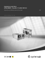
Sabroe enclosure
for ChillPAC, HeatPAC and ChillPAC LP
Installation and operation manual EN


Installation and operation manual
0013321 en 2023.05 3/20
Contents
1. Introduction ..........................................................................................4
2. Transport...............................................................................................5
2.1 Transport ....................................................................................5
2.2 Lifting the enclosure .....................................................................5
2.3 Fixing the enclosure during transport .............................................6
2.4 Enclosed trailer............................................................................6
2.5 Transport security ........................................................................6
3. Installation on site .................................................................................7
3.1 Panel adjustment .........................................................................7
3.2 Lifting brackets ...........................................................................8
3.3 Safety relief system .....................................................................8
3.4 Electrical connection ....................................................................9
3.5 Settings for heating panels ...........................................................9
3.6 Drain connection........................................................................10
4. Service of the plant and enclosure ...................................................... 11
4.1 Safety ....................................................................................... 11
4.2 Area classification...................................................................... 12
4.3 Leak detection system................................................................ 13
4.4 Evacuation fan........................................................................... 13
4.5 Access for service...................................................................... 14
4.6 Sensors ....................................................................................16
4.7 Ventilation ................................................................................. 17
4.8 Oil trap for protection of safety valves .......................................... 17
4.9 Siren and alarm .........................................................................18
4.10 Access for major repairs or service.............................................. 18
5. Appendices ......................................................................................... 20

Installation and operation manual
4/20 0013321 en 2023.05
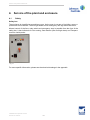
Introduction
1. Introduction
This manual contains guidelines for transport, installation and service of the Sabroe enclosure
and instructions on how to ensure access to the equipment inside the enclosure.

Installation and operation manual
0013321 en 2023.05 5/20
Transport
2. Transport
2.1 Transport
The enclosure is top heavy. See the centre of gravity location on the specific GA drawings.
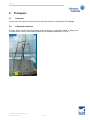
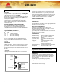
2.2 Lifting the enclosure
A crane, which can lift the stated weight of the enclosure, is required. Further, a lifting yoke
must be used to make sure the panel plates are not damaged when lifted, see Fig. 1
Fig. 1

Installation and operation manual
6/20 0013321 en 2023.05
Transport
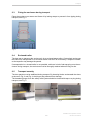
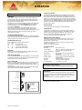
2.3 Fixing the enclosure during transport
Place the enclosure on straws and fasten it by lashing straps to prevent it from tipping during
transport, see Fig. 2.
Fig. 2
2.4 Enclosed trailer
The best way to transport the enclosure is in an enclosed mega trailer. Customised enclosures
that cannot be transported in an enclosed trailer must NOT be covered by a tarpaulin instead,
as the tarpaulin may damage the panels.
If transportation in a closed trailer is not possible, and there is risk of salt spraying onto the en-
closure during transport, the enclosure must be thoroughly washed when arriving on site.
2.5 Transport security
The door panels must be stabilised during transport. By inserting blocks underneath the doors
as shown in Fig. 3 and Fig. 4, the hinges are protected from damage.
The threaded plunger from the safety relief system should be closed with tape or a plug during
transport, see Fig. 5
Fig. 3 Fig. 4 Fig. 5
Truck

Installation and operation manual
0013321 en 2023.05 7/20
Installation on site
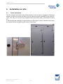
3. Installation on site
3.1 Panel adjustment
The door hinges may loosen a little during transport so that the door is sagging or crooked on
delivery, and this may cause the door to hit the aluminum profile (indicated by the green ar-
rows). This may occur even though transport bricks have been used as instructed in section
2.5.
It may therefore be necessary to adjust the door in the hinge to make it open and close prop-
erly. Adjust the door by tightening the screws in the hinges.

Installation and operation manual
8/20 0013321 en 2023.05
Installation on site
3.2 Lifting brackets
When the enclosure is placed on site, the lifting bracket should be disassembled and stored, if
needed. See Fig. 6.
Fig. 6
3.3 Safety relief system
Remove the plug or tape to assemble the rest of the safety relief system with the included pipe
fittings. The opening should point down, see Fig. 7 and Fig. 8.
Fig. 7 Fig. 8

Installation and operation manual
0013321 en 2023.05 9/20
Installation on site
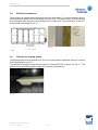
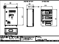
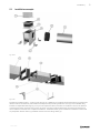
3.4 Electrical connection
The enclosure is supplied with a reinforced panel for cable lead-in. The exact location of the re-
inforced panel is shown in the GA drawing, see also Fig. 9. The panel section is reinforced with
a glued double outer plate to mount cable glands for cable entry. The construction of the rein-
forced panel is illustrated in Fig. 10.
Fig. 9
Fig. 10
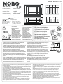
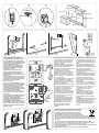
3.5 Settings for heating panels
The heating panel secures against frost. The turn-on temperature should be set at 5°C and the
turn-off temperature at 15°C.
To install the thermostat, follow the instructions in ”Nobø NCU-2Te” manual, see Fig. 11. The
data sheet for the heating panel is attached in section 5. Appendices.
Fig. 11
Reinforced plate
for cable glands
Inside:
Perforated plate
In the middle:
Insulation
Outside:
2 x alu-zink plate

Installation and operation manual
10/20 0013321 en 2023.05
Installation on site
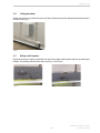
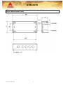
3.6 Drain connection
The enclosure has two drain pipes on the side of the base frame. They serve as drain for the
entire floor of the enclosure. The drain pipes are 50 mm Blücher EuroPipes.
Fig. 12: Drain on the enclosure

Installation and operation manual
0013321 en 2023.05 11/20
Service of the plant and enclosure
4. Service of the plant and enclosure
4.1 Safety
Safety box
The enclosure is classified as a machinery room. As the room is not part of a building, some re-
quirements can be waived. There is light inside and an emergency exit sign above the doors.
Manual control of the fans, main switch and emergency stop is possible from the front of the
safety box. It has indicators for Fan running, Gas detector (low and high alarm) and Tempera-
ture from inside probe.
Fig. 13
For more specific information, please see the electrical drawings in the appendix.

Installation and operation manual
12/20 0013321 en 2023.05
Service of the plant and enclosure
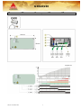
4.2 Area classification
All refrigerant-containing parts are located in a ventilated enclosure or open air. The ventilated
enclosure is classified as a machinery room, and the requirements for a class III location are
applied (EN 378).
As a unit, the enclosure is intended for use in normal areas; however, the inside of the venti-
lated enclosure and a volume around the ventilation outlet opening are zone 2 areas during
normal operation.
Under ATEX, areas are classified according to the hazards associated with flammable gas.
The following classification applies to the inside of the refrigerated and ventilated enclosure:
•Zone 2: an area in which a flammable gas atmosphere is not likely to occur during nor-
mal operation, and if it does occur, it will exist for a short period of time only.
•Secondary grade of release: this is not expected to occur during normal operation,
and if it does occur, it will be infrequent and for short periods of time only.
A refrigerant detector and ventilation are suitable equipment for zone 2: a refrigerant detector
fitted into the enclosed space to start forced ventilation, if necessary, and to isolate all electrical
ignition sources that are not suitable for zone 2 as ultimate protection (EN 60079-10).
The local fire authorities may have certain additional requirements for the location of the plant.
Such requirements may include:
• Distance to buildings and other machinery
• ATEX according to EN 60079-10 and EN 378-3
The unit fully complies with the requirements of both EN 60079-10 and EN 378-3.
Fig. 14
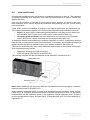
Note: When installing a unit, it must be taken into consideration that the emergency ventilation
exhaust outlet is zone 2 (EN 60079-10).
When installing equipment within 2 metres in all directions from the ventilation outlet, as illus-
trated in Fig. 14, all ignition sources must either be suitable equipment for zone 2 or electrically
isolated when the leak detection system in the enclosure detects high level alarm. This area
must be marked with the signs “No open flame”, “Flammable gas” and “The unit is filled with re-
frigerant R717”.
Safety valve outlet
Ventilation outlet
Zone 2
2 m
2 m
2 m

Installation and operation manual
0013321 en 2023.05 13/20
Service of the plant and enclosure
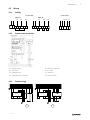
4.3 Leak detection system
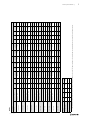
The leak detection system has two levels:
• Level A: High level - Emergency stop
• Level B: Low level - Alarm
Function Normal
operation
Level A
High level
Level B
Low level
Refrigerant detector ON ON ON
Evacuation fan OFF ON ON
Yellow indicator light OFF ON ON
Red indicator light OFF ON OFF
Refrigeration system ON OFF ON
Potential-free signal OFF ON ON
Table 1: Operation condition with refrigerant detector
Level A: Emergency stop: The safety box makes an emergency stop signal, and then voltage
will be disconnected to all electrical equipment in the compressor enclosure and all equipment
in the zone 2 area outside the enclosure. This requires an external power switch, which must
be supplied by the customer. The power switch is not part of the enclosure delivery.
The refrigerant detector and evacuation fan are still in operation as they are ATEX executions
(Equipment Group II category 2).
The red indicator light is ON in the electrical panel.
Start-up after emergency stop: reset the plant manually on the push-button.
Level B: Alarm: The evacuation fan starts, and the refrigeration system continues operating.
4.4 Evacuation fan
When the evacuation fan is in operation, there must be an underpressure in the enclosure. If
the differential pressure switch detects missing underpressure for more than 60 seconds, it will
issue a warning via an indicator light in the electrical panel. The operator must then locate the
reason for the missing underpressure on the enclosure. Check for instance that the machine
doors are closed correctly, and check the direction of rotation of the evacuation fan.
The evacuation fan also starts if the temperature inside the enclosure exceeds the set value.
The refrigeration plant will still run. The evacuation fan can also be started manually on the
changeover switch.

Installation and operation manual
14/20 0013321 en 2023.05
Service of the plant and enclosure
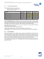
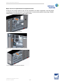
4.5 Access for service
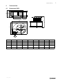
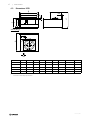
Fig. 15 - Fig. 17 show the access options for a specific “6 high” version enclosure. The number
of sections and the positioning of doors may vary depending on the plant inside. However, in
general, access will be possible as shown in Fig. 15 - Fig. 17 through the doors or demount-
able panels.
A: Panel access
B: Door access D: End door access
Fig. 15
Fig. 16 Fig. 17
D

Installation and operation manual
0013321 en 2023.05 15/20
Service of the plant and enclosure
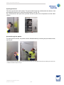
Opening the doors
The doors provide the main access. They are locked in the top, middle and at the bottom. Use
the supplied square key to unlock the three latches, see Fig. 18.
Fig. 19 shows how the open door provides access to part of the compressor and the WHC
system.
Fig. 18 Fig. 19
Access through the panels
For extra service access, the panels can be disassembled by loosening the pan head screws,
see Fig. 20.
Fig. 20: Loosen the pan head screws and remove the panels. Press your hand against the panel when loosening the last screws
to make sure it does not tip over on you.

Installation and operation manual
16/20 0013321 en 2023.05
Service of the plant and enclosure
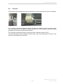
4.6 Sensors
Two sensors are mounted at the top of the enclosure: one for ammonia and one for ventilation.
Fig. 21 Fig. 22
Fig. 21 shows the ammonia detector, which activates the ventilation system at certain quanti-
ties (350 mg/m3starts a prealarm) and gives signal to turn off the power to the plant at other
quantities (21,200 mg/m3starts the main alarm).
Fig. 22 shows a temperature sensor, which starts the ventilation system at 35°C.
It is recommended to test the detector system twice a year. See attachment in section 5. Ap-
pendices for the detector instructions.

Installation and operation manual
0013321 en 2023.05 17/20
Service of the plant and enclosure
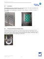
4.7 Ventilation
Check regularly that the ventilation filter is not clogged with dirt. The filter is accessible from
the inside of the door panel, see Fig. 23 and Fig. 24.
The operation and maintenance instruction for the ventilator is attached in section 5.
Appendices.
Fig. 23 Fig. 24
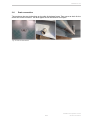
4.8 Oil trap for protection of safety valves
Check regularly that the oil trap has oil. The green ball should float in the sight glass, Fig. 25.
The oil trap prevents moisture from getting into the safety valve and cause jamming. If the oil
trap is empty, check if there has been a pressure relief from the vessels. If necessary, there is
a nipple for charging and one for draining oil, see Fig. 25.
Fig. 25

Installation and operation manual
18/20 0013321 en 2023.05
Service of the plant and enclosure
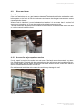
4.9 Siren and alarm
Do NOT open the door, if the siren and alarm are on.
If the siren and alarm are on, gas has been detected. The detection will also activate the venti-
lation system to let fresh air into the enclosure and ensure that the gas concentration cannot
cause explosion hazard.
When a leak is identified, it must be determined whether it is so severe that it requires full
emergency procedures, or if it can be contained by trained personnel on site.
The siren and alarm are placed on the outside of the enclosure over the double door in the end
or over the control box at the front.
Fig. 26
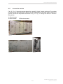
4.10 Access for major repairs or service
If major repair is required, the entire front and most of the back can be demounted. Pay atten-
tion to disassembly of panels with pipe penetration as they will require new insulation and cov-
ering at the pipes. Also be aware of the three-part panel section with the control box, which is
difficult to disassemble because of wires etc.
Do not dismantle both sides at the same time as this may damage the roof.
Fig. 27

Installation and operation manual
0013321 en 2023.05 19/20
Service of the plant and enclosure
Major service or replacement of compressor/motor
If there is not enough space to pull out the crankshaft, the entire compressor must be pulled
out sideways from the enclosure. The compressor or motor can be pulled out by using a forklift,
sliding bench or a lightweight portable gantry crane.
Fig. 28: How to pull or crane out the motor
Fig. 29: How to pull the crankshaft out of the compressor
Fig. 30: How to pull or crane out the compressor

Installation and operation manual
20/20 0013321 en 2023.05
Appendices
5. Appendices
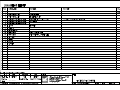
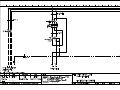
Please find these attachments in the following pages:
1. Electrical drawings for Sabroe enclosure
2. Ventilator manual (Systemair)
3. R717 detector manual (Samon)
4. Heating panel (Nobø)
La page est en cours de chargement...
La page est en cours de chargement...
La page est en cours de chargement...
La page est en cours de chargement...
La page est en cours de chargement...
La page est en cours de chargement...
La page est en cours de chargement...
La page est en cours de chargement...
La page est en cours de chargement...
La page est en cours de chargement...
La page est en cours de chargement...
La page est en cours de chargement...
La page est en cours de chargement...
La page est en cours de chargement...
La page est en cours de chargement...
La page est en cours de chargement...
La page est en cours de chargement...
La page est en cours de chargement...
La page est en cours de chargement...
La page est en cours de chargement...
La page est en cours de chargement...
La page est en cours de chargement...
La page est en cours de chargement...
La page est en cours de chargement...
La page est en cours de chargement...
La page est en cours de chargement...
La page est en cours de chargement...
La page est en cours de chargement...
La page est en cours de chargement...
La page est en cours de chargement...
La page est en cours de chargement...
La page est en cours de chargement...
La page est en cours de chargement...
La page est en cours de chargement...
La page est en cours de chargement...
La page est en cours de chargement...
La page est en cours de chargement...
La page est en cours de chargement...
La page est en cours de chargement...
La page est en cours de chargement...
La page est en cours de chargement...
La page est en cours de chargement...
La page est en cours de chargement...
La page est en cours de chargement...
La page est en cours de chargement...
La page est en cours de chargement...
-
 1
1
-
 2
2
-
 3
3
-
 4
4
-
 5
5
-
 6
6
-
 7
7
-
 8
8
-
 9
9
-
 10
10
-
 11
11
-
 12
12
-
 13
13
-
 14
14
-
 15
15
-
 16
16
-
 17
17
-
 18
18
-
 19
19
-
 20
20
-
 21
21
-
 22
22
-
 23
23
-
 24
24
-
 25
25
-
 26
26
-
 27
27
-
 28
28
-
 29
29
-
 30
30
-
 31
31
-
 32
32
-
 33
33
-
 34
34
-
 35
35
-
 36
36
-
 37
37
-
 38
38
-
 39
39
-
 40
40
-
 41
41
-
 42
42
-
 43
43
-
 44
44
-
 45
45
-
 46
46
-
 47
47
-
 48
48
-
 49
49
-
 50
50
-
 51
51
-
 52
52
-
 53
53
-
 54
54
-
 55
55
-
 56
56
-
 57
57
-
 58
58
-
 59
59
-
 60
60
-
 61
61
-
 62
62
-
 63
63
-
 64
64
-
 65
65
-
 66
66


dans d''autres langues
Autres documents
-
Danfoss OP-LSQM Mode d'emploi
-
Danfoss Optyma™ Plus P02 (A2L) Guide d'installation
-
Danfoss MBS 4050 Guide d'installation
-
Warm Tech WTRIC2000-7 Manuel utilisateur
-
Eaton 16A CEAG IEC 60309 Zone 1 Devices Mode d'emploi
-
Eaton GHG 514 Operating Instructions Manual
-
Eaton GHG 511 Mode d'emploi
-
Eaton Crouse-Hinds Manuel utilisateur
-
-
Fluidwell F040 Le manuel du propriétaire