Porter Cable PCE6430 Manuel utilisateur
- Catégorie
- Outils électroportatifs
- Taper
- Manuel utilisateur
Ce manuel convient également à

LAMINATE TRIMMER
DÉTOUREUSE À STRATIFIÉS
DESBASTADOR LAMINAR
Part No. N285401 NOV13 Copyright © 2013 PORTER-CABLE
www.portercable.com
INSTRUCTIVO DE OPERACIÓN, CENTROS
DE SERVICIO Y PÓLIZA DE GARANTÍA.
LÉASE ESTE INSTRUCTIVO
ANTES DE USAR EL PRODUCTO.
Instruction manual
Manuel d'instructions
Manual de'instrucciones
Français : Page 15
Español: Página 29
PCE6430
PCE6435

2 - ENG
TABLE OF CONTENTS
SAFETY GUIDELINES- DEFINITIONS .....................................................................2
GENERAL POWER TOOL SAFETY WARNINGS ....................................................2
ADDITIONAL SPECIFIC SAFETY RULES ................................................................ 4
COMPONENTS ...................................................................................................... 7
OPERATION ...........................................................................................................6
MAINTENANCE ....................................................................................................12
SERVICE ..............................................................................................................13
ACCESSORIES ....................................................................................................13
WARRANTY .......................................................................................................... 13
FRANÇAIS ............................................................................................................15
ESPAÑOL .............................................................................................................29
SAFETY GUIDELINES - DEFINITIONS
DANGER
indicates an imminently hazardous situation which, if not avoided,
will result in death or serious injury.
WARNING
indicates a potentially hazardous situation which, if not avoided,
could result in death or serious injury.
CAUTION
indicates a potentially haz ard ous situation which, if not avoided,
may result in minor or mod er ate injury.
NOTICE:
used without the safety alert symbol indicates potentially haz-
ardous situation which, if not avoided, may result in property damage.
WARNING
To reduce the risk of injury, read the instruction manual.
GENERAL POWER TOOL SAFETY WARNINGS
Read all safety warnings and all instructions Failure to
follow the warnings and instructions may result in electric
shock, fire and/or serious injury.
SAVE ALL WARNINGS AND INSTRUCTIONS
FOR FUTURE REFERENCE
The term “power tool” in the warnings refers to your mains-operated (corded) power
tool or battery-operated (cordless) power tool.
1) WORK AREA SAFETY
a) Keep work area clean and well lit. Cluttered or dark areas invite accidents.
b) Do not operate power tools in explosive atmospheres, such as in the
presence of flammable liquids, gases or dust. Power tools create sparks
which may ignite the dust or fumes.
c) Keep children and bystanders away while operating a power tool.
Distractions can cause you to lose control.
2) ELECTRICAL SAFETY
a) Power tool plugs must match the outlet. Never modify the plug in any
way. Do not use any adapter plugs with earthed (grounded) power tools.
Unmodified plugs and matching outlets will reduce risk of electric shock.

3 - ENG
b) Avoid body contact with earthed or grounded surfaces such as pipes,
radiators, ranges and refrigerators. There is an increased risk of electric
shock if your body is earthed or grounded.
c) Do not expose power tools to rain or wet conditions. Water entering a
power tool will increase the risk of electric shock.
d) Do not abuse the cord. Never use the cord for carrying, pulling or
unplugging the power tool. Keep cord away from heat, oil, sharp edges
or moving parts. Damaged or entangled cords increase the risk of electric
shock.
e) When operating a power tool outdoors, use an extension cord suitable
for outdoor use. Use of a cord suitable for outdoor use reduces the risk of
electric shock.
f) If operating a power tool in a damp location is unavoidable, use a ground
fault circuit interrupter (GFCI) protected supply. Use of a GFCI reduces the
risk of electric shock.
3) PERSONAL SAFETY
a) Stay alert, watch what you are doing and use common sense when
operating a power tool. Do not use a power tool while you are tired
or under the influence of drugs, alcohol or medication. A moment of
inattention while operating power tools may result in serious personal injury.
b) Use personal protective equipment. Always wear eye protection.
Protective equipment such as dust mask, non-skid safety shoes, hard hat, or
hearing protection used for appropriate conditions will reduce personal injuries.
c) Prevent unintentional starting. Ensure the switch is in the off position
before connecting to power source and/or battery pack, picking up
or carrying the tool. Carrying power tools with your finger on the switch or
energizing power tools that have the switch on invites accidents.
d) Remove any adjusting key or wrench before turning the power tool on.
A wrench or a key left attached to a rotating part of the power tool may result in
personal injury.
e) Do not overreach. Keep proper footing and balance at all times. This
enables better control of the power tool in unexpected situations.
f) Dress properly. Do not wear loose clothing or jewelry. Keep your hair,
clothing and gloves away from moving parts. Loose clothes, jewelry or long
hair can be caught in moving parts.
g) If devices are provided for the connection of dust extraction and
collection facilities, ensure these are connected and properly used. Use
of dust collection can reduce dust-related hazards.
4) POWER TOOL USE AND CARE
a) Do not force the power tool. Use the correct power tool for your
application. The correct power tool will do the job better and safer at the rate
for which it was designed.
b) Do not use the power tool if the switch does not turn it on and off. Any
power tool that cannot be controlled with the switch is dangerous and must be
repaired.
c) Disconnect the plug from the power source and/or the battery pack from
the power tool before making any adjustments, changing accessories,
or storing power tools. Such preventive safety measures reduce the risk of
starting the power tool accidentally.
d) Store idle power tools out of the reach of children and do not allow
persons unfamiliar with the power tool or these instructions to operate
the power tool. Power tools are dangerous in the hands of untrained users.

4 - ENG
e) Maintain power tools. Check for misalignment or binding of moving
parts, breakage of parts and any other condition that may affect the
power tool’s operation. If damaged, have the power tool repaired before
use. Many accidents are caused by poorly maintained power tools.
f) Keep cutting tools sharp and clean. Properly maintained cutting tools with
sharp cutting edges are less likely to bind and are easier to control.
g) Use the power tool, accessories and tool bits, etc. in accordance with
these instructions, taking into account the working conditions and the
work to be performed. Use of the power tool for operations different from
those intended could result in a hazardous situation.
5) SERVICE
a) Have your power tool serviced by a qualified repair person using only
identical replacement parts. This will ensure that the safety of the power tool
is maintained.
ADDITIONAL SPECIFIC SAFETY RULES
ADDITIONAL SAFETY RULES FOR LAMINATE TRIMMER
• Hold power tool by insulated gripping surfaces, because the cutter may
contact its own cord. Cutting a “live” wire may make exposed metal parts of the
power tool “live” and shock the operator.
• Use clamps or another practical way to secure and support the workpiece
to a stable platform. Holding the work by hand or against your body leaves it
unstable and may lead to loss of control.
• Always follow the bit manufacturer’s speed recommendations as some
bit designs require specific speeds for safety or performance. If you are
unsure of the proper speed or are experiencing any type of problem, contact the
bit manufacturer.
• DO NOT CUT METAL.
• Keep handles and gripping surfaces dry, clean, and free from oil and
grease. This will enable better control of the tool.
• Maintain firm grip with both hands on laminate trimmer to resist starting
torque.
• Keep hands away from cutting area. Never reach under the workpiece for
any reason. Keep the laminate trimmer base firmly in contact with the workpiece
when cutting. These precautions will reduce the risk of personal injury.
• Never run the motor unit when it is not inserted into the base. The motor is
not designed to be handheld.
• Keep cutting pressure constant. Do not overload motor.
• Check to see that the cord will not snag or impede the trimming operation.
• Use sharp bits. Dull bits may cause the laminate trimmer to swerve or stall under
pressure.
• Be sure that the bit is clear of the workpiece before starting the motor. If
the bit is in contact with the workpiece when the motor starts, it could make the
laminate trimmer jump, causing damage or injury.
• ALWAYS disconnect tool from power source before making adjustments or
changing bits.
• Keep hands clear of bit when motor is running to prevent personal injury.
• NEVER touch the bit immediately after use. It may be extremely hot.
• Provide clearance under workpiece for bit when through-cutting.
• Tighten collet nut securely with provided wrench (17 mm) to prevent the bit
from slipping.
• Never tighten collet nut without a bit.

5 - ENG
• Not recommended for use in a router table.
• Avoid climb-cutting (cutting in direction opposite than shown in Figure 7).
Climb-cutting increases the chance for loss of control resulting in possible
injury. When climb-cutting is required (backing around a corner), exercise extreme
caution to maintain control of trimmer. Make smaller cuts and remove minimal
material with each pass.
• Be sure that the motor has stopped completely before you lay the laminate
trimmer down. If the bit head is still spinning when the tool is laid down, it could
cause injury or damage.
• Do not press spindle lock button while the motor is running. Doing so can
damage the spindle lock.
• Do not use AC only rated tools with a DC power supply. While the tool may
appear to work, the electrical components of the AC rated tool are likely to fail and
create a hazard to the operator.
• If cutting into existing walls or other blind areas where electrical wires may
exist is unavoidable, disconnect all fuses or circuit breakers feeding this
worksite.
• Always make sure the work surface is free from nails and other foreign
objects. Cutting into a nail can cause the bit and the tool to jump and damage the
bit.
• Never lay workpiece on top of hard surfaces like concrete, stone etc...
Protruding cutting bit may cause tool to jump.
• Do not leave tool running. Operate tool only when hand-held.
• Air vents often cover moving parts and should be avoided. Loose clothes,
jewelry or long hair can be caught in moving parts.
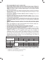
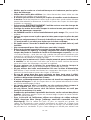
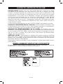
• An extension cord must have adequate wire size (AWG or American Wire
Gauge) for safety. The smaller the gauge number of the wire, the greater the
capacity of the cable, that is 16 gauge has more capacity than 18 gauge. An
undersized cord will cause a drop in line voltage resulting in loss of power and
overheating. When using more than one extension to make up the total length,
be sure each individual extension contains at least the minimum wire size. The
following table shows the correct size to use depending on cord length and
nameplate ampere rating. If in doubt, use the next heavier gauge. The smaller the
gauge number, the heavier the cord.
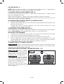
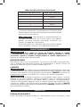
Minimum Gauge for Cord Sets
Ampere Rating
Volts Total Length of Cord in Feet (meters)
120V 25 (7.6) 50 (15.2) 100 (30.5) 150 (45.7)
240V 50 (15.2) 100 (30.5) 200 (61.0) 300 (91.4)
More
Than
Not More
Than
AWG
0 6 18 16 16 14
6 10 18 16 14 12
10 12 16 16 14 12
12 16 14 12 Not Recommended
WARNING
ALWAYS use safety glasses. Everyday eyeglasses are NOT safety
glasses. Also use face or dust mask if cutting operation is dusty. ALWAYS WEAR
CERTIFIED SAFETY EQUIPMENT:
• ANSI Z87.1 eye protection (CAN/CSA Z94.3),
• ANSI S12.6 (S3.19) hearing protection,

6 - ENG
• NIOSH/OSHA/MSHA respiratory protection.
WARNING
Some dust created by power sanding, sawing, grinding, drilling,
and other construction activities contains chemicals known to the State of California
to cause cancer, birth defects or other reproductive harm. Some examples of these
chemicals are:
• lead from lead-based paints,
• crystalline silica from bricks and cement and other masonry products, and
• arsenic and chromium from chemically-treated lumber.
Your risk from these exposures varies, depending on how often you do this type of
work. To reduce your exposure to these chemicals: work in a well ventilated area, and
work with approved safety equipment, such as those dust masks that are specially
designed to filter out microscopic particles.
• Avoid prolonged contact with dust from power sanding, sawing, grinding,
drilling, and other construction activities. Wear protective clothing and
wash exposed areas with soap and water. Allowing dust to get into your
mouth, eyes, or lay on the skin may promote absorption of harmful chemicals.
WARNING
Use of this tool can generate and/or disperse dust, which may cause
serious and permanent respiratory or other injury. Always use NIOSH/OSHA approved
respiratory protection appropriate for the dust exposure. Direct particles away from
face and body.
WARNING
Always wear proper personal hearing protection that conforms
to ANSI S12.6 (S3.19) during use. Under some conditions and duration of use, noise
from this product may contribute to hearing loss.
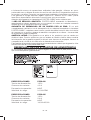
• The label on your tool may include the following symbols. The symbols and their
definitions are as follows:
V ................... volts A ......................amperes
Hz ................. hertz W ..................... watts
min ............... minutes
or AC ..........alternating
or DC ... direct current current
.................Class I Construction or AC/DC ...alternating or
.....................
(grounded) direct current
................. Class II Construction
n
o ....................no load
(double insulated) speed
…/min .......... per minute
n ......................rated speed
BPM ............. beats per minute
.....................earthing
IPM ...............impacts per minute terminal
RPM ............. revolutions per
..................... safety alert
minute symbol
sfpm ............. surface feet per minute
SAVE THESE INSTRUCTIONS
MOTOR
Be sure your power supply agrees with the nameplate marking. Voltage decrease of
more than 10% will cause loss of power and overheating. PORTER-CABLE tools are
factory tested; if this tool does not operate, check power supply.
NOTICE:
Do not operate your tool on a current on which the voltage is not
within correct limits. Do not operate tools rated A.C. only on D.C. current. To do so
may seriously damage the tool.

7 - ENG
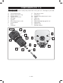
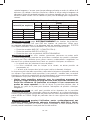
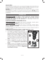
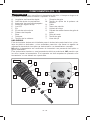
COMPONENTS (FIG. 1, 2)
WARNING
Never modify the power tool or any part of it. Damage or personal
injury could result.
A. Quick release tabs
B. Depth adjustment ring
C. On/off switch
D. Spindle lock button
E. LED light
F. Spindle
G. Micro adjustment scale
H. Locking lever
I. Base
J. Subbase
K. Sub-base screws
L. Guide pins
M. Locking lever adjustment screw
N. Collet
O. Collet nut
P. Motor unit
Q. Roller bearing/edge guide slot
R. Edge guide
S. Guide screw
T. Spindle wrench
FIG. 1
D
C
B
G
F
E
P
O
K
K
Q
J
N
O

8 - ENG
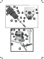
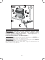
FIG. 2
A
L
S
M
I
T
J
R
H
INTENDED USE
This laminate trimmer is designed for professional flush and bevel trimming of
laminated plastics and other similar materials that have a bonding agent too hard to
be trimmed with ordinary tools.
DO NOT use under wet conditions or in presence of flammable liquids or gases.
This laminate trimmer is a professional power tool. DO NOT let children come into
contact with the tool. Supervision is required when inexperienced operators use this
tool.
OPERATION
WARNING
To reduce the risk of injury, turn unit off and disconnect it from
power source before installing and removing accessories, before adjusting or
when making repairs. An accidental start-up can cause injury.
PROPER HAND POSITION (FIG. 6)
WARNING
To reduce the risk of serious personal injury, ALWAYS use proper
hand position as shown.
WARNING
To reduce the risk of serious personal injury, ALWAYS hold securely
in anticipation of a sudden reaction.
Proper hand position requires one hand on the motor base with the other hand on
the motor cap.
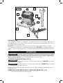
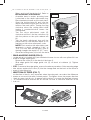
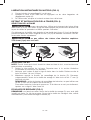
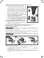
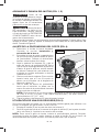
INSERTING THE MOTOR INTO THE FIXED BASE (FIG. 1–3)
1. Open the locking lever (H) on the base.

9 - ENG
2. If the depth adjustment ring (B) is not on the motor,
FIG. 3
B
A
H
L
thread the depth adjustment ring (B) onto the
motor until the ring is positioned as shown. Insert
the motor into the base by aligning the groove in
the back of the motor with the guide pins (L) on the
base. Slide the motor down until the depth
adjustment ring (B) snaps into place.
3. Adjust the depth of cut by turning the depth
adjustment ring (B). Refer to Adjusting the Depth
of Cut.
4. Close the locking lever (H) when the desired depth
is achieved. For information on setting the cutting
depth, Refer to Adjusting the Depth of Cut.
MOTOR QUICK RELEASE (FIG. 3)
1. Open the locking lever (H) on the base.
2. Grasp the base with one hand, depressing both
quick release tabs (A).
3. With the other hand, grasp and pull motor from the
base.
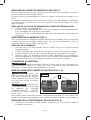
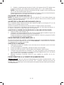
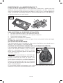
BIT INSTALLATION AND REMOVAL (FIG. 4)
SELECTING THE BIT
WARNING
Projectile hazard. Only use bits with 1/4" (6.4 mm) shanks. Smaller
shank bits will not be secure and could become loose during operation.
These laminate trimmers are equipped with a 1/4" (6.4mm) diameter collet which accepts
bits having 1/4" (6.4mm) diameter shanks. Bits are available as an accessory.
WARNING
Do not use bits with a diameter in excess of 1" (25.4mm) in
this tool.
FIG. 4
D
F
T
INSTALLING THE BIT
NOTE: The bit shank and chuck should be clean and free of dust, wood residue and
grease before assembling.
1. Remove the motor unit from the base. Refer to Motor Quick Release (if needed).
2. Clean and insert the bit shank into the collet until the end of the shank bottoms.
Then withdraw the bit approximately 1/16" (1.6mm).
3. Press and hold the spindle lock button (D). Tighten the collet nut securely with the
supplied17 mm open-end wrench (T).
NOTE: As an alternative to the spindle lock button, a thin 10 mm wrench can be
used on the flats of the spindle (F).
To remove the bit, reverse the procedure. If the bit will not remove easily, lightly tap
the bit shank with a wrench.

10 - ENG
COLLETS (FIG. 1)
NOTE: Never tighten the collet nut (O) without first installing a bit in it. Tightening an
empty collet nut, even by hand, can damage the collet (N).
LOCKING LEVER ADJUSTMENT (FIG. 2)
Excessive force should not be used to clamp the locking lever (H). Using excessive
force may damage the base.
When the locking lever is clamped, the motor should not move in the base.
Adjustment is needed if the locking lever will not clamp without excessive force or if the
motor moves in the base after clamping.
ADJUSTING THE LOCKING LEVER’S CLAMPING FORCE
1. Open the locking lever (H).
2. Using a 2.5 mm hex wrench (not included) turn the locking lever adjustment screw
(M) in small increments.
Turning the screw clockwise tightens the lever, while turning the screw
counterclockwise loosens the lever.
CENTERING THE SUBBASE (FIG. 1)
If you need to adjust, change, or replace the subbase, a centering tool is recommended.
Refer to Accessories. The centering tool consists of a cone and a pin.
ADJUSTING THE SUBBASE
1. Loosen but do not remove the subbase screws (K) so the subbase moves freely.
2. Insert the pin into the collet and tighten the collet nut.
3. Insert the motor into the base and clamp the locking lever on the base.
4. Place a centering cone tool, available as an accessory at additional cost, on the
pin and lightly press down on the cone until it stops. This will center the subbase.
5. While holding down on the cone, tighten the subbase screws (K).
CONNECTING TO POWER SOURCE
CAUTION
Before connecting tool to power source, check to see that the switch
is in the “OFF” position. Also, check the power circuit to see that it is the same as that
shown on specification plate of the tool.
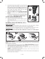
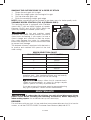
STARTING AND STOPPING THE MOTOR (FIG. 1, 5)
CAUTION
Before starting
the tool, clear the work area of all
foreign objects. Also keep firm grip
on tool to resist starting torque.
CAUTION
To avoid personal
injury and/or damage to finished
work, always allow the power unit
to come to a COMPLETE STOP
before putting the tool down.
To turn unit on, pull the on/off
switch (C) up. To turn the unit off, depress the switch back down into the motor housing.
Refer to Figure 5.
FIG. 5
C

11 - ENG
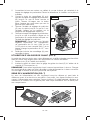
ADJUSTING THE DEPTH OF CUT (FIG. 6)
1. Select and install the desired bit. Refer to
Bit Installation and Removal.
2. Assemble base to motor, ensuring base
is attached to the depth adjustment ring.
Place laminate trimmer on the work piece.
3. Open the locking lever (H) and turn the
depth adjustment ring (B) until the bit just
touches the work piece. Turning the ring
clockwise raises the cutting head while
turning it counterclockwise lowers the
cutting head.
4. Turn the micro adjustment scale (G)
clockwise until the 0 on the scale lines up
with the pointer on the quick release tab
(A).
5. Turn the depth adjustment ring until the
pointer lines up with desired depth of cut
marking on the micro adjustment scale.
NOTE: Each mark on the adjustable scale
represents a depth change of 1/64" or
.015" (0.4mm) and one full (360º) turn of
the ring changes the depth 0.5" (12.7mm).
6. Close the locking lever (H) to lock the base.
USING AN EDGE GUIDE (FIG. 2)
An edge guide is included with your laminate trimmer for use with non-piloted bits on
curved or straight applications.
1. Remove the screw (S) in the back of the base (I).
2. Slide edge guide into edge guide slot (Q) on back of subbase (J). Tighten
hardware.
NOTE: To remove the edge guide, reverse the above procedure. After removing edge
guide, always replace the screw (S) into the storage hole on the back of the base to
prevent it from being lost.
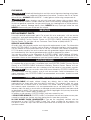
DIRECTION OF FEED (FIG. 7)
The direction of feed is very important when trimming and can make the difference
between a successful job and a ruined project. The figures show the proper direction
of feed for some typical cuts. A general rule to follow is to move the laminate trimmer
in a counterclockwise direction on an outside cut and a clockwise direction on an
inside cut.
1
4
3
2
FIG. 7
FIG. 6
G
B
H

12 - ENG
SHAPING THE OUTSIDE EDGE OF A PIECE OF STOCK
1. Shape the end grain, left to right
2. Shape the straight grain side moving left to right
3. Cut the other end grain side
4. Finish the remaining straight grain edge
NOTE: Make several light passes instead of one heavy pass for better quality work.
VARIABLE SPEED CONTROL (FIG. 8) (PCE6435 ONLY)
This laminate trimmer is equipped with a variable
speed dial (T) with an infinite number of speeds
between 16,000 and 30,000 RPM. Adjust the
speed by turning the variable speed dial (T).
NOTICE:
In low and medium speed
operation, the speed control prevents the motor
speed from decreasing. If you expect to hear a
speed change and continue to load the motor,
you could damage the motor by overheating.
Reduce the depth of cut and/or slow the feed rate
to prevent tool damage.
The laminate trimmer is equipped with electronics
to monitor and maintain the speed of the tool
while cutting.
SPEED SELECTION CHART
DIAL SETTING APPROX. RPM
1 16,000
2 19,300
3 21,400
4 23,700
5 26,400
6 30,000
The speeds in this chart are approximate and are for
reference only. Your laminate trimmer may not exactly
produce the speed listed for the dial setting.
WARNING
Always follow the bit manufacturer’s
speed recommendations as some bit designs require
specific speeds for safety or performance.
If you are unsure of the proper speed or are experiencing
any type of problem, contact the bit manufacturer.
MAINTENANCE
WARNING
To reduce the risk of injury, turn unit off and disconnect it from
power source before installing and removing accessories, before adjusting or
when making repairs. An accidental start-up can cause injury.
REPAIRS
For assistance with your tool, visit our website at www.portercable.com for a list of service
centers, or call the PORTER-CABLE Customer Care Center at (888) 848-5175.
FIG. 8
T

13 - ENG
CLEANING
WARNING
Periodically blowing dust and chips out of the motor housing using clean,
dry compressed air is a suggested maintenance procedure. To reduce the risk of serious
personal injury,
ALWAYS wear ANSI Z87.1 safety glasses while using compressed air.
WARNING
When cleaning, use only mild soap and a damp cloth on plastic parts.
Many household cleaners contain chemicals which could seriously damage plastic. Also,
do not use gasoline, turpentine, lacquer, paint thinner, dry cleaning fluids or similar products
which may seriously damage plastic parts.
NEVER let any liquid get inside the tool;
NEVER
immerse any part of the tool into a liquid.
SERVICE
REPLACEMENT PARTS
Use only identical replacement parts. For a parts list or to order parts, visit our service
website at servicenet.portercable.com. You can also order parts from your nearest
PORTER-CABLE Factory Service Center or PORTER-CABLE Authorized Warranty
Service Center. Or, you can call our Customer Care Center at (888) 848-5175.
SERVICE AND REPAIRS
All quality tools will eventually require servicing and/or replacement of parts. For information
about PORTER-CABLE, its factory service centers or authorized warranty service centers,
visit our website at www.portercable.com or call our Customer Care Center at (888) 848-
5175. All repairs made by our service centers are fully guaranteed against defective material
and workmanship. We cannot guarantee repairs made or attempted by others.
You can also write to us for information at PORTER-CABLE, 4825 Highway 45 North,
Jackson, Tennessee 38305 - Attention: Product Service. Be sure to include all of the
information shown on the nameplate of your tool (model number, type, serial number, etc.).
ACCESSORIES
A complete line of accessories is available from your PORTER-CABLE Factory Service
Center or a PORTER-CABLE Authorized Warranty Service Center. Please visit our
Web Site www.portercable.com for a catalog or for the name of your nearest supplier.
WARNING
Since accessories other than those offered by PORTER-CABLE have
not been tested with this product, use of such accessories could be hazardous. For
safest operation, only PORTER-CABLE recommended accessories should be used
with this product.
THREE YEAR LIMITED WARRANTY
PORTER-CABLE will repair, without charge, any defects due to faulty materials or
workmanship for three years from the date of purchase. This warranty does not cover
part failure due to normal wear or tool abuse. For further detail of warranty coverage
and warranty repair information, visit www.portercable.com or call (888) 848-5175. This
warranty does not apply to accessories or damage caused where repairs have been made
or attempted by others. This warranty gives you specific legal rights and you may have other
rights which vary in certain states or provinces.
In addition to the warranty, PORTER-CABLE tools are covered by our:
1 YEAR FREE SERVICE: PORTER-CABLE will maintain the tool and replace worn parts
caused by normal use, for free, any time during the first year after purchase.
90 DAY MONEY BACK GUARANTEE: If you are not completely satisfied with the
performance of your PORTER-CABLE Power Tool, Laser, or Nailer for any reason, you
can return it within 90 days from the date of purchase with a receipt for a full refund – no
questions asked.

14 - ENG
LATIN AMERICA: This warranty does not apply to products sold in Latin America. For
products sold in Latin America, see country specific warranty information contained in the
packaging, call the local company or see website for warranty information.
To register your tool for warranty service visit our website at www.portercable.com.
WARNING LABEL REPLACEMENT
If your warning labels become illegible or are missing, call (888) 848-5175 for a free
replacement.

15 - FR
MESURES DE SÉCURITÉ - DÉFINITIONS
DANGER
indique une situation dangereuse imminente qui, si elle n’est pas
évitée, causera la mort ou des blessures graves.
AVERTISSMENT
indique une situation potentiellement dangereuse qui, si
elle n’est pas évitée, pourrait se solder par un décès ou des blessures graves.
ATTENTION
indique une situation potentiellement dangereuse qui, si elle
n’est pas évitée pourrait se solder par des blessures mineures ou modérées.
AVIS:
indique une pratique ne posant aucun risque de dommages
corporels mais qui par contre, si rien n’est fait pour l’éviter, pourrait poser des
risques de dommages matériels.
AVERTISSMENT
Afin de réduire le risque de blessures, lire le mode
d’emploi de l’outil.
AVERTISSEMENTS DE SÉCURITÉ GÉNÉRAUX
POUR LES OUTILS ÉLECTRIQUES
Lire tous les avertissements de sécurité
et les directives. Le non-respect des
avertissements et des directives pourrait se
solder par un choc électrique, un incendie et/
ou une blessure grave.
CONSERVER TOUS LES AVERTISSEMENTS ET
TOUTES LES DIRECTIVES
POUR UN USAGE ULTÉRIEUR
Le terme « outil électrique » cité dans les avertissements se rapporte à votre outil
électrique à alimentation sur secteur (avec fil) ou par piles (sans fil).
1) SÉCURITÉ DU LIEU DE TRAVAIL
a) Tenir l’aire de travail propre et bien éclairée. Les lieux encombrés ou
sombres sont propices aux accidents.
b) Ne pas faire fonctionner d’outils électriques dans un milieu déflagrant,
tel qu’en présence de liquides, de gaz ou de poussières inflammables.
Les outils électriques produisent des étincelles qui pourraient enflammer la
poussière ou les vapeurs.
c) Éloigner les enfants et les personnes à proximité pendant l’utilisation
d’un outil électrique. Une distraction pourrait en faire perdre la maîtrise à
l’utilisateur.
2) SÉCURITÉ EN MATIÈRE D’ÉLECTRICITÉ
a) Les fiches des outils électriques doivent correspondre à la prise. Ne
jamais modifier la fiche d’aucune façon. Ne jamais utiliser de fiche
d’adaptation avec un outil électrique mis à la terre. Le risque de choc
électrique sera réduit par l’utilisation de fiches non modifiées correspondant à la
prise.
b) Éviter tout contact physique avec des surfaces mises à la terre comme
des tuyaux, des radiateurs, des cuisinières et des réfrigérateurs. Le
risque de choc électrique est plus élevé si votre corps est mis à la terre.

16 - FR
c) Ne pas exposer les outils électriques à la pluie ou à l’humidité. La
pénétration de l’eau dans un outil électrique augmente le risque de choc
électrique.
d) Ne pas utiliser le cordon de façon abusive. Ne jamais utiliser le cordon
pour transporter, tirer ou débrancher un outil électrique. Tenir le cordon
éloigné de la chaleur, de l’huile, des bords tranchants et des pièces
mobiles. Les cordons endommagés ou enchevêtrés augmentent les risques de
choc électrique.
e) Pour l’utilisation d’un outil électrique à l’extérieur, se servir d’une
rallonge convenant à cette application. L’utilisation d’une rallonge conçue
pour l’extérieur réduira les risques de choc électrique.
f) S’il est impossible d’éviter l’utilisation d’un outil électrique dans un
endroit humide, brancher l’outil dans une prise ou sur un circuit
d’alimentation dotés d’un disjoncteur de fuite à la terre (GFCI). L’utilisation
de ce type de disjoncteur réduit les risques de choc électrique.
3) SÉCURITÉ PERSONNELLE
a) Être vigilant, surveiller le travail effectué et faire preuve de jugement
lorsqu’un outil électrique est utilisé. Ne pas utiliser d’outil électrique
en cas de fatigue ou sous l’influence de drogues, d’alcool ou de
médicaments. Un simple moment d’inattention en utilisant un outil électrique
peut entraîner des blessures corporelles graves.
b) Utiliser des équipements de protection individuelle. Toujours porter
une protection oculaire. L’utilisation d’équipements de protection comme un
masque antipoussière, des chaussures antidérapantes, un casque de sécurité
ou des protecteurs auditifs lorsque la situation le requiert réduira les risques de
blessures corporelles.
c) Empêcher les démarrages intempestifs. S’assurer que l’interrupteur
se trouve à la position d’arrêt avant de relier l’outil à une source
d’alimentation et/ou d’insérer un bloc-piles, de ramasser ou de
transporter l’outil. Transporter un outil électrique alors que le doigt repose sur
l’interrupteur ou brancher un outil électrique dont l’interrupteur est à la position
de marche risque de provoquer un accident.
d) Retirer toute clé de réglage ou clé avant de démarrer l’outil. Une clé ou
une clé de réglage attachée à une partie pivotante de l’outil électrique peut
provoquer des blessures corporelles.
e) Ne pas trop tendre les bras. Conserver son équilibre en tout temps. Cela
permet de mieux maîtriser l’outil électrique dans les situations imprévues.
f) S’habiller de manière appropriée. Ne pas porter de vêtements amples
ni de bijoux. Garder les cheveux, les vêtements et les gants à l’écart
des pièces mobiles. Les vêtements amples, les bijoux ou les cheveux longs
risquent de rester coincés dans les pièces mobiles.
g) Si des composants sont fournis pour le raccordement de dispositifs
de dépoussiérage et de ramassage, s’assurer que ceux-ci sont bien
raccordés et utilisés. L’utilisation d’un dispositif de dépoussiérage peut réduire
les dangers engendrés par les poussières.
4) UTILISATION ET ENTRETIEN D’UN OUTIL ÉLECTRIQUE
a) Ne pas forcer un outil électrique. Utiliser l’outil électrique approprié à
l’application. L’outil électrique approprié effectuera un meilleur travail, de façon
plus sûre et à la vitesse pour laquelle il a été conçu.
b) Ne pas utiliser un outil électrique dont l’interrupteur est défectueux.
Tout outil électrique dont l’interrupteur est défectueux est dangereux et doit être
réparé.

17 - FR
c) Débrancher la fiche de la source d’alimentation et/ou du bloc-piles de
l’outil électrique avant de faire tout réglage ou changement d’accessoire
ou avant de ranger l’outil. Ces mesures préventives réduisent les risques de
démarrage accidentel de l’outil électrique.
d) Ranger les outils électriques hors de la portée des enfants et ne
permettre à aucune personne n’étant pas familière avec un outil
électrique ou son mode d’emploi d’utiliser cet outil. Les outils électriques
deviennent dangereux entre les mains d’utilisateurs inexpérimentés.
e) Entretien des outils électriques. Vérifier si les pièces mobiles sont mal
alignées ou coincées, si des pièces sont brisées ou présentent toute
autre condition susceptible de nuire au bon fonctionnement de l’outil
électrique. En cas de dommage, faire réparer l’outil électrique avant
toute nouvelle utilisation. Beaucoup d’accidents sont causés par des outils
électriques mal entretenus.
f) S’assurer que les outils de coupe sont aiguisés et propres. Les outils de
coupe bien entretenus et affûtés sont moins susceptibles de se coincer et sont
plus faciles à maîtriser.
g) Utiliser l’outil électrique, les accessoires, les forets, etc. conformément
aux présentes directives en tenant compte des conditions de travail et
du travail à effectuer. L’utilisation d’un outil électrique pour toute opération
autre que celle pour laquelle il a été conçu est dangereuse.
5) RÉPARATION
a) Faire réparer l’outil électrique par un réparateur professionnel en
n’utilisant que des pièces de rechange identiques. Cela permettra de
maintenir une utilisation sécuritaire de l’outil électrique.
RÈGLES DE SÉCURITÉ SPÉCIFIQUE
RÈGLES DE SÉCURITÉ ADDITIONNELLES PROPRES AUX
DÉTOUREUSES À STRATIFIÉS
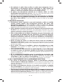
• Tenir l’outil électrique par ses parties isolées car l’organe de coupe pour-
rait entrer en contact avec son cordon. Couper un fil sous tension pourra
mettre les parties métalliques exposées de l’outil électrique sous tension et électro-
cuter l’utilisateur.
• Utiliser des serre-joints, ou tout autre moyen, pour fixer et immobiliser le
matériau sur une surface stable. Tenir la pièce à la main ou contre son corps
offre une stabilité insuffisante qui pourrait vous en faire perdre le contrôle.
• Suivre systématiquement les recommandations du fabricant de forets
quant à la vitesse, car certains forets ont été conçus pour des vitesses
spécifiques pour des raisons de sécurité ou de performances. Si vous n’êtes
pas sûr de la vitesse correcte ou rencontrez un problème quelconque, veuillez con-
tacter le fabricant du foret.
• NE DÉCOUPER AUCUN MÉTAL.
• Maintenir les poignées et les surfaces de prises propres et sèches,
exemptes d’huile ou de graisse. Cela permettra un meilleur contrôle de l’outil.
• Maintenir une prise ferme sur la détoureuse à stratifiés, à deux mains, pour
résister à tout couple de démarrage.
• Garder les mains éloignées des zones de coupe. Ne jamais passer les
doigts sous le matériau pour quelque raison que ce soit. Maintenir fermement
la base de la détoureuse à stratifiés tout contre la pièce pendant la coupe. Ces
précautions réduiront tout risque de dommages corporels.
• Ne pas faire tourner le bloc-moteur tant que l’appareil n’est pas inséré
dans la base. Le moteur n’a pas été conçu pour être tenu manuellement.
• Maintenir une pression de coupe constante. Ne pas surcharger le moteur.

18 - FR
• Vérifier que le cordon ne s’enchevêtrera pas et n’entravera pas les opéra-
tions de détourage.
• Utilisez des fraises bien affûtées. Les fraises émoussées feront dévier ou caler
la détoureuse à stratifiés sous la pression.
• S’assurer que la fraise ne touche pas la pièce à travailler avant de démarrer
le moteur. Le fait de la mettre en contact avec la pièce alors que le moteur démarre
pourra faire rebondir la détoureuse à stratifiés et poser des risques de dommages
matériels ou corporels.
• Déconnecter SYSTÉMATIQUEMENT l’outil du secteur avant de changer de
fraise ou d’effectuer tout réglage.
• Protéger les mains de la fraise lorsque le moteur tourne pour prévenir tout
risque de dommages corporels.
• Ne JAMAIS toucher la fraise immédiatement après usage. Elle pourrait être
brûlante.
• Laisser un espace sous la pièce pour la fraise pour couper la pièce de part
en part.
• Resserrer soigneusement l’écrou de la douille de serrage à l’aide de la clé
(17mm) fournie à cet effet pour éviter que la fraise ne dérape.
• Ne jamais serrer l’écrou de la douille de serrage sans qu’une fraise n’y soit
installée.
• Non recommandé pour être utilisé avec une table à toupie.
• Éviter tout usinage tangentiel en avalant (couper dans la direction opposée
à celle indiquée en figure8). L’usinage tangentiel en avalant augmente les
risques de perdre le contrôle de l’outil et de dommages corporels. Lorsque
c’est nécessaire (ex.: recul dans un coin), prendre des précautions extrêmes pour
maintenir le contrôle de la détoureuse. Effectuer des coupes plus réduites et retirer
un minimum de matériau à chaque passage.
• S’assurer que le moteur est à l’arrêt complet avant de poser la détoureuse
à stratifiés. Le fait de poser l’outil alors que la tête de fraise continue de tourner
pose des risques de dommages corporels ou matériels.
• Ne pas appuyer sur le bouton de verrouillage de la broche lorsque le
moteur tourne. Cela pourrait endommager le verrouillage de broche.
• Ne pas utiliser des outils exclusivement CA avec un bloc d’alimentation
CC. Même si l’outil semble fonctionner, les composants électriques d’un outil CA
pourront dysfonctionner et poser des risques à l’utilisateur.
• En cas de coupe dans des murs existants ou dans toute zone à visibi-
lité réduite où des fils électriques pourraient se trouver, déconnecter tout
fusible ou disjoncteur alimentant la zone.
• S’assurer systématiquement que la surface de travail ne comporte ni clou
ni objets étrangers. Le fait de couper dans un clou pourra faire rebondir la fraise
ou l’outil et endommager la fraise.
• Ne jamais poser la pièce à travailler sur des surfaces dures comme le
béton, la pierre, etc. Une fraise dépassant pourra faire rebondir l’outil.
• Ne pas laisser l’outil tourner seul. Ne laisser fonctionner un outil que
lorsqu’il est maintenu à la main.
• Prendre des précautions à proximité des évents, car ils cachent des pièces
mobiles. Vêtements amples, bijoux ou cheveux longs risquent de rester coincés
dans ces pièces mobiles.
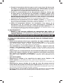
• Pour la sécurité de l’utilisateur, utiliser une rallonge de calibre adéquat
(AWG, American Wire Gauge [calibrage américain normalisé des fils
électriques]). Plus le calibre est petit, et plus sa capacité est grande. Un
calibre16, par exemple, a une capacité supérieure à un calibre18. L’usage d’une
rallonge de calibre insuffisant causera une chute de tension qui entraînera perte
de puissance et surchauffe. Si plus d’une rallonge est utilisée pour obtenir une

19 - FR
certaine longueur, s’assurer que chaque rallonge présente au moins le calibre de fil
minimum. Le tableau ci-dessous illustre les calibres à utiliser selon la longueur de
rallonge et l’intensité nominale indiquée sur la plaque signalétique. En cas de doute,
utiliser le calibre suivant. Plus le calibre est petit, plus la rallonge peut supporter de
courant.
Calibres minimaux des rallonges
Intensité (en ampères)
volts Longueur totale de cordon en mètres
(pieds)
120 V 7,6 (25) 15,2 (50) 30,5 (100) 45,7 (150)
240 V 15,2 (50) 30,5 (100) 61,0 (200) 91,4 (300)
Supérieur à Inférieur à AWG
0 6 18 16 16 14
610 18161412
10 12 16 16 14 12
12 16 14 12 Non recommandé
AVERTISSMENT
porter SYSTEMATIQUEMENT des lunettes de protection.
Les lunettes courantes NE sont PAS des lunettes de protection. Utiliser aussi
un masque antipoussières si la découpe doit en produire beaucoup. PORTER
SYSTÉMATIQUEMENT UN ÉQUIPEMENT DE SÉCURITÉ HOMOLOGUÉ:
• Protection oculaire ANSI Z87.1 (CAN/CSA Z94.3);
• Protection auditive ANSI S12.6 (S3.19);
• Protection des voies respiratoires NIOSH/OSHA/MSHA.
AVERTISSMENT
les scies, meules, ponceuses, perceuses ou autres outils
de construction peuvent produire des poussières contenant des produits chimiques
reconnus par l’État californien pour causer cancers, malformations congénitales ou
être nocifs au système reproducteur. Parmi ces produits chimiques, on retrouve:
• Le plomb dans les peintures à base de plomb;
• La silice cristallisée dans les briques et le ciment, ou autres produits de
maçonnerie; et
• L’arsenic et le chrome dans le bois ayant subi un traitement chimique.
Le risque associé à de telles expositions varie selon la fréquence à laquelle on effectue
ces travaux. Pour réduire toute exposition à ces produits: travailler dans un endroit
bien aéré, en utilisant du matériel de sécurité homologué, tel un masque antipoussières
spécialement conçu pour filtrer les particules microscopiques.
• Limiter toute exposition prolongée avec les poussières provenant du
ponçage, sciage, meulage, perçage ou toute autre activité de construction.
Porter des vêtements de protection et nettoyer à l’eau savonneuse les
parties du corps exposées. Le fait de laisser la poussière pénétrer dans la
bouche, les yeux ou la peau peut favoriser l’absorption de produits chimiques
dangereux.
AVERTISSMENT
cet outil peut produire et/ou répandre de la poussière
susceptible de causer des dommages sérieux et permanents au système respiratoire.
Utiliser systématiquement un appareil de protection des voies respiratoires homologué
par le NIOSH ou l’OSHA. Diriger les particules dans le sens opposé au visage et au
corps.
AVERTISSMENT
pendant l’utilisation, porter systématiquement une
protection auditive individuelle adéquate homologuée ANSI S12.6 (S3.19).
Sous certaines conditions et suivant la durée d’utilisation, le bruit émanant de ce
produit pourrait contribuer à une perte de l’acuité auditive.

20 - FR
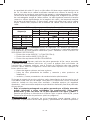
• L’étiquette apposée sur votre outil peut inclure les symboles suivants. Les symboles
et leur définition sont indiqués ci-après:
V ................... volts A .....................ampères
Hz ................. hertz W ....................watts
min ............... minutes
ou AC .......courant alternatif
ou DC ... courant continu ou AC/DC .courant alternatif
................. classe I fabrication ou continu
(mis à la terre)
n
o ...................vitesse à vide
................. fabrication n .....................vitesse nominale
classe II (double
...................borne de terre
isolation)
....................symbole
…/min .......... par minute d’avertissement
IPM ............... impacts par SPM (FPM) .....fréquence par
minute minute
BPM ............. battements par r/min ...............tours par
minute minute
sfpm ............. pieds linéaires
par minute (plpm)
CONSERVER CES DIRECTIVES
MOTEUR
S’assurer que le bloc d’alimentation est compatible avec l’inscription de la plaque
signalétique.Une diminution de tension de plus de 10 % provoquera une perte de
puissance et une surchauffe. Les outils PORTER-CABLE sont testés en usine; si cet
outil ne fonctionne pas, vérifier l’alimentation électrique.
AVIS:
Ne pas utiliser l’outil relié à un courant pour lequel la tension n’est pas
dans les limites correctes. Ne pas faire fonctionner des outils à courant alternatif (c.a.)
sur un courant continu (c.c.). Un tel branchement pourrait endommager gravement
l’outil.
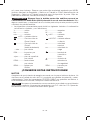
COMPONENTS (FIG. 1, 2)
AVERTISSMENT
ne jamais modifier l’outil électrique ni aucun de ses
composants, car il y a risques de dommages corporels ou matériels.
A. Languettes de dégagement rapide
B. Bague de réglage de profondeur
C. Interrupteur marche/arrêt
D. Bouton de blocage de l’arbre
E. Voyant DEL
F. Broche
G. Échelle de réglage de précision
H. Levier de verrouillage
I. Base
J. Semelle
K. Vis de la semelle
L. Tenons de guidage
M. Vis de réglage du levier de verrouillage
N. Douille de serrage
O. Écrou de la douille de serrage
P. Bloc-moteur
Q. Roulements des galets/gorge du
guide de chant
R. Guide de chant
S. Vis de guide
T. Clé à broche
La page est en cours de chargement...
La page est en cours de chargement...
La page est en cours de chargement...
La page est en cours de chargement...
La page est en cours de chargement...
La page est en cours de chargement...
La page est en cours de chargement...
La page est en cours de chargement...
La page est en cours de chargement...
La page est en cours de chargement...
La page est en cours de chargement...
La page est en cours de chargement...
La page est en cours de chargement...
La page est en cours de chargement...
La page est en cours de chargement...
La page est en cours de chargement...
La page est en cours de chargement...
La page est en cours de chargement...
La page est en cours de chargement...
La page est en cours de chargement...
La page est en cours de chargement...
La page est en cours de chargement...
La page est en cours de chargement...
La page est en cours de chargement...
La page est en cours de chargement...
La page est en cours de chargement...
La page est en cours de chargement...
La page est en cours de chargement...
-
 1
1
-
 2
2
-
 3
3
-
 4
4
-
 5
5
-
 6
6
-
 7
7
-
 8
8
-
 9
9
-
 10
10
-
 11
11
-
 12
12
-
 13
13
-
 14
14
-
 15
15
-
 16
16
-
 17
17
-
 18
18
-
 19
19
-
 20
20
-
 21
21
-
 22
22
-
 23
23
-
 24
24
-
 25
25
-
 26
26
-
 27
27
-
 28
28
-
 29
29
-
 30
30
-
 31
31
-
 32
32
-
 33
33
-
 34
34
-
 35
35
-
 36
36
-
 37
37
-
 38
38
-
 39
39
-
 40
40
-
 41
41
-
 42
42
-
 43
43
-
 44
44
-
 45
45
-
 46
46
-
 47
47
-
 48
48


Porter Cable PCE6430 Manuel utilisateur
- Catégorie
- Outils électroportatifs
- Taper
- Manuel utilisateur
- Ce manuel convient également à
dans d''autres langues
- English: Porter Cable PCE6430 User manual
- español: Porter Cable PCE6430 Manual de usuario