Simplicity 040378-02 Manuel utilisateur
- Catégorie
- Groupes électrogènes
- Taper
- Manuel utilisateur

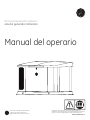
GE Home Generator Systems
Generator System
Operator’s Manual
Copyright ©. All rights reserved. No part of this material may be
reproduced or transmitted in any form without the express written
permission of Briggs & Stratton Power Products Group, LLC.
is a trademark of General Electric Company
and is under license by Briggs & Stratton
Power Products Group, LLC.
314673 Revision F

2
Thank you for purchasing this quality-built GE home generator. We’re pleased that you’ve placed your confidence in
the GE brand. When operated and maintained according to the instructions in this manual, your home generator will
provide many years of dependable service.
This manual contains safety information to make you aware of the hazards and risks associated with home standby
generators and how to avoid them. Because we do not necessarily know all the applications this equipment could
be used for, it is important that you read and understand these instructions thoroughly before attempting to start or
operate this equipment.
Save these instructions for future reference.
This home standby generator requires professional installation before use. Refer to the separate installation manual
for full information. Your installer should follow the instructions completely.
Where to Find Us
You never have to look far to find GE support and service for your generator. For quick service when you need it, keep
your original receipt with this manual. You may contact Customer Service at (888) 575-8226 between 8:00 AM and 5:00
PM CT., or click on SERVICE & SUPPORT at http://www.gegenerators.com, which provides a list of authorized dealers.
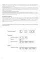
Generator and engine model and serial numbers should be recorded in the installation manual.
DATE OF PURCHASE
GENERATOR
Model Number
Model Number
Model Revision
Serial Number
ENGINE

3
Table of Contents
Safety Rules.....................................................4
Important Safety Instructions .............................................. 4
Installation .....................................................7
For the Home Owner.............................................
7
For the Installing Dealer/Contractor......................................... 7
Owner Orientation......................................................... 8
Generator Location ........................................................ 9
Delivery Inspection ....................................................... 10
Controls ...................................................... 11
Access Panels ............................................................ 13
System Control Panel ..................................................... 15
Operation..................................................... 19
Important Owner’s Considerations ......................................... 19
Automatic Operation ..................................................... 20
Setting Exercise Timer .................................................... 20
Wireless Monitor ......................................................... 21
Maintenance .................................................. 24
Servicing the System...................................................... 24
Service Code Detection System ............................................ 24
Maintenance Schedule . . . . . . . . . . . . . . . . . . . . . . . . . . . . . . . . . . . . . . . . . . . . . . . . . . . . 26
Generator Maintenance................................................... 26
Battery ........................................................27
Electronic Governor.............................................28
Engine Maintenance ...................................................... 29
Adjust Valve Lash...............................................29
Engine Oil................................................................ 30
Service Air Cleaner ....................................................... 31
Fuel System Inspection and Maintenance ................................... 32
Service Spark Plugs ....................................................... 33
Clean Air Cooling System and Oil Cooler Fins................................ 33
When Calling for Assistance ............................................... 33
Storage.................................................................. 33
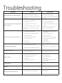
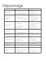
Troubleshooting .............................................. 34
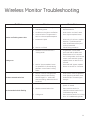
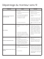
Wireless Monitor Troubleshooting............................... 35
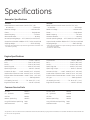
Specifications ................................................. 36
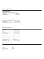
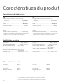
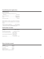
Generator Specifications .................................................. 36
Engine Specifications ..................................................... 36
Common Service Parts .................................................... 36

4
Safety Rules
SAVE THESE INSTRUCTIONS - This manual contains
important instructions that should be followed during
installation and maintenance of the generator and batteries.
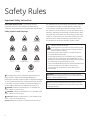
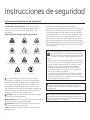
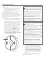
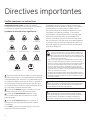
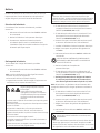
Safety Symbols and Meanings
The safety alert symbol indicates a potential personal
injury hazard. A signal word (DANGER, WARNING, or
CAUTION) is used with the alert symbol to designate a degree
or level of hazard seriousness. A safety symbol may be used
to represent the type of hazard. The signal word NOTICE is
used to address practices not related to personal injury.
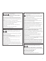
DANGER indicates a hazard which, if not avoided, will
result in death or serious injury.
WARNING indicates a hazard which, if not avoided, could
result in death or serious injury.
CAUTION indicates a hazard which, if not avoided, could
result in minor or moderate injury.
NOTICE addresses practices not related to personal injury.
Important Safety Instructions
The manufacturer cannot possibly anticipate every possible
circumstance that might involve a hazard. The warnings
in this manual, and the tags and decals affixed to the unit
are, therefore, not all-inclusive. If you use a procedure, work
method or operating technique that the manufacturer does
not specifically recommend, you must satisfy yourself that it
is safe for you and others. You must also make sure that the
procedure, work method or operating technique that you
choose does not render the generator system unsafe.
WARNING The engine exhaust from this product contains
chemicals known to the State of California to cause cancer, birth
defects, or other reproductive harm.
WARNING Certain components in this product and related
accessories contain chemicals known to the State of California
to cause cancer, birth defects, or other reproductive harm. Wash
hands after handling.
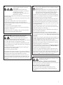
Explosion
Fire
Electrical Shock
Rotating Parts
Hot Surface
Toxic Fumes
Chemical BurnExplosive PressureAuto Start
Lift Hazard
Read Manual
WARNING Running engine gives off carbon monoxide, an
odorless, colorless, poison gas.
Breathing carbon monoxide could result in death, serious
injury, headache, fatigue, dizziness, vomiting, confusion,
seizures, nausea or fainting.
• Operate this product ONLY outdoors in an area that will not
accumulate deadly exhaust gas.
• Keep exhaust gas away from any windows, doors, ventilation
intakes, soffit vents, crawl spaces, open garage doors or other
openings that can allow exhaust gas to enter inside or be drawn
into a potentially occupied building or structure.
• Carbon monoxide detector(s) MUST be installed and maintained
indoors according to the manufacturer’s instructions/
recommendations. Smoke alarms cannot detect carbon
monoxide gas.

5
WARNING Unintentional sparking could cause fire or electric
shock resulting in death or serious injury.
WHEN ADJUSTING OR MAKING REPAIRS TO YOUR GENERATOR
• Disconnect the spark plug wire from the spark plug and place the
wire where it cannot contact spark plug.
WHEN TESTING FOR ENGINE SPARK
• Use approved spark plug tester.
• DO NOT check for spark with spark plug removed.
WARNING Storage batteries give off explosive hydrogen gas
during recharging.
Slightest spark will ignite hydrogen and
cause explosion, resulting in death or
serious injury.
Battery electrolyte fluid contains acid and is extremely caustic.
Contact with battery contents could cause severe chemical burns.
A battery presents a risk of electrical shock and high short circuit
current.
• DO NOT dispose of battery in a fire. Recycle battery.
• DO NOT allow any open flame, spark, heat, or lit cigarette during
and for several minutes after charging a battery.
• DO NOT open or mutilate the battery.
• Wear protective goggles, rubber apron, rubber boots and
rubber gloves.
• Remove watches, rings, or other metal objects.
• Use tools having insulated handles.
WARNING Generator produces hazardous voltage.
Failure to properly ground generator could result
in electrocution.
Failure to isolate generator from utility power could result
in death or serious injury to electric utility workers due to
backfeed of electrical energy.
• When using generator for backup power, notify utility company.
• DO NOT touch bare wires or bare receptacles.
• DO NOT use generator with electrical cords which are worn,
frayed, bare or otherwise damaged.
• DO NOT handle generator or electrical cords while standing in
water, while barefoot, or while hands or feet are wet.
• If you must work around a unit while it is operating, stand on an
insulated dry surface to reduce the risk of a shock hazard.
• DO NOT allow unqualified persons or children to operate or
service generator.
• In case of an accident caused by electrical shock, immediately
shut down the source of electrical power and contact the local
authorities. Avoid direct contact with the victim.
• Despite the safe design of the residential generator, operating
this equipment imprudently, neglecting its maintenance or being
careless could cause possible injury or death.
• Remain alert at all times while working on this equipment.
Never work on the equipment when you are physically or
mentally fatigued.
• Before performing any maintenance on the generator, disconnect
the battery cable indicated by a NEGATIVE, NEG or (-) first. When
finished, reconnect that cable last.
• After your system is installed, the generator may crank and start
without warning any time there is a power failure. To prevent
possible injury, always set the generator’s system switch to OFF,
remove the service disconnect from the disconnect box AND
remove the 15 Amp fuse BEFORE working on the equipment.
WARNING Propane and Natural Gas are extremely flammable
and explosive, which could cause burns, fire or
explosion resulting in death or serious injury.
• Install the fuel supply system according to NFPA 37 and other
applicable fuel-gas codes.
• Before placing the generator into service, the fuel system lines
must be properly purged and leak tested.
• After the generator is installed, you should inspect the fuel
system periodically.
• NO leakage is permitted.
• DO NOT operate engine if smell of fuel is present or other
explosive conditions exist.
• DO NOT smoke around the generator. Wipe up any oil spills
immediately. Ensure that no combustible materials are left in the
generator compartment. Keep the area near the generator clean
and free of debris.

6
WARNING Starter and other rotating parts could entangle
hands, hair, clothing, or accessories resulting in
serious injury.
• NEVER operate generator without protective housings, covers, or
guards in place.
• DO NOT wear loose clothing, jewelry or anything that could be
caught in the starter or other rotating parts.
• Tie up long hair and remove jewelry.
• Before servicing, remove 15 Amp fuse from control panel and
disconnect Negative (NEG or -) battery cable.
CAUTION Installing the 15 Amp fuse could cause the engine
to start at any time without warning resulting in minor or
moderate injury.
• Observe that the 15 Amp fuse has been removed from the control
panel for shipping.
• DO NOT install this fuse until all plumbing and wiring has been
completed and inspected.
CAUTION Excessively high operating speeds could result in
minor injury.
Excessively low speeds impose a heavy load on generator.
• DO NOT tamper with governed speed. Generator supplies correct
rated frequency and voltage when running at governed speed.
• DO NOT modify generator in any way.
NOTICE Improper treatment of generator could damage it and
shorten its life.
• Use generator only for intended uses.
• If you have questions about intended use, contact your
authorized dealer.
• Operate generator only on level surfaces.
• Adequate, unobstructed flow of cooling and ventilating air is
critical for correct generator operation.
• The access panels/door must be installed whenever the unit
is running.
• DO NOT expose generator to excessive moisture, dust, dirt, or
corrosive vapors.
• Remain alert at all times while working on this equipment.
Never work on the equipment when you are physically or
mentally fatigued.
• DO NOT start engine with air cleaner or air cleaner cover removed.
• DO NOT insert any objects through cooling slots.
• DO NOT use the generator or any of its parts as a step. Stepping
on the unit could cause stress and break parts. This may result in
dangerous operating conditions from leaking exhaust gases, fuel
leakage, oil leakage, etc.
• If connected devices overheat, turn them off and disconnect them
from generator.
• Shut off generator if:
-electrical output is lost;
-equipment sparks, smokes, or emits flames;
-unit vibrates excessively.
-unit makes unusual noises.
WARNING Exhaust heat/gases could ignite combustibles or
structures resulting in death or serious injury.
Contact with muffler area could cause burns
resulting in serious injury.
• DO NOT touch hot parts and AVOID hot exhaust gases.
• Allow equipment to cool before touching.
• Exhaust outlet side of weatherproof enclosure must have at least
5 ft (1.5 m) minimum clearance from any structure, shrubs, trees or
any kind of vegetation.
• Standby generator weatherproof enclosure must be at least 5 ft
from windows, doors, any wall opening, shrubs or vegetation over
12 inches (30.48 cm) in height.
• Standby generator weatherproof enclosure must have a minimum
of 5 ft (1.5 m) overhead clearance from any structure, overhang or
trees.
• DO NOT place weatherproof enclosure under a deck or other type
of structure that may confine airflow.
• USE ONLY flexible steel fuel line provided. Connect provided fuel
line to generator, DO NOT use with or substitute any other flexible
fuel line.
• Smoke detector(s) MUST be installed and maintained indoors
according to the manufacturer’s instructions/ recommendations.
Carbon monoxide alarms cannot detect smoke.
• Keep at least minimum distances shown in Generator Placement
to insure for proper generator cooling and maintenance
clearances.
• It is a violation of California Public Resource Code, Section 4442,
to use or operate the engine on any forest-covered, brush-
covered, or grass-covered land unless the exhaust system is
equipped with a spark arrester, as defined in Section 4442,
maintained in effective working order. Other states or federal
jurisdictions may have similar laws.
Contact the original equipment manufacturer, retailer, or dealer to
obtain a spark arrester designed for the exhaust system installed
on this engine.
• Replacement parts must be the same and installed in the same
position as the original parts.

7
To help you make informed choices and communicate
effectively with your installation contractor(s),
Read and understand Owner Orientation in this manual
before contracting or starting your generator installation.
To arrange for proper installation, contact the store at
which you purchased your generator, your dealer, a licensed
electrician or your utility power provider.
The generator warranty is VOID unless the system is
installed by licensed electrical and plumbing professionals.
Every effort has been made to ensure that information in this
manual is accurate and current. However, we reserve the
right to change, alter, or otherwise improve the product and
this document at any time without prior notice.
The Emission Control System for this generator is warranted
to standards set by the U.S. Environmental Protection Agency
and by the California Air Resources Board (CARB).
For the Home Owner
If you need more information in this matter, please call
888 575‑8226 between 8:00 AM and 5:00 PM CT.
For most applications, the installation manual contains
all the information required to properly install and start
the generator. This operator’s manual describes routine
operation and owner maintenance procedures.
For the Installing Dealer/Contractor
Installation
We sincerely appreciate your patronage. For this reason, we
have made every effort to provide for a safe, streamlined
and cost-effective installation. Because each installation is
unique, it is impossible to know of and advise the trade of all
conceivable procedures and methods by which installation
might be achieved. Neither could we know of possible
hazards and/or the results of each method or procedure. For
these reasons,
Only current licensed electrical and plumbing
professionals should attempt home generator system
installations. Installations must strictly comply with all
applicable codes, industry standards and regulations.
Your home generator is supplied with this “Operator’s
Manual” and a separate “Installation Manual”. These are
important documents and should be retained by the owner
after the installation has been completed.
This product is only for use as an optional generator system
which provides an alternate source of electric power and
to serve loads such as heating, refrigeration systems, and
communication systems that, when stopped during any
power outage, could cause discomfort or inconvenience.
NOTICE This product does NOT qualify for either an
emergency standby or legally required standby system as
defined by NFPA 70 (NEC).
• Emergency generator systems are intended to
automatically supply illumination, power, or both,
to designated areas and equipment in the event of
failure of the normal supply. Emergency systems may
also provide power for such functions as ventilation
where essential to maintain life, where current
interruption of the normal supply would produce
serious life safety or health hazards.
• Legally Required standby generator systems are
intended to automatically supply power to selected
loads in the event of failure of the normal source
which could create hazards or hamper rescue or fire-
fighting operations.
Every effort has been made to ensure that information in this
manual is accurate and current. However, we reserve the
right to change, alter, or otherwise improve the product and
this document at any time without prior notice.
Only current licensed electrical and plumbing professionals
should attempt home generator system installations.
Installations must strictly comply with all applicable codes,
industry standards, laws and regulations.

8
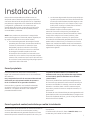
Power Decrease at High Altitude or
High Temperature
Air density is less at high altitudes, resulting in less available
engine power. Specifically, engine power will decrease 3.5%
for each 1,000 feet (300 meters) above sea level and 1%
for each 10° F (5.6°C) above 77°F (25°C). Make sure you and
your installer consider these factors when determining total
generator load.
gaseous fuel supply increases, and the number of 90 degree
bends in the fuel supply increases; compensations in piping
and wiring materials must be made. This is necessary to
comply with local codes and overcome electrical voltage
drops and gaseous fuel pressure drops.
The factors mentioned above will have a direct affect on
the overall price of your generator installation.
In some areas you may need to acquire electrical permits for
installing the home generator, building permits for installing
gas lines, and permits for noise allowances. Your installer
should check your local codes AND obtain the permits before
installing the system.
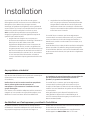
This section provides generator owners with the information
necessary to achieve the most satisfactory and cost effective
installation possible.
The illustrations are for typical circumstances and are meant
to familiarize you with the installation options available
with your generator. A thorough understanding of these
options will provide fundamental control over the cost of
your installation, as well as ensure your final satisfaction
and security.
Federal and local codes, appearance, noise levels, fuel types,
and distances are the factors that must be considered when
negotiating with an installation professional. Remember
that as the distance from the existing electrical service and
Owner Orientation

9
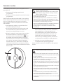
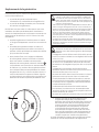
The actual physical location of your home generator has a
direct affect on:
1. The amount of plumbing required to fuel
your generator.
2. The amount of wiring required to control and connect
your generator.
Specific location guidelines are discussed in the installation
manual. Acquaint yourself with that information and confer
with your installer. Be sure to ask how your site might
affect installation costs and compliance with local codes
and standards.
• Install generator outdoors in an area that will not
accumulate deadly exhaust gas.
• DO NOT install generator where exhaust gas could
accumulate and enter inside or be drawn into a
potentially occupied building or structure.
• By law it is required in many states to have a Carbon
Monoxide (CO) detector in operating condition in
your home. Carbon monoxide detector(s)
A
MUST
be installed and maintained indoors according to
the manufacturer’s instructions/ recommendations.
A CO monitor is an electronic device that detects
hazardous levels of CO. When there is a buildup of
CO, the monitor will alert the occupants by flashing
visual indicator light and alarm. Smoke alarms cannot
detect CO gas.
Generator Location
WARNING Exhaust heat/gases could ignite combustibles or
structures resulting in death or serious injury.
• Exhaust outlet side of weatherproof enclosure must have at least
5 ft (1.5 m) minimum clearance from any structure, shrubs, trees or
any kind of vegetation.
• Standby generator weatherproof enclosure must be at least
5 ft (1.5 m) from windows, doors, any wall opening, shrubs or
vegetation over 12 inches (30.5 cm) in height.
• Standby generator weatherproof enclosure must have a minimum
of 5 ft (1.5 m) overhead clearance from any structure, overhang or
trees.
• DO NOT place weatherproof enclosure under a deck or other type
of structure that may confine airflow.
• USE ONLY flexible steel fuel line provided. Connect provided fuel
line to generator, DO NOT use with or substitute any other flexible
fuel line.
• Smoke detector(s) MUST be installed and maintained indoors
according to the manufacturer’s instructions/ recommendations.
Carbon monoxide alarms cannot detect smoke.
• DO NOT place weatherproof enclosure in manner other than shown
in illustrations.
WARNING Running engine gives off carbon monoxide, an
odorless, colorless, poison gas.
Breathing carbon monoxide could result in death, serious
injury, headache, fatigue, dizziness, vomiting, confusion,
seizures, nausea or fainting.
• Operate this product ONLY outdoors in an area that will not
accumulate deadly exhaust gas.
• Keep exhaust gas away from any windows, doors, ventilation
intakes, soffit vents, crawl spaces, open garage doors or other
openings that can allow exhaust gas to enter inside or be drawn
into a potentially occupied building or structure.
• Carbon monoxide detector(s) MUST be installed and maintained
indoors according to the manufacturer’s instructions/
recommendations. Smoke alarms cannot detect carbon
monoxide gas.
• Ensure exhaust gas is kept away from any windows,
doors, ventilation intakes, soffit vents, crawl spaces,
open garage doors or other openings that can
allow exhaust gas to enter inside or be drawn into
a potentially occupied building or structure. Your
neighbor(s) home may be exposed to the engine
exhaust from your standby generator and must be
considered when installing your standby generator.
• Wind and air currents should be taken into
consideration when positioning generator.
See the installation manual for full details on safe generator
location.
A

10
Carefully inspect the home generator for any damage that
may have occurred during shipment.
If loss or damage is noted at time of delivery, have the
person(s) making delivery note all damage on the freight bill
and affix his signature under the consignor’s memo of loss or
damage. If loss or damage is noted after delivery, separate
the damaged materials and contact the carrier and your
installer for claim procedures. Parts damaged in shipping are
not warranted.
The home generator system is supplied with:
• Oil (5W30 Synthetic)
• Flexible steel fuel line
• Installation and start-up manual
• Operator’s manual
• Spare access roof keys
• Spare 15 Amp ATO-type fuse
• Remote wireless monitor
• Antenna
Not included:
• Carbon monoxide detector(s)
• Smoke detector(s)
• Starting battery
• Connecting wire and conduit
• Fuel supply valves/plumbing
• Crane, lifting straps, chains or cables
• Two 60” lengths of 3/4” nominal minimum scheduled
40 steel pipe (NOT conduit)
• Torque screwdriver, 5 to 50 inch-pound range
• Voltage/frequency meter
• Two (2) AA batteries for remote wireless monitor
Delivery Inspection

11
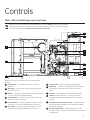
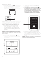
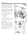
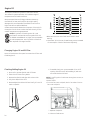
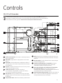
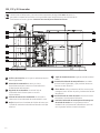
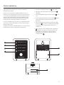
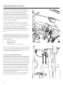
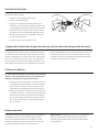
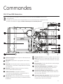
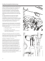
Read this operator’s manual and Important Safety Instructions before operating your generator.
Compare the illustration with your generator to familiarize yourself with the locations of various
controls and adjustments. Save this manual for future reference.
15kW, 17kW and 20kW Generator (Front View)
Generator is shown with roof and access covers removed
for clarity.
A
- Lifting Holes — Provided at each corner for lifting
generator.
B
- Alternator — An electrical machine that generates an
alternating current
C
- Muffler — High-performance muffler lowers engine noise
to comply with most residential codes.
D
- Circuit Breaker — Protects the system from shorts and
other over-current conditions.
E
- Control Board — Used for generator operation control,
menu start-up, and informational display functions.
F
- Air Cleaner — Uses a dry type filter element to protect
engine by filtering dust and debris out of intake air.
G
- Engine Label — Identifies engine model and type
H
- Spark Plug — A device in the cylinder head of the engine
that ignites the fuel mixture by means of an electric
spark.
J
- Oil Filter — Filters engine oil to prolong generator life.
K
- Battery (installer supplied) — 12 Volt DC, lead acid,
automotive style battery provides power to start the
engine.
L
- Oil Heater Port/ Oil Drain Hose Port — Provided to allow
an optional heating element to be installed. Provided to
facilitate oil changing.
M
- Generator Data Label — Identifies generator model
number and serial number. Located inside battery access
compartment.
Controls
B
A
C
D
E
F
G
H
J
K
L
M

12
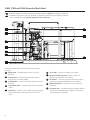
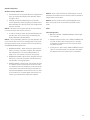
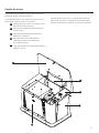
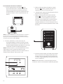
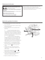
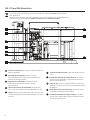
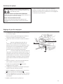
Read this operator’s manual and Important Safety Instructions before operating your generator.
Compare the illustration with your generator to familiarize yourself with the locations of various
controls and adjustments. Save this manual for future reference.
15kW, 17kW and 20kW Generator (Back View)
Generator is shown with roof and access covers removed
for clarity.
A
- Lifting Holes — Provided at each corner for lifting
generator.
B
- Fuel Solenoid — Automatically opens and closes to
supply fuel to unit when needed.
C
- Fuel Regulator — Controls fuel flow to engine for proper
operation.
D
- Fuel Selector Valve — Used to select proper fuel type (LP
or NG).
E
- Spark Plug — A device in the cylinder head of the engine
that ignites the fuel mixture by means of an electric
spark.
F
- Oil Fill Cap — Location for adding oil to engine.
G
- Electrical Field Wiring Inlet — Wires to and from
generator are centered in this location.
H
- Air Cleaner — Uses a dry type filter element to protect
engine by filtering dust and debris out of intake air.
J
- Engine Oil Dipstick — Allows user to check engine oil
level easily.
K
- Oil Heater Port — Provided to allow an optional heating
element to be installed to warm engine oil to promote
easy starting in cold climates.
A
B
C
D
E
F
G
H
J
K

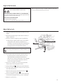
13
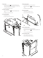
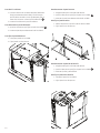
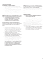
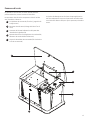
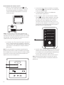
Each generator is shipped with a set of identical keys. These
keys fit in the lock on the front removable panel. The roof
must be unlocked in order for it to open.
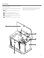
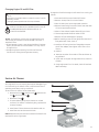
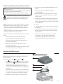
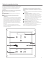
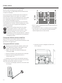
Access Panels
The generator is equipped with an enclosure that has several
access panels, as shown.
The access panels and the components located behind them
are listed below:
A - Roof (Control Panel, air filter, oil dipstick, and circuit
breaker)
B - Front Access Panel (oil drain and oil filter)
D - Battery Panel (battery and generator data label)
E - Rear Access Panel (fuel regulator, fuel selector switch,
and engine starter)
F - Control Panel Cover (field wiring and control wires)
B
A
A
B
B
C
C
D
E
D
E

14
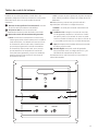
B
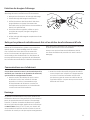
To open roof:
1. Insert key into lock of front panel. Gently push
down on roof above the lock to aid in turning the key.
Turn key one quarter turn clockwise.
2. Lift roof to the open position.
To remove front panel:
1. Remove the two bolts that secure the panel to the
unit.
2. Lift panel to remove from unit.
To secure front panel:
1. Place panel in unit.
2. Secure the panel with two bolts.
To remove rear panel:
1. Ensure the roof is in the open position.
2. Remove the two bolts that secure the panel to the
unit.
3. Lift panel to remove from unit.
To secure rear panel:
1. Slide panel into place on unit.
2. Secure the panel with two bolts.
To remove battery panel:
1. Ensure the roof is in the open position.
2. Remove the two bolts that secure the panel to the
unit.
3. Lift up on panel and remove.
To secure battery panel:
1. Place panel into place in unit.
2. Secure the panel with two bolts.
A
B
C
D
A
B
C
D

15
ok
menu
esc
auto
off manual
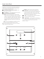
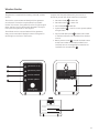
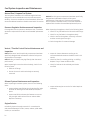
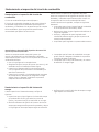
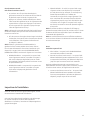
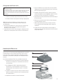
System Control Panel
The generator control board, located inside the generator,
under the roof, is shown below. Brief descriptions of the
controls used during installation are:
A
- Menu/Programming Navigation Buttons — See
Menu section for details
B
- Mini USB Port — Authorized Dealer Service Use Only.
C
- Generator Operation Control Buttons —
•“AUTO” Normal operating position. Press and hold
button to put unit into Automatic mode. In Automatic
mode, if a utility power outage is sensed, the system
will start the generator. When utility power is restored,
auto lets the engine stabilize internal temperatures,
shuts o the generator, and waits for the next utility
outage.
•“OFF” Turns o running generator, prevents unit from
starting, and resets any detected service codes.
OFF must be pressed and held for more than 5 seconds in
order to reset service code memory.
•“MANUAL” Used to manually start the generator.
D
– 15 Amp Fuse — Protects the home generator DC
control circuits. If the fuse has ‘blown’ (melted open)
or was removed, the engine cannot crank or start.
Replace the fuse using only an identical ATO 15A fuse.
One spare fuse is supplied with the unit.
E
- Cover — This protective cover must be removed to
access the fuse and the USB port.
F
- Digital Display — Displays generator mode, menu
options, service codes, and service engine indicators
More information may be found in Controls in the
operator’s manual.
A
B
C
D
F
E

16
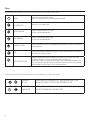
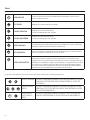
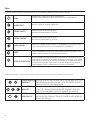
Menu
MENU
ENTER THE MENU (VIEW SETTINGS)
PRESS TO CONFIRM SELECTION WHEN PROGRAMMING.
ESCAPE (EXIT)
RETURN TO LAST MENU ITEM
RIGHT ARROW
TOGGLE THROUGH MENU OPTIONS
SETTING SYSTEM PARAMETERS
LEFT ARROW
TOGGLE THROUGH MENU OPTIONS
SETTING SYSTEM PARAMETERS
MANUAL MODE
USED TO MANUALLY START THE GENERATOR. PRESS AND HOLD BUTTON TO START
THE GENERATOR.
OFF
TURNS OFF RUNNING GENERATOR, PREVENTS UNIT FROM STARTING, AND RESETS
ANY DETECTED SERVICE CODES
AUTOMATIC MODE
NORMAL OPERATING POSITION. PRESS AND HOLD BUTTON TO PUT UNIT INTO
AUTOMATIC MODE. IF A UTILITY POWER OUTAGE IS SENSED, THE
SYSTEM WILL START THE GENERATOR. WHEN UTILITY POWER IS RESTORED, AUTO
LETS THE ENGINE STABILIZE INTERNAL TEMPERATURES, SHUTS OFF THE GENERA-
TOR, AND WAITS FOR THE NEXT UTILITY POWER OUTAGE.
ok
ok
ok
ok
ok
ok
ok
GENERAL
SET-UP
PRESS AND HOLD [ARROW LEFT AND ARROW RIGHT] FOR
THREE SECONDS TO ENTER THE PROGRAM MODE.
WIRELESS
LINK MODE
PRESS AND HOLD [MENU AND ESC] FOR THREE SECONDS TO
ENTER THE WIRELESS LINKING MODE.
The following chart shows the icons for the buttons that control the system control panel.
The following chart describes key sequences for accessing different programming modes;
ok
ok
ok
ok

17
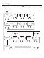
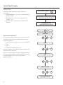
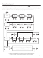
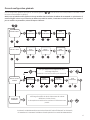
General Set Up Screen
For general set up, press and hold the left arrow and right arrow for 3 seconds. Follow the prompts as outlined below.
NOTE: Date and Time were set at the factory and stored in the control panel memory. The Exercise Cycle was also set at
the factory. The default exercise cycle occurs on Tuesdays, at 2:00 P.M. Central Standard Time. To update or change these
settings, follow the steps below.
ok
ok
SET DATE
If set to OFF, display will read:
EXERCISE CYCLE OFF
or
YEAR
FLASHING
MONTH
FLASHING
DAY##
FLASHING
SET TIME
HOURS
FLASHING
MINUTES
FLASHING
AM/PM
FLASHING
or or or
or
or or or
or
or
or or or or
DAY OF WEEK
FLASHING
HOURS
FLASHING
MINUTES
FLASHING
AM/PM
FLASHING
SET EXERCISE
CYCLE
EVENT LOG
Display will scroll last service code event, date, time,
and ambient temperature of when the event occurred.
or
IF DURING PROGRAMMING NO BUTTONS ARE PRESSED FOR 30 SECONDS,
THE CONTROL PANEL WILL AUTOMATICALLY EXIT THE PROGRAM MODE.

18
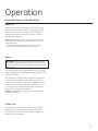
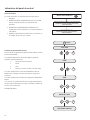
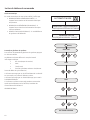
Control Panel Prompts
Automatic Mode
In Automatic Mode, the display screen will display via
scrolling text:
• GENERATOR READY - if the unit is in standby and utility
power is present.
• GENERATOR ON - if the unit is running and utility
power is not on.
• SERVICE CODE - if a system service code has been
detected.
General System Parameters
To view general system parameters, press the MENU button.
The following will scroll across the digital display and then
move to the next item:
• Run time (total hours the unit has run since installation)
• Date
• Time
• Exercise Cycle date and start time
The user can press the LEFT ARROW or RIGHT ARROW at any
time to move to the next item.
The user can press ESCAPE to go back to GENERATOR READY.
If no user inputs are made for 10 seconds after all the items
have been displayed, the control board will reset to
GENERATOR READY.
AUTOMATIC MODE
RUN TIME
DATE
or
or
or
TIME
EXERCISE CYCLE
SOFTWARE VERSION
GENERATOR ON
(When Generator Running - Auto Mode)
GENERATOR READY or SERVICE CODE DESCRIPTION
(When Generator NOT Running - Auto Mode)
(MENU)
ok
or
ok
or
ok
or
ok
or
or
ok
AUTOMATIC MODE
RUN TIME
DATE
or
or
or
TIME
EXERCISE CYCLE
SOFTWARE VERSION
GENERATOR ON
(When Generator Running - Auto Mode)
GENERATOR READY or SERVICE CODE DESCRIPTION
(When Generator NOT Running - Auto Mode)
(MENU)
ok
or
ok
or
ok
or
ok
or
or
ok

19
Operation
Battery
The installer must supply a rechargeable 12 volt DC starting
battery. See Battery in Final Installation Considerations in the
installation manual.
With the battery installed, all wiring to transfer switch and
home generator completed, utility power supplied to the
automatic transfer switch, and the unit in AUTO mode, the
battery receives a trickle charge while the engine is not
running. The trickle charge cannot be used to recharge a
battery that is completely discharged.
NOTICE A battery booster should never be used to quick
charge a low battery.
Engine Oil
The engine is shipped from the factory pre-run and filled
with synthetic oil (API SJ/CF 5W-30). This allows for system
operation in a wide range of temperature and climate
conditions. Before starting the engine, check oil level as
described in Maintenance.
Important Owner’s Considerations
NOTICE Any attempt to crank or start the engine before it has
been properly serviced with the recommended oil will result in
equipment failure.
• Damage to equipment resulting from failure to follow this
instruction will void engine and generator warranty.
WARNING Battery posts, terminals and related accessories
contain lead and lead compounds, chemicals known to the State
of California to cause cancer and reproductive harm. Wash hands
after handling.
15 Amp Fuse
The generator’s 15 Amp fuse is critical to correct system
operation. The 15 Amp fuse was removed at the factory.
Your installer will ensure the fuse is properly installed upon
completion of the installation.

20
The generator is equipped with an exercise timer. During the
exercise period, the unit runs for approximately 20 minutes
and then shuts down. Electrical load transfer DOES NOT
occur during the exercise cycle (unless an utility power
outage occurs).
The generator will only enter the exercise cycle if the unit
is in the AUTO mode and this exact procedure is followed.
To set the exercise timer:
NOTICE The generator is set with a deservice code exercise
cycle setting of Tuesday at 2:00 P.M, Central Time. To change
the cycle setting, proceed to the following steps:
1. Choose the day and time you want your generator to
exercise.
2. Press and hold the left arrow and right arrow
simultaneously for three seconds to enter the General
Set-Up program mode. See General Set-Up flow chart
in Menu Section.
3. Verify and/or set the time and date on the unit.
4. Go to the SET EXERCISE prompt and hit the “OK”
button.
NOTICE Items will flash until they are selected.
Setting Exercise Timer
SELECT DAY: Use the left or right arrow to toggle
through the days of the week, Once the day is
selected, hit the “OK” button.
SELECT HOUR: Use the left or right arrow to toggle
through between 1 and 12. Choose the hour of day
you want the generator to exercise then hit the “OK”
button.
SELECT MINUTE: Use the left of right arrow to toggle
between :00 and :59. Choose the minute of the day
you want the generator to exercise then hit the “OK”
button.
SELECT AM/PM: Use the left of right arrow to toggle
between AM and PM. Once chosen, hit the “OK”
button.
NOTICE During the weekly exercise cycle, the generator will
run for 20 minutes, but it will not supply power to the home.
During the exercise cycle, the in-home monitor will continue
blinking the GENERATOR READY green LED.
If you want to change the day and time the unit exercises,
simply perform the procedure again.
To turn off the generator exercise cycle, go to the OFF
selection within the day of the week menu and press OK. The
display will then scroll: EXERCISE CYCLE OFF.
Automatic Operation
The generator’s control board constantly monitors utility
voltage. Should utility voltage drop below a preset level, the
control board will signal the engine to crank and start.
When utility voltage is restored above a preset voltage level,
the engine is signaled to shut down.
The actual system operation is not adjustable and is
sequenced by sensors and timers on the control board,
as follows:
Utility Voltage Dropout Sensor
• This sensor monitors utility source voltage.
• If utility source voltage drops below about 70 percent
of the nominal supply voltage, the sensor energizes
a 3 second timer. The timer is used to ‘sense’
brown-outs.
• Once the timer has expired, the engine will crank
and start.
Utility Voltage Pickup Sensor
This sensor monitors utility voltage. When utility voltage is
restored above 80 percent of the nominal source voltage,
a time delay starts timing and the engine will go to engine
cool-down.
Engine Cool-down Timer
When utility power is sensed and the load transfers back to
the utility source, the engine will go into a cool down period
as described below:
• If the generator has run for MORE than 5 minutes,
once the utility transfer occurs, the engine will
continue to run for about 1 minute before shutting
down.
• If the generator has run for LESS than 5 minutes, once
the utility transfer occurs, the engine will continue to
run until 5 minutes has elapsed before shutting down.
La page charge ...
La page charge ...
La page charge ...
La page charge ...
La page charge ...
La page charge ...
La page charge ...
La page charge ...
La page charge ...
La page charge ...
La page charge ...
La page charge ...
La page charge ...
La page charge ...
La page charge ...
La page charge ...
La page charge ...
La page charge ...
La page charge ...
La page charge ...
La page charge ...
La page charge ...
La page charge ...
La page charge ...
La page charge ...
La page charge ...
La page charge ...
La page charge ...
La page charge ...
La page charge ...
La page charge ...
La page charge ...
La page charge ...
La page charge ...
La page charge ...
La page charge ...
La page charge ...
La page charge ...
La page charge ...
La page charge ...
La page charge ...
La page charge ...
La page charge ...
La page charge ...
La page charge ...
La page charge ...
La page charge ...
La page charge ...
La page charge ...
La page charge ...
La page charge ...
La page charge ...
La page charge ...
La page charge ...
La page charge ...
La page charge ...
La page charge ...
La page charge ...
La page charge ...
La page charge ...
La page charge ...
La page charge ...
La page charge ...
La page charge ...
La page charge ...
La page charge ...
La page charge ...
La page charge ...
La page charge ...
La page charge ...
La page charge ...
La page charge ...
La page charge ...
La page charge ...
La page charge ...
La page charge ...
La page charge ...
La page charge ...
La page charge ...
La page charge ...
La page charge ...
La page charge ...
La page charge ...
La page charge ...
La page charge ...
La page charge ...
La page charge ...
La page charge ...
La page charge ...
La page charge ...
La page charge ...
La page charge ...
La page charge ...
La page charge ...
La page charge ...
La page charge ...
La page charge ...
La page charge ...
La page charge ...
La page charge ...
-
 1
1
-
 2
2
-
 3
3
-
 4
4
-
 5
5
-
 6
6
-
 7
7
-
 8
8
-
 9
9
-
 10
10
-
 11
11
-
 12
12
-
 13
13
-
 14
14
-
 15
15
-
 16
16
-
 17
17
-
 18
18
-
 19
19
-
 20
20
-
 21
21
-
 22
22
-
 23
23
-
 24
24
-
 25
25
-
 26
26
-
 27
27
-
 28
28
-
 29
29
-
 30
30
-
 31
31
-
 32
32
-
 33
33
-
 34
34
-
 35
35
-
 36
36
-
 37
37
-
 38
38
-
 39
39
-
 40
40
-
 41
41
-
 42
42
-
 43
43
-
 44
44
-
 45
45
-
 46
46
-
 47
47
-
 48
48
-
 49
49
-
 50
50
-
 51
51
-
 52
52
-
 53
53
-
 54
54
-
 55
55
-
 56
56
-
 57
57
-
 58
58
-
 59
59
-
 60
60
-
 61
61
-
 62
62
-
 63
63
-
 64
64
-
 65
65
-
 66
66
-
 67
67
-
 68
68
-
 69
69
-
 70
70
-
 71
71
-
 72
72
-
 73
73
-
 74
74
-
 75
75
-
 76
76
-
 77
77
-
 78
78
-
 79
79
-
 80
80
-
 81
81
-
 82
82
-
 83
83
-
 84
84
-
 85
85
-
 86
86
-
 87
87
-
 88
88
-
 89
89
-
 90
90
-
 91
91
-
 92
92
-
 93
93
-
 94
94
-
 95
95
-
 96
96
-
 97
97
-
 98
98
-
 99
99
-
 100
100
-
 101
101
-
 102
102
-
 103
103
-
 104
104
-
 105
105
-
 106
106
-
 107
107
-
 108
108
-
 109
109
-
 110
110
-
 111
111
-
 112
112
-
 113
113
-
 114
114
-
 115
115
-
 116
116
-
 117
117
-
 118
118
-
 119
119
-
 120
120


Simplicity 040378-02 Manuel utilisateur
- Catégorie
- Groupes électrogènes
- Taper
- Manuel utilisateur
dans d''autres langues
- English: Simplicity 040378-02 User manual
- español: Simplicity 040378-02 Manual de usuario