
101647_RevH 09/21
www.KaliaStyle.com
Conserver ce guide après l’installation car il contient des informations utiles
pour le service et la garantie.
Keep these instructions after you have nished the installation, it contains useful
information regarding service and warranty.
Numéro de série/Serial number
101559
Valve thermostatique ½’’
½’’ Thermostatic Valve
101567
Valve thermostatique ¾’’
¾’’ Thermostatic Valve
Instructions d’installation - Garantie
Installation Instructions - Warranty

2
101647_RevH
Merci d’avoir choisi un produit Kalia et de faire
conance à notre entreprise.
Kalia a une philosophie d’affaires basée sur
des valeurs fondamentales dont l’innovation et
l’excellence ainsi qu’un service personnalisé
adapté aux exigences d’aujourd’hui et de demain.
Nous sommes convaincus que ce produit saura
vous plaire et surpassera vos exigences en termes
de abilité et durabilité. Nous sommes là pour
vous!
Dans ce guide vous trouverez toute l’information
nécessaire à l’installation et au bon fonctionnement
de votre produit Kalia.
Dans le but d’assurer une installation et une
utilisation optimales veuillez prendre quelques
minutes pour étudier ce guide.
En cas de problème d’installation ou de perfor-
mance, veuillez communiquer avec nous au numéro
sans frais 1 877 GO KALIA (1-877-465-2542)
ou par courriel au [email protected].
Nous vous remercions encore une fois d’avoir
choisi un produit Kalia.
Merci d’avoir choisi Kalia !
Thank you for choosing a Kalia product and for
placing your trust in our company.
The Kalia business philosophy is based on a solid
core of values focused on providing innovation
and excellence as well as a personalized service
designed to meet the changing needs of today
and tomorrow.
We are convinced that you will be fully satised
with your new Kalia product and that it will
exceed your expectations in terms of reliability
and durability. At Kalia we put our expertise to
work for you!
This guide contains all the necessary information
for the installation and proper use of your Kalia
product. To ensure the smooth installation and
optimal use of your product, we recommend
taking a few moments to study the information
provided in this guide.
In the event that you should encounter a problem
related to the installation or the performance of
this product, please contact us at our toll-free
line 1 877 GO KALIA (1-877-465-2542) or by
email at: s[email protected].
Thank you once again for choosing Kalia.
Thank you for choosing Kalia!

3
101647_RevH
Renseignements importants
IMPORTANT
- Lire attentivement le présent guide avant
l’installation.
- Assurez-vous d’avoir tous les outils et
matériaux nécessaires à l’installation.
- Vérier que toutes les pièces illustrées à la
section Schéma des pièces sont incluses et
qu’aucune pièce n’est endommagée. Si un
problème survient, le signaler immédiatement
au vendeur.
- Respecter tous les codes de plomberie et de
bâtiment locaux.
Kalia se réserve le droit d’apporter toute
modication au design du produit et ceci sans
préavis. Utiliser le manuel d’installation fourni
dans l’emballage.
Kalia n’est pas responsable des problèmes causés
par une installation non conforme aux directives
énoncées dans le présent guide.
Bonne installation !
Important Information
IMPORTANT
- Read this guide before proceeding with the
installation.
- Make sure you have all the tools and materials
needed for installation.
- Make sure all the parts shown in the Parts
Diagram section are included and in good
condition. If there is a problem, report it
immediately to the seller.
- Respect all local plumbing and building
codes.
Kalia reserves the right to make any changes to
the design of the product, without notice. Use the
installation instruction supplied with the product.
Kalia is not responsible for problems caused by
an installation not executed in accordance with
the directions given in this guide.
Thank you!

4
101647_RevH
Instruction Part list_Shower Faucets
*
Valve Thermo 101559 *
#
Numéro de pièce
Part Number
Description
Qté totale
Total qty
1 101550 Vis 10-24, 1 5/32" / Screw 10-24, 1 5/32" 2
2 101337 Gabarit de plastique / Plastic template 1
3 - Écrou de cartouche / Cartridge nut 1
4 Vis M4-7x13mm / Screw M4-7x13mm 1
5 Pignon denté / Stem adaptor 1
6 Cartouche / Cartridge 1
7 101726 Valve d'arrêt / Shut-off valve 2
8 102112 Vis de serrage M4x7mm / Screw M4x7mm 1
9 - Corps de la valve / Valve body 1
10 101769 Bouchon de sortie / Outlet cap 1
101757
[ S:\1.KALIA\1._R&D\5.Guides_d'installation\2. Robinetterie de salle de bain\2. Robinetterie de douche\Instruction Part list_Shower Faucets ]
1
2
3
8
4
5
6
7
10
9
Schéma des pièces Parts Diagram
VALVE THERMOSTATIQUE
½
’’ /
½’’
THERMOSTATIC VALVE
101559
Liste des pièces Parts List

5
101647_RevH
Instruction Part list_Shower Faucets.xlsx
*Valve Thermo 101567 *
#Numéro de pièce
Part Number Description Qté totale
Total qty
1 101842 Vis 10-24, 3 13/16'' / Screw 10-24, 3 13/16'' 2
2 Gabarit de plastique / Plastic template 1
3 Espaceur / Spacer 2
4 - Écrou de cartouche / Cartridge nut 1
5 Vis M4-7x13mm / Screw M4-7x13mm 1
6 Pignon denté / Stem adaptor 1
7 Cartouche / Cartridge 1
8 101844 Valve d'arrêt rouge / Red shut-off valve 1
9 102019 Valve d'arrêt bleue / Blue shut-off valve 1
10 - Corps de la valve / Valve body 1
11 101840 Bouchon de sortie / Outlet cap 1
101841
101843
[
S:\1.KALIA\1.
_
R&D\5.Guides
_
d'installation\2. Robinetterie de salle de bain\2. Robinetterie de douche\Instruction Part list
_
Shower
Faucets.xlsx ]
2
1
3
4
5
67
8
9
11
10
Schéma des pièces Parts Diagram
VALVE THERMOSTATIQUE
¾
’’ /
¾’’
THERMOSTATIC VALVE
101567
Liste des pièces Parts List

6
101647_RevH
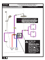
Chaud
Hot
Froid
Cold
Sore du haut (2e composante oponnel)
bouchée avec le capuchon inclus
Top oulet (2nd oponal component)
blocked with the included cap
POUR UNE INSTALLATION À 2 VALVES, VOIR AU VERSO DE LA FEUILLE. / FOR 2 VALVES INSTALLATION SEE BACK OF SHEET.
* Note: Ce système de douche est présenté à titre indicatif seulement./This shower system is present at the title number only.
ATTENTION
Soyez prudent,
plusieurs erreurs lors de
l’installation de la nition
peuvent se produire.
Important de se référer au
guide d’installation./
Be careful, several errors
during installation of the
decorative trim may occur.
Important to refer to the
installation guide.
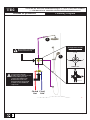
T1
Système de douche thermostatique 1/2’’
1/2’’ Thermostatic Shower System
Plumbing DiagramSchéma de plomberie
01/20 102322_T1_RevA
1355, 2e Rue, Parc industriel
Sainte-Marie (Québec)
Canada G6E 1G9
T 418 387-9090
1 877 GO-KALIA (1 877 465-2542)
F 418 387-9089
KaliaStyle.com
102322
Schéma de plomberie Plumbing Diagram
SYSTÈME DE DOUCHE THERMOSTATIQUE ½’’
½’’ THERMOSTATIC SHOWER SYSTEM
T1

7
101647_RevH
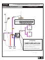
Chaud
Hot
Froid
Cold
Sore du haut (2e composante oponnel)
bouchée avec le capuchon inclus
Top oulet (2nd oponal component)
blocked with the included cap
POUR UNE INSTALLATION À 2 VALVES, VOIR AU VERSO DE LA FEUILLE. / FOR 2 VALVES INSTALLATION SEE BACK OF SHEET.
* Note: Ce système de douche est présenté à titre indicatif seulement./This shower system is present at the title number only.
ATTENTION
Soyez prudent,
plusieurs erreurs lors de
l’installation de la nition
peuvent se produire.
Important de se référer au
guide d’installation./
Be careful, several errors
during installation of the
decorative trim may occur.
Important to refer to the
installation guide.
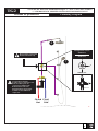
T1
Système de douche thermostatique 1/2’’ (1 valve de contôle de volume)
1/2’’ Thermostatic Shower System (1 volume control valve)
Plumbing DiagramSchéma de plomberie
01/20 104210_T1_1volume-control_RevA
1355, 2e Rue, Parc industriel
Sainte-Marie (Québec)
Canada G6E 1G9
T 418 387-9090
1 877 GO-KALIA (1 877 465-2542)
F 418 387-9089
KaliaStyle.com
104210
Schéma de plomberie Plumbing Diagram
SYSTÈME DE DOUCHE THERMOSTATIQUE ½’’ (1 VALVE DE CONTRÔLE DE VOLUME)
½’’ THERMOSTATIC SHOWER SYSTEM (1 VOLUME CONTROL VALVE)
T1

8
101647_RevH
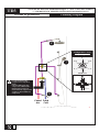
Schéma de plomberie Plumbing Diagram
SYSTÈME DE DOUCHE THERMOSTATIQUE ½’’
½’’ THERMOSTATIC SHOWER SYSTEM
T2
Chaud
Hot
Froid
Cold
ATTENTION
Soyez prudent,
plusieurs erreurs lors de
l’installation de la nition
peuvent se produire.
Important de se référer au
guide d’installation./
Be careful, several errors
during installation of the
decorative trim may occur.
Important to refer to the
installation guide.
T2
Système de douche thermostatique 1/2”
Thermostatic shower system 1/2”
Plumbing DiagramSchéma de plomberie
POUR UNE INSTALLATION À 2 VALVES, VOIR AU VERSO DE LA FEUILLE. / FOR 2 VALVES INSTALLATION SEE BACK OF SHEET.
* Note: Ce système de douche est présenté à titre indicatif seulement./This shower system is present at the title number only.
01/20 102324 (T2 90° wallarm)_RevB
1355, 2e Rue, Parc industriel
Sainte-Marie (Québec)
Canada G6E 1G9
T 418 387-9090
1 877 GO-KALIA (1 877 465-2542)
F 418 387-9089
KaliaStyle.com
102324

9
101647_RevH
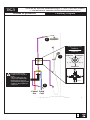
Schéma de plomberie Plumbing Diagram
SYSTÈME DE DOUCHE THERMOSTATIQUE ½’’ (2 VALVES DE CONTRÔLE DE VOLUME)
½’’ THERMOSTATIC SHOWER SYSTEM (2 VOLUME CONTROL VALVES)
T2
Chaud
Hot
Froid
Cold
T2
Système de douche thermostatique 1/2’’ (2 valves de contrôle de volume)
1/2’’ Thermostatic Shower System (2 volume control valves)
Plumbing DiagramSchéma de plomberie
POUR UNE INSTALLATION À 2 VALVES, VOIR AU VERSO DE LA FEUILLE. / FOR 2 VALVES INSTALLATION SEE BACK OF SHEET.
* Note: Ce système de douche est présenté à titre indicatif seulement./This shower system is present at the title number only.
01/20 104209_T2_2-volume-control_RevA
1355, 2e Rue, Parc industriel
Sainte-Marie (Québec)
Canada G6E 1G9
T 418 387-9090
1 877 GO-KALIA (1 877 465-2542)
F 418 387-9089
KaliaStyle.com
104209
ATTENTION
Soyez prudent,
plusieurs erreurs lors de
l’installation de la nition
peuvent se produire.
Important de se référer au
guide d’installation./
Be careful, several errors
during installation of the
decorative trim may occur.
Important to refer to the
installation guide.

10
101647_RevH
Schéma de plomberie Plumbing Diagram
SYSTÈME DE DOUCHE THERMOSTATIQUE ½’’ AVEC VALVE DÉVIATRICE
½’’ THERMOSTATIC SHOWER SYSTEM WITH DIVERTER VALVE
TD2
La sortie du bas doit être
bouchée avec le capuchon inclus.
Peut être utilisé pour une
composante additionnelle.
Bottom outlet needs to be
blocked with the cap provided.
Could be used for additional
component.
Chaud
Hot
Froid
Cold
2
1
Ne pas retirer ce bouchon
Do not remove this cap
POUR UNE INSTALLATION À 2 VALVES, VOIR AU VERSO DE LA FEUILLE. / FOR 2 VALVES INSTALLATION SEE BACK OF SHEET.
TD2
Système de douche thermostatique 1/2”
Thermostatic shower system 1/2”
12/19 104331_TD2_RevA
FERMÉ / OFF
1 + 2
1
2
3 1
2
Conguration 2 voies
2-way conguration
IN
ENTRÉE/INLET
1
2
* Note: Ce système de douche est présenté à titre indicatif seulement./This shower system is present at the title number only.
Plumbing DiagramSchéma de plomberie
104331
1355, 2e Rue, Parc industriel
Sainte-Marie (Québec)
Canada G6E 1G9
T 418 387-9090
1 877 GO-KALIA (1 877 465-2542)
F 418 387-9089
KaliaStyle.com

11
101647_RevH
Schéma de plomberie Plumbing Diagram
SYSTÈME DE DOUCHE THERMOSTATIQUE ½’’ AVEC VALVE DÉVIATRICE
½’’ THERMOSTATIC SHOWER SYSTEM WITH DIVERTER VALVE
TG2
La sortie du bas doit être
bouchée avec le capuchon inclus.
Peut être utilisé pour une
composante additionnelle.
Bottom outlet needs to be
blocked with the cap provided.
Could be used for additional
component.
Chaud
Hot
Froid
Cold
2
1
Ne pas retirer ce bouchon
Do not remove this cap
POUR UNE INSTALLATION À 2 VALVES, VOIR AU VERSO DE LA FEUILLE. / FOR 2 VALVES INSTALLATION SEE BACK OF SHEET.
TG2
Système de douche thermostatique 1/2” CalGreen
CalGreen thermostatic shower system 1/2”
FERMÉ / OFF
2
1
2
3 1
2
IN
ENTRÉE/INLET
1
Conguration 2 voies
(CalGreen)
2-way conguration
(CalGreen)
* Note: Ce système de douche est présenté à titre indicatif seulement./This shower system is present at the title number only.
Plumbing DiagramSchéma de plomberie
01/20 104304_TG2_RevA
1355, 2e Rue, Parc industriel
Sainte-Marie (Québec)
Canada G6E 1G9
T 418 387-9090
1 877 GO-KALIA (1 877 465-2542)
F 418 387-9089
KaliaStyle.com
104304

12
101647_RevH
Schéma de plomberie Plumbing Diagram
SYSTÈME DE DOUCHE THERMOSTATIQUE ½’’ AVEC VALVE DÉVIATRICE
½’’ THERMOSTATIC SHOWER SYSTEM WITH DIVERTER VALVE
TD3
La sortie du bas doit être
bouchée avec le capuchon
inclus.
Peut être utilisé pour une
composante additionnelle.
Bottom outlet needs to be
blocked with the cap provided.
Could be used for additional
component.
Chaud
Hot
Froid
Cold
2
1
3
POUR UNE INSTALLATION À 2 VALVES, VOIR AU VERSO DE LA FEUILLE. / FOR 2 VALVES INSTALLATION SEE BACK OF SHEET.
TD3
Système de douche thermostatique 1/2”
Thermostatic shower system 1/2”
FERMÉ / OFF
1
1 + 32 + 1
32
1
3
2
3 1
2
Conguration 3 voies
3-way conguration
IN
ENTRÉE/INLET
* Note: Ce système de douche est présenté à titre indicatif seulement./This shower system is present at the title number only.
Plumbing DiagramSchéma de plomberie
01/20 104333_TD3_RevA
1355, 2e Rue, Parc industriel
Sainte-Marie (Québec)
Canada G6E 1G9
T 418 387-9090
1 877 GO-KALIA (1 877 465-2542)
F 418 387-9089
KaliaStyle.com
104333

13
101647_RevH
Schéma de plomberie Plumbing Diagram
SYSTÈME DE DOUCHE THERMOSTATIQUE ½’’ AVEC VALVE DÉVIATRICE
½’’ THERMOSTATIC SHOWER SYSTEM WITH DIVERTER VALVE
TG3
La sortie du bas doit être
bouchée avec le capuchon
inclus.
Peut être utilisé pour une
composante additionnelle.
Bottom outlet needs to be
blocked with the cap provided.
Could be used for additional
component.
Chaud
Hot
Froid
Cold
2
1
3
POUR UNE INSTALLATION À 2 VALVES, VOIR AU VERSO DE LA FEUILLE. / FOR 2 VALVES INSTALLATION SEE BACK OF SHEET.
TG3
Système de douche thermostatique 1/2” CalGreen
CalGreen thermostatic shower system 1/2”
FERMÉ / OFF
1
FERMÉ/OFFFERMÉ/OFF
32
1
3
2
3 1
2
IN
ENTRÉE/INLET
Conguration 3 voies
(CalGreen)
3-way conguration
(CalGreen)
* Note: Ce système de douche est présenté à titre indicatif seulement./This shower system is present at the title number only.
Plumbing DiagramSchéma de plomberie
01/20 104306_TG3_RevA
1355, 2e Rue, Parc industriel
Sainte-Marie (Québec)
Canada G6E 1G9
T 418 387-9090
1 877 GO-KALIA (1 877 465-2542)
F 418 387-9089
KaliaStyle.com
104306

14
101647_RevH
Schéma de plomberie Plumbing Diagram
SYSTÈME DE DOUCHE THERMOSTATIQUE 3/4’’
3/4’’ THERMOSTATIC SHOWER SYSTEM
T375
Chaud
Hot
Froid
Cold
T375
Système de douche thermostatique 3/4’’
3/4’’ Thermostatic Shower System
Plumbing DiagramSchéma de plomberie
POUR UNE INSTALLATION À 2 VALVES, VOIR AU VERSO DE LA FEUILLE. / FOR 2 VALVES INSTALLATION SEE BACK OF SHEET.
* Note: Ce système de douche est présenté à titre indicatif seulement./This shower system is present at the title number only.
01/20 102326_T375_90-wallarm_RevC
1355, 2e Rue, Parc industriel
Sainte-Marie (Québec)
Canada G6E 1G9
T 418 387-9090
1 877 GO-KALIA (1 877 465-2542)
F 418 387-9089
KaliaStyle.com
102326

15
101647_RevH
Schéma de plomberie Plumbing Diagram
SYSTÈME DE DOUCHE THERMOSTATIQUE 3/4’’ (3 VALVES DE CONTÔLE DE VOLUME)
3/4’’ THERMOSTATIC SHOWER SYSTEM (3 VOLUME CONTROL VALVES)
T375
T375
Système de douche thermostatique 3/4’’ (3 valves de contôle de volume)
3/4’’ Thermostatic Shower System (3 volume control valves)
Kalia inc.
1355, 2e Rue
Sainte-Marie (Québec)
Canada G6E 1G9
t. 1-418-387-9090
1 877 GO KALIA (1-877-465-2542)
f. 1-418-387-9089
www.KaliaStyle.com
11/19 104212_T375_90-wallarm-3volume-control_RevB
Schéma de plomberie Plumbing Diagram
Chaud
Hot
Froid
Cold
Une division égale de la tyuauterie
améliorera la performance des jets
ATTENTION
Soyez prudent, plusieurs erreurs lors de
Important de se référer au guide d’installation.
Be careful, several errors during installation of
the decorative trim may occur.
Important to refer to the installation guide.
POUR UNE INSTALLATION À 2 VALVES, VOIR AU VERSO DE LA FEUILLE / FOR 2 VALVES INSTALLATION SEE BACK OF SHEET

16
101647_RevH
Outils et matériaux nécessaires Necessary Tools and Materials
Perceuse électrique
Tournevis Phillips et plat
Crayon
Ruban à mesurer
Ruban d’étanchéité pour
letage
Clé à molette
Pince multiprise
Electric drill
Flat and Phillips
screwdriver
Pencil
Measuring tape
Thread sealant tape
Adjustable wrench
Gripping pliers
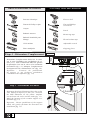
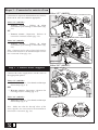
Étape 1 - Déterminer l’emplacement
Déterminer l’emplacement désiré de la valve
sur le mur. Identier une profondeur de 13
mm (1/2’’) entre l’indication MIN du gabarit
de plastique vissé sur la valve et les montants
d’ossatures (g. 1.1). Marquer l’emplacement
du support de bois minimum de 3/4’’(g. 1.2).
Important : S’assurer du parallélisme
du support ce qui facilitera grandement
l’installation de la nition (g. 1.2).
Fig. 1.1
13 mm (1/2’’)
Fig. 1.2
Step 1 - Determine Location
Determine the desired location of the valve on the
wall. Identify a depth of 13 mm (1/2’’) between
the MIN indication on the plastic template
screwed onto the valve and the studs (g. 1.1).
Mark the location of the wooden support 3/4’’
minimum (g. 1.2).
Important : Ensure parallelism of the support
which will greatly facilitate the decorative kit
installation (g. 1.2).

17
101647_RevH
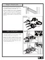
Step 2 - Fix the Valve
Fix a wooden board between the 2’’ x 4’’ studs
with angle bracket as per the depth chosen
previously to x the valve on it (g. 2.1).
Remove the plastic template off the valve.
Position the valve to put the mark UP towards
top then rmly x the valve on the wooden board
with screws as shown depending of the valve.
Put back the plastic template until the wall is
completely nished (g. 2.2).
Étape 2 - Fixer la valve
Fixer une planche de bois entre les montants 2’’ x
4’’ à l’aide d’équerre à la profondeur déterminée
sur laquelle sera xée la valve (g. 2.1).
Enlever le gabarit de la valve. Positionner
la valve de façon à ce que la marque UP soit
située vers le haut puis la xer solidement sur
la planche de bois à l’aide de vis aux endroits
illustrées selon le type de valve. Remettre le
gabarit en position jusqu’à la fermeture du mur
(g. 2.2).
Fig. 2.1
Va lve 1/2’’
101559
Va lve 3/4’’
101567
Va lve 1/2’’
101559
Fig. 2.2
Va lve 3/4’’
101567

18
101647_RevH
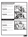
Step 3 - Connect Water Supplies
Connect the water supply hoses on the valve at
the appropriate places.
Valve 1/2’’ (101559) :
• Threaded version : Use thread sealant tape
if necessary (g. 3.1).
or
• Welded version : Important : Remove the
cartridge before welding (g. 3.2).
Valve 3/4’’ (101567) :
• Threaded version : Use thread sealant tape
if necessary (g. 3.3).
Note : Make sure that the shut-off valves of the
water supplies are unscrewed to the maximum to
avoid water restriction (g. 3.4).
Étape 3 - Connecter les entrées d’eau
Connecter les tuyaux d’alimentations aux entrées
d’eau sur la valve aux endroits appropriés.
Valve 1/2’’ (101559) :
• version fileTée : Utiliser du ruban
d’étanchéité pour letage si nécessaire (g.
3.1).
ou
• version soudée : Important : Enlever la
cartouche avant de souder (g. 3.2).
Valve 3/4’’ (101567) :
• version fileTée : Utiliser du ruban
d’étanchéité pour letage si nécessaire (g.
3.3).
Note : S’assurer que les valves d’arrêt des entrées
d’eau soient dévissées au maximum an d’éviter
une restriction d’eau (g. 3.4).
CHAUD
HOT
FROID
COLD
CHAUD
HOT FROID
COLD
Valve 1/2’’ (101559)
Version filetée / Threaded version
Version soudée / Welded version
Fig. 3.2
Fig. 3.1
CHAUD
HOT
FROID
COLD
Valve 3/4’’ (101567)
Fig. 3.3
101559 101567
Fig. 3.4

19
101647_RevH
Step 4 - Connect Water Outlets
Connect the water outlet(s) as per the components
used, the type of valve and the connection type
selected (g. 4.1).
Note : If only one outlet is used, make sure to
close the unused outlet with the included cap.
Valve 1/2’’ (101559) :
• Threaded version : Use thread sealant tape
if necessary (g. 4.1).
or
• Welded version : Important : Remove the
cartridge before welding (g. 4.2).
Valve 3/4’’ (101567) :
• Threaded version : Use thread sealant tape
if necessary (g. 4.3).
Étape 4 - Connecter les sorties d’eau
Connecter la ou les sortie(s) d’eau selon les
composantes utilisées, le type de valve et le type
de connection choisie.
Note : Si une seule sortie d’eau est utilisée,
s’assurer de fermer la sortie inutilisée avec le
bouchon inclus.
Valve 1/2’’ (101559) :
• version fileTée : Utiliser du ruban
d’étanchéité pour letage si nécessaire (g.
4.1).
ou
• version soudée : Important : Enlever la
cartouche avant de souder (g. 4.2).
Valve 3/4’’ (101567) :
• version fileTée : Utiliser du ruban
d’étanchéité pour letage si nécessaire (g.
4.3).
OU/OR
Valve 1/2’’ (101559)
Version filetée / Threaded version
Fig. 4.1
OU/OR
Version soudée / Welded version
Fig. 4.2
Valve 3/4’’ (101567)
OU/OR
Fig. 4.3

Étape 5 - Vérication
Il est important de valider que toutes les connections
fonctionnent correctement et qu’il n’y a pas de
fuites d’eau avant la fermeture du mur.
Votre installation est maintenant complétée !
Step 5 - Verication
It’s important to make sure that all the
connections are working properly to avoid water
leaking before closing the wall.
Your installation is now complete!
Garantie Warranty
GARANTIE À VIE LIMITÉE POUR LES SYSTÈMES DE
DOUCHE KALIA À L’EXCEPTION DES COMPOSANTES
SUIVANTES DONT LA GARANTIE EST POUR 1 AN :
• JeTs de corps
• TêTe de pluie
• pomme de douche
• doucheTTe
• Boyau flexiBle
• rail pour doucheTTe
• Bec de Bain mural
avec déviaTeur
Kalia inc. garantit à vie sa robinetterie de salle de bain
contre tout défaut de matériel ou de fabrication dans des
conditions normales d’utilisation et d’entretien tant et aussi
longtemps que l’acheteur/propriétaire possède sa résidence.
Pour information sur la garantie complète,
visitez le www.KaliaStyle.com.
LIFETIME LIMITED WARRANTY ON KALIA SHOWER
SYSTEMS EXCEPT 1 YEAR LIMITED WARRANTY FOR
THE FOLLOWING COMPONENTS :
• Body jets
• rainhead
• showerhead
• handshower
• FlexiBle hose
• wallBar
• tuB spout with
diverter
Kalia Inc. guarantees all aspects of its bathroom faucets
to be free of defects in material and workmanship for
normal residential use for as long as the original consumer/
purchaser owns his or her home.
For complete warranty information,
visit www.KaliaStyle.com.
Imprimé en Chine / Printed in China 101647_RevH
-
 1
1
-
 2
2
-
 3
3
-
 4
4
-
 5
5
-
 6
6
-
 7
7
-
 8
8
-
 9
9
-
 10
10
-
 11
11
-
 12
12
-
 13
13
-
 14
14
-
 15
15
-
 16
16
-
 17
17
-
 18
18
-
 19
19
-
 20
20


dans d''autres langues
- English: Kalia 101567 User guide
Documents connexes
-
Kalia BF1434-110-201 Guide de démarrage rapide
-
Kalia BF1179-120-200 Mode d'emploi
-
Kalia BF1249-120 Mode d'emploi
-
Kalia BF1493-110-001 Mode d'emploi
-
Kalia BF1648 Mode d'emploi
-
Kalia BF1708-110-101 Mode d'emploi
-
 Kalia BF1651 Mode d'emploi
-
 Kalia BF2067-001 Mode d'emploi
-
 Kalia BF1069 Guide d'installation
-
 Kalia BW1213-240 Mode d'emploi


