
W11183136A
W11183139A-SP
DRYER INSTALLATION INSTRUCTIONS
INSTRUCTIONS POUR L’INSTALLATION
DE LA SÉCHEUSE
INSTALLATION NOTES
Date of purchase: _________________________________
Date of installation: ________________________________
Installer: ________________________________________
Model number: ___________________________________
Serial number: ____________________________________
Date d’achat: _____________________________________
Date d’installation: ________________________________
Installateur: ______________________________________
Numéro de modéle: ________________________________
Numéro de série: __________________________________
NOTES CONCERNANT L’INSTALLATION
Para una version de estas instrucciones en español, visite www.Whirlpool.com
Table of Contents
DRYER SAFETY ......................................................................... 2
INSTALLATION REQUIREMENTS ............................................. 4
Tools and Parts ...................................................................... 4
LOCATION REQUIREMENTS .................................................... 5
ELECTRICAL REQUIREMENTS – U.S.A. ONLY ....................... 7
ELECTRIC DRYER POWER HOOKUP – CANADA ONLY ........ 8
GAS DRYER POWER HOOKUP ................................................ 8
INSTALL LEVELING LEGS ....................................................... 10
MAKE ELECTRICAL CONNECTION – U.S.A. ONLY .............. 11
Power Supply Cord Connection .........................................12
Direct Wire Connection ....................................................... 14
MAKE GAS CONNECTION ...................................................... 17
VENTING ................................................................................... 18
Venting Requirements ......................................................... 18
Plan Vent System ................................................................. 19
Install Vent System .............................................................. 20
CONNECT INLET HOSE (STEAM MODEL ONLY).................. 21
CONNECT VENT ...................................................................... 22
LEVEL DRYER .......................................................................... 23
COMPLETE INSTALLATION CHECKLIST .............................. 23
DOOR REVERSAL (OPTIONAL) .............................................. 24
Table des matières
SÉCURITÉ DE LA SÉCHEUSE ................................................ 30
EXIGENCES D’INSTALLATION ............................................... 32
Outillage et pièces ............................................................... 32
EXIGENCES D’EMPLACEMENT ............................................. 33
SÉCHEUSE ÉLECTRIQUE RACCORDEMENT
À L’ALIMENTATION ÉLECTRIQUE –
CANADA SEULEMENT ............................................................ 36
RACCORDEMENT D’UNE SÉCHEUSE À GAZ ...................... 37
INSTALLATION DES PIEDS DE NIVELLEMENT .................... 38
RACCORDEMENT AU GAZ ..................................................... 39
ÉVACUATION ........................................................................... 40
Exigences concernant l’évacuation ................................... 40
Planication du système d’évacuation .............................. 41
Installation du système d’évacuation ................................ 42
RACCORDEMENT DU TUYAU D’ALIMENTATION
(MODÈLE À VAPEUR UNIQUEMENT) ....................................43
RACCORDEMENT DU CONDUIT D’ÉVACUATION ............... 44
RÉGLAGE DE L’APLOMB DE LA SÉCHEUSE........................ 45
ACHEVER L’INSTALLATION LISTE DE VÉRIFICATION .........45
INVERSION DE LA PORTE (FACULTATIF) .............................. 46

2
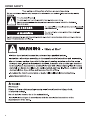
DRYER SAFETY

3
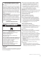
WARNING:
FIRE OR EXPLOSION HAZARD
Failure to follow safety warnings exactly could result in serious injury, death, or property
damage.
Do not store or use gasoline or other ammable vapors and liquids in the vicinity of this
or any other appliance.
–
–
WHAT TO DO IF YOU SMELL GAS:
•
Do not try to light any appliance.
•
Do not touch any electrical switch; do not use any phone in your building.
•
Immediately call your gas supplier from a neighbor’s phone. Follow the gas supplier’s
instructions.
•
If you cannot reach your gas supplier, call the re department.
–
Installation and service must be performed by a qualied installer, service agency, or
the gas supplier.
•
Clear the room, building, or area of all occupants.
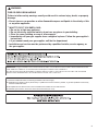
IMPORTANT: The gas installation must conform with local codes, or in the absence of local codes, with the National Fuel Gas
Code, ANSI Z223.1/NFPA 54, or the Natural Gas and Propane Installation Code, CSA B149.1.
The dryer must be electrically grounded in accordance with local codes, or in the absence of local codes, with the National
Electrical Code, ANSI/NFPA 70, or the Canadian Electrical Code, Part 1, CSA C22.1.
In the State of Massachusetts, the following installation instructions apply:
■ Installations and repairs must be performed by a qualified or licensed contractor, plumber, or gas fitter qualified or licensed by
the State of Massachusetts.
■ Acceptable Shut-off Devices: Gas Cocks and Ball Valves installed for use shall be listed.
■ A flexible gas connector, when used, must not exceed 4 feet (121.9 cm).

4
INSTALLATION REQUIREMENTS
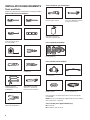
Tools and Parts
Gather the required tools and parts before starting installation.
Tools needed for all installations:
Level
Tape measure Pliers
Flat-blade screwdriver #2 Phillips screwdriver
Adjustable wrench that
opens to 1" (25 mm) or
hex-head socket wrench
Tin snips (new vent
installations)
Caulking gun and
compound (new vent
installations)
1/4" (6 mm) and
5/16" (8 mm) nut driver
(recommended)
Leveling legs (4)
Tools needed for gas installations:
8" (203 mm) or 10"
(254 mm) pipe wrench
8" (203 mm) or 10"
(254 mm) adjustable wrench
(for gas connections)
Pipe-joint compound
resistant to propane gas
Utility knife
“Y” connector
Parts package is located in dryer drum. Check that all parts
are included.
NOTE: Do not use leveling legs supplied with dryer if installing
with a pedestal or a stack kit.
Parts supplied (all models):
Parts needed (steam models):
2' (0.6 m) inlet hose
5' (1.52 m) inlet hose
Parts needed (not supplied with dryer):
■ Vent clamps
■ Vent elbows and vent work
Rubber washer
Wire stripper
(direct wire installations)

5
LOCATION REQUIREMENTS
Check code requirements. Some codes limit, or do not permit,
installing dryer in garages, closets, mobile homes, or sleeping
quarters. Contact your local building inspector.
You will need:
■ A location allowing for proper exhaust installation.
See “Venting Requirements.”
■ A separate 15 or 20 amp circuit for a gas dryer or 30 amp
circuit for an electric dryer.
■ If using power supply cord, a grounded electrical outlet
located within 2 ft. (610 mm) of either side of dryer.
See “Electrical Requirements.”
■ Floor must support dryer weight of 200 lbs. (90.7 kg).
Also consider weight of companion appliance.
■ Cold water faucets located within 4 ft. (1.2 m) of the water
ll valves, and water pressure of 20–120 psi (138–827 kPa).
You may use your washer’s water supply by purchasing the
necessary parts noted in “Parts needed.”
■ Level oor with maximum slope of 1" (25 mm) under entire
dryer. If slope is greater than 1" (25 mm), install Extended
Dryer Feet Kit, Part Number 279810. If not level, clothes
may not tumble properly and automatic sensor cycles may
not operate correctly.
■ For garage installation, place dryer at least 18" (460 mm)
above oor. If using a pedestal, you will need 18" (460 mm)
to bottom of dryer.
■ The dryer must not be installed or stored in an area where
it will be exposed to water and/or weather.
IMPORTANT: Do not operate, install, or store dryer where
it will be exposed to water, weather, or at temperatures below
40°F (4°C). Lower temperatures may cause dryer not to
shut off at end of automatic sensor cycles, resulting in longer
drying times.
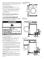
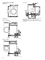
27"
(686 mm)
38
3
/4" Min.
(984 mm)
39" Max.
(990 mm)
Side view:
Front view:
DRYER DIMENSIONS
Additional parts may be required, depending on your installation.
Check local codes. Check existing electrical supply and venting.
Read “Electrical Requirements” and “Venting Requirements”
before purchasing parts.
If using a power supply cord:
Use a UL Listed power supply cord kit marked for use with
clothes dryers. The kit should contain:
■ A UL Listed 30 amp power supply cord, rated 120/240 volt
minimum. The cord should be type SRD or SRDT and be
at least 4 ft. (1.22 m) long. The wires that connect to
the dryer must end in ring terminals or spade terminals
with upturned ends.
■ A UL Listed strain relief.
Optional Equipment (not supplied with dryer):
Refer to your Use and Care Guide for information about
accessories available for your dryer.
*Approx. measurement
Maytag Models
Whirlpool Models
*Approx. measurement
54
1
/2"
(1378 mm)
30
3
/4"
(780 mm)

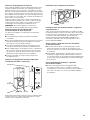
6
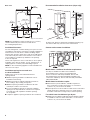
Installation spacing for recessed area
or closet installation
All dimensions show recommended and minimum
spacing allowed.
■ Additional spacing should be considered for ease of
installation and servicing.
■ Additional clearances might be required for wall, door,
oor moldings, dryer venting, and gas line.
■ Additional spacing should be considered on all sides
of the dryer to reduce noise transfer.
■ For closet installation with a door, minimum ventilation
openings in the top and bottom of the door are required.
Louvered doors with equivalent ventilation openings
are acceptable.
■ Companion appliance spacing should also be considered.
Recommended installation clearances (dryer only):
Mobile home installations require:
■ Metal exhaust system hardware, available for purchase
from your dealer. For further information, see “Assistance
or Service” in your Use and Care Guide.
■ Special provisions must be made in mobile homes to introduce
outside air into dryer. Openings (such as a nearby window)
should be at least twice as large as dryer exhaust opening.
For mobile home installation of gas dryers:
■ Mobile Home Installation Hold-down Kit Part Number 346764
is available to order. For further information, see “Assistance
or Service” in your Use and Care Guide.
0" (0 mm) rear spacing is allowed for straight back venting only.
For steam models only, inlet hose must not be kinked.
Installation Clearances
For each arrangement, consider allowing more space for ease
of installation and servicing, spacing for companion appliances,
and clearances for walls, doors, and oor moldings. Space
must be large enough to allow door to fully open. Add spacing
on all sides of dryer to reduce noise transfer. If a closet door
or louvered door is installed, top and bottom air openings
in door are required.
Check code requirements. Some codes limit, or do not permit,
installation of the dryer in garages, closets, mobile homes, or
sleeping quarters. Contact your local building inspector.
NOTE: No other fuel-burning appliance can be installed in the
same closet as a dryer.
Mobile home – Additional installation requirements:
This dryer is suitable for mobile home installations.
The installation must conform to the Manufactured
Home Construction and Safety Standard, Title 24 CFR,
Part 3280 (formerly the Federal Standard for Mobile home
construction and Safety, Title 24, HUD Part 280) or Standard
CAN/CSA-Z240 MH.
Custom under-counter installation:
18" min.
(457 mm)
1"
(25 mm)
24 in.
2
min.
(155 cm
2
)
48 in.
2
min.
(310 cm
2
)
3"
(76 mm)
3"
(76 mm)
1"
(25 mm)
0–5"
(0–127 mm)
Back view:
6
1
/
4
"
(159 mm)
29
7
/8"*
(759 mm)
3
1
/2"*
(89 mm)
5
3
/
4
"*
(146 mm)
6
1
/
8
"*
(156 mm)
14
3
/8"
(365 mm)
25
3
/4"
(654 mm)
3/4"*
(18 mm)
NOTE: Most installations require a minimum of 5" (127 mm)
clearance behind dryer for exhaust vent with elbow.
See “Venting Requirements.”
*Approx. measurement
Gas
Water inlet
(Steam Models Only)
Vent

7
Then choose a 4-wire power supply cord with
ring or spade terminals and UL Listed strain
relief. The 4-wire power supply cord, at least
4 ft. (1.22 m) long, must have four 10-gauge
copper wires and match a 4-wire receptacle
of NEMA Type 14-30R. The ground wire
(ground conductor) may be either green
or bare. The neutral conductor must be
identied by a white cover.
Then choose a 3-wire power supply cord with
ring or spade terminals and UL Listed strain
relief. The 3-wire power supply cord, at least
4 ft. (1.22 m) long, must have three 10-gauge
copper wires and match a 3-wire receptacle
of NEMA Type 10-30R.
4-wire receptacle
(14-30R)
3-wire receptacle
(10-30R)
If connecting by direct wire:
Power supply cable must match power supply (4-wire or 3-wire)
and be:
■ Flexible armored cable or nonmetallic sheathed copper
cable (with ground wire), covered with exible metallic
conduit. All current-carrying wires must be insulated.
■ 10-gauge solid copper wire (do not use aluminum) at least
5 ft. (1.52 m) long.
If your outlet looks like this:
ELECTRICAL REQUIREMENTS –
U.S.A. ONLY
It is your responsibility:
■ To contact a qualied electrical installer.
■ To be sure that the electrical connection is adequate and
in conformance with the National Electrical Code, ANSI/
NFPA 70 – latest edition and all local codes and ordinances.
The National Electrical Code requires a 4-wire power supply
connection for homes built after 1996, dryer circuits involved
in remodeling after 1996, and all mobile home installations.
A copy of the above code standards can be obtained from:
National Fire Protection Association, One Batterymarch Park,
Quincy, MA 02269.
■ To supply the required 3 or 4 wire, single-phase, 120/240
volt, 60 Hz, AC-only electrical supply (or 3 or 4 wire, 120/208
volt electrical supply, if specied on the serial/rating plate)
on a separate 30 amp circuit, fused on both sides of the line.
Connect to an individual branch circuit. Do not have a fuse
in the neutral or grounding circuit.
■ Do not use an extension cord.
■ If codes permit and a separate ground wire is used, it is
recommended that a qualied electrician determine that
the ground path is adequate.
Electrical Connection
To properly install your dryer, you must determine the type of
electrical connection you will be using and follow the instructions
provided for it here.
■ This dryer is manufactured ready to install with a 3-wire
electrical supply connection. The neutral ground conductor
is permanently connected to the neutral conductor (white wire)
within the dryer. If the dryer is installed with a 4-wire electrical
supply connection, the neutral ground conductor must be
removed from the external ground connector (green screw),
and secured under the neutral terminal (center or white wire)
of the terminal block. When the neutral ground conductor is
secured under the neutral terminal (center or white wire) of
the terminal block, the dryer cabinet is isolated from the
neutral conductor. The green ground wire of the 4-wire power
cord must be secured to the dryer cabinet with the green
ground screw.
■ If local codes do not permit the connection of a neutral
ground wire to the neutral wire, see “Optional External Ground
for 3-Wire Connection” in the “Power Supply Cord Connection”
section.
■ A 4-wire power supply connection must be used when the
appliance is installed in a location where grounding through
the neutral conductor is prohibited. Grounding through the
neutral is prohibited for (1) new branch-circuit installations after
1996, (2) mobile homes, (3) recreational vehicles, and (4) areas
where local codes prohibit grounding through the neutral
conductors.
If using a power supply cord:
Use a UL Listed power supply cord kit marked for use with
clothes dryers. The kit should contain:
■ A UL Listed 30 amp power supply cord, rated 120/240 volt
minimum. The cord should be type SRD or SRDT and be
at least 4 ft. (1.22 m) long. The wires that connect to the
dryer must end in ring terminals or spade terminals with
upturned ends.
■ A UL Listed strain relief.

8
ELECTRIC DRYER POWER HOOKUP –
CANADA ONLY
ELECTRICAL REQUIREMENTS
It is your responsibility:
■ To contact a qualied electrical installer.
■ To be sure that the electrical connection is adequate and in
conformance with Canadian Electrical Code, C22.1 – latest
edition and all local codes. A copy of above codes standard
may be obtained from: Canadian Standards Association,
178 Rexdale Blvd., Toronto, ON M9W 1R3 CANADA.
■ To supply the required 4-wire, single-phase, 120/240 volt,
60 Hz, AC-only electrical supply on a separate 30 amp
circuit, fused on both sides of the line. A time-delay fuse or
circuit breaker is recommended. Connect to an individual
branch circuit.
■ This dryer is equipped with a UL Listed
and/or CSA International Certied Power
Cord intended to be plugged into a
standard 14-30R wall receptacle. The
cord is 5 ft. (1.52 m) long. Be sure wall
receptacle is within reach of dryer’s
nal location.
4-wire receptacle
(14-30R)
GROUNDING INSTRUCTIONS
SAVE THESE INSTRUCTIONS
■
For a grounded, cord-connected dryer:
This dryer must be grounded. In the event of malfunction or
breakdown, grounding will reduce the risk of electric shock
by providing a path of least resistance for electric current.
This dryer is equipped with a cord having an equipment-
grounding conductor and a grounding plug. The plug must
be plugged into an appropriate outlet that is properly
installed and grounded in accordance with all local codes
and ordinances.
WARNING: Improper connection of the equipment-
grounding conductor can result in a risk of electric shock.
Check with a qualied electrician or service representative
or personnel if you are in doubt as to whether the dryer is
properly grounded. Do not modify the plug provided with
the dryer: if it will not t the outlet, have a proper outlet
installed by a qualied electrician.
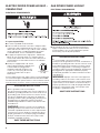
GAS DRYER POWER HOOKUP
ELECTRICAL REQUIREMENTS
■ 120 volt, 60 Hz, AC-only, 15 or 20 amp fused electrical
supply is required. A time-delay fuse or circuit breaker is
recommended. It is also recommended that a separate
circuit serving only this dryer be provided.
If using a replacement power supply cord, it is recommended that
you use Power Supply Cord Replacement Part Number 8529008.
For further information, please reference service numbers located
in the “Assistance or Service” section of your Use and Care Guide.
GROUNDING INSTRUCTIONS
SAVE THESE INSTRUCTIONS
■
For a grounded, cord-connected dryer:
This dryer must be grounded. In the event of malfunction or
breakdown, grounding will reduce the risk of electric shock
by providing a path of least resistance for electric current.
This dryer is equipped with a cord having an equipment-
grounding conductor and a grounding plug. The plug must
be plugged into an appropriate outlet that is properly
installed and grounded in accordance with all local codes
and ordinances.
WARNING: Improper connection of the equipment-
grounding conductor can result in a risk of electric shock.
Check with a qualied electrician or service representative
or personnel if you are in doubt as to whether the dryer is
properly grounded. Do not modify the plug provided with
the dryer: if it will not t the outlet, have a proper outlet
installed by a qualied electrician.

9
†
®
TEFLON is a registered trademark of Chemours.
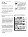
Option 2 (Alternate Method)
Approved aluminum or copper tubing:
■ Must include 1/8" NPT minimum plugged tapping accessible
for test gauge connection, immediately upstream of the gas
connection to the dryer. See illustration below.
■ 1/2" IPS pipe is recommended.
■ 3/8" approved aluminum or copper tubing is acceptable for
lengths under 20 ft. (6.1 m) if local codes and gas supplier
permit.
■ If you are using natural gas, do not use copper tubing.
■ Lengths over 20 ft. (6.1 m) should use larger tubing and
a different size adapter tting.
■ If your dryer has been converted to use propane gas, 3/8"
propane compatible copper tubing can be used. If the total
length of the supply line is more than 20 ft. (6.1 m), use
larger pipe.
NOTE: Pipe-joint compounds that resist the action
of propane gas must be used. Do not use TEFLON
®†
tape.
■ Must include shut-off valve.
In the U.S.A.:
An individual manual shut-off valve must be installed within
six (6) ft. (1.8 m) of the dryer in accordance with the National
Fuel Gas Code, ANSI Z223.1. The location should be easy
to reach for opening and closing.
In Canada:
An individual manual shut-off valve must be installed in
accordance with the B149.1, Natural Gas and Propane
Installation Code. It is recommended that an individual
manual shut-off valve be installed within six (6) ft. (1.8 m)
of the dryer. The location should be easy to reach for
opening and closing.
A. 3/8" exible gas connector
B. 3/8" pipe to are adapter tting
C. 1/8" NPT minimum plugged tapping
D. 1/2" NPT gas supply line
E. Gas shut-off valve
A
B
E
D
C
GAS SUPPLY REQUIREMENTS
WARNING
Explosion Hazard
Use a new CSA International approved gas supply line.
Install a shut-off valve.
Securely tighten all gas connections.
If connected to propane, have a qualied person make
sure gas pressure does not exceed 13" (330 mm) water
column.
Examples of a qualied person include:
licensed heating personnel,
authorized gas company personnel, and
authorized service personnel.
Failure to do so can result in death, explosion, or re.
GAS TYPE
Natural Gas:
This dryer is equipped for use with natural gas. It is certied
by UL for use with propane gas with appropriate conversion.
■ Your dryer must have the correct burner for the type of gas
in your home. Burner information is located on the rating plate
in the door well of your dryer. If this information does not agree
with the type of gas available, contact your dealer or call the
phone numbers referenced in the “Assistance or Service”
section of your Use and Care Guide.
Propane Gas Conversion:
IMPORTANT: Conversion must be made by a qualied
technician.
No attempt shall be made to convert the appliance from the gas
specied on the model/serial rating plate for use with a different
gas without consulting your gas company.
GAS SUPPLY LINE
Option 1 (Recommended Method)
Flexible stainless steel gas connector:
■ If local codes permit, use a new exible stainless steel gas
connector (Design Certied by the American Gas Association
or CSA International) to connect your dryer to the rigid gas
supply line. Use an elbow and a 3/8" are x 3/8" NPT adapter
tting between the stainless steel gas connector and the
dryer gas pipe, as needed, to prevent kinking.

10
*5
3
/4"
(146 mm)
1
1
/2"
(38 mm)
3/8" NPT dryer gas pipe
GAS SUPPLY CONNECTION REQUIREMENTS
■ Use an elbow and a 3/8" are x 3/8" NPT adapter tting
between the exible gas connector and the dryer gas
pipe, as needed to avoid kinking.
■ Use only pipe-joint compound. Do not use TEFLON
®
tape.
■ This dryer must be connected to the gas supply line with a
listed exible gas connector that complies with the standard
for connectors for gas appliances, ANSI Z21.24 or CSA 6.10.
BURNER INPUT REQUIREMENTS
Elevations above 2,000 ft. (610 m):
■ When installed above 2,000 ft. (610 m) a 4% reduction of the
burner Btu rating shown on the model/serial number plate is
required for each 1,000 ft. (305 m) increase in elevation.
Gas supply pressure testing
■ The dryer must be disconnected from the gas supply
piping system during pressure testing at pressures greater
than 1/2 psi.
DRYER GAS PIPE
■ The gas pipe that comes out through the rear of your dryer has
a 3/8" male pipe thread.
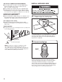
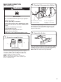
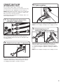
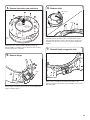
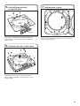
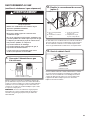
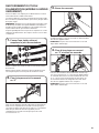
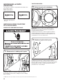
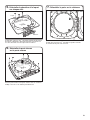
INSTALL LEVELING LEGS
To avoid damaging oor, use a large at piece of cardboard
from dryer carton; place under entire back edge of dryer.
Firmly grasp dryer body (not console panel) and gently lay
dryer down on cardboard.
Examine leveling legs and locate the diamond marking.
Screw legs into leg holes by hand – use a wrench to nish
turning legs until diamond marking is no longer visible.
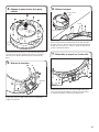
Place a carton corner post from dryer packaging under each
of the two dryer back corners. Stand the dryer up. Slide the
dryer on the corner posts until it is close to its nal location.
Leave enough room to connect the exhaust vent.
1. Prepare dryer for leveling legs
2. Screw in leveling legs
diamond
marking
* NOTE: If the dryer is mounted on a pedestal, the gas
pipe height must be an additional 10" (254 mm) or
15.5" (394 mm) from the oor, depending on the pedestal
model. For a garage installation, the gas pipe height must
be an additional 18" (460 mm) from the oor.
Diamond
marking

11
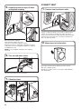
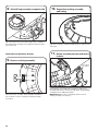
MAKE ELECTRICAL CONNECTION –
U.S.A. ONLY
ELECTRICAL CONNECTION
Power Supply Cord:
1. Choose electrical connection type
Power supply cord 4-wire receptacle
(NEMA Type 14-30R).
Go to “Power Supply Cord Connection.”
3-wire direct connection:
Go to “Direct Wire Connection.”
4-wire direct connection:
Go to “Direct Wire Connection.”
Power supply cord 3-wire receptacle
(NEMA Type 10-30R).
Go to “Power Supply Cord Connection.”
NOTE: If local codes do not permit connection of a
cabinet-ground conductor to neutral wire, go to “Optional
External Ground for 3-Wire Connection.” This connection
may be used with either a power supply cord or a direct
wire connection.
Before you start: disconnect power.
For direct wire installations:
Remove hold-down screw and terminal block cover.
2. Remove terminal block cover

12
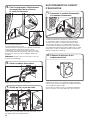
Power supply cord strain relief
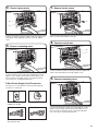
Power Supply Cord Connection
2. Attach power supply cord
to strain relief
1. Attach power supply cord strain relief
D
C
B
A
Put power supply cord through the strain relief. Be sure that
the wire insulation on the power supply cord is inside the
strain relief. The strain relief should have a tight t with the
dryer cabinet and be in a horizontal position. Do not further
tighten strain relief screws at this point.
Remove the screws from a 3/4" (19 mm) UL Listed strain relief.
Put the tabs of the two clamp sections (C) into the hole below
the terminal block opening (B) so that one tab is pointing
up (A) and the other is pointing down (D), and hold in place.
Tighten strain relief screws just enough to hold the two clamp
sections (C) together.
Power supply cord 4-wire receptacle
(NEMA Type 14-30R):
Go to “4-Wire Power Supply Cord
Connection” on this page.
Power supply cord 3-wire receptacle
(NEMA Type 10-30R):
Go to “3-Wire Power Supply Cord
Connection” on page 13.
If your outlet looks like this:
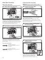
4-Wire Power Supply Cord Connection
4-wire receptacle
(NEMA type 14-30R)
4 prong plug
Spade terminals
with upturned ends
Ring terminals
IMPORTANT: A 4-wire connection is required for mobile homes
and where local codes do not permit the use of 3-wire connections.
1. Prepare to connect neutral ground
wire and neutral wire
E
B
A
2. Connect neutral ground wire
and neutral wire
C
E
B
Remove center terminal block screw (B). Remove neutral
ground wire (E) from green external ground conductor screw (A).
Connect neutral ground wire (E) and neutral wire (white or
center) (C) of power supply cord under center terminal block
screw (B). Tighten screw.

13
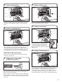
3-wire receptacle
(NEMA type 10-30R)
3 prong plug
Spade terminals
with upturned ends
Ring terminals
4. Connect remaining wires
3. Connect ground wire
F
A
Connect remaining wires under outer terminal block screws.
Tighten screws. Finally, reinsert tab of terminal block cover
into slot of dryer rear panel. Secure cover with hold-down
screw. Now go to “Venting Requirements.”
Connect ground wire (F) (green or bare) of power supply cord
under green external ground conductor screw (A). Tighten
screw.
3-Wire Power Supply Cord Connection
Use where local codes permit connecting cabinet-ground
conductor to neutral wire.
3. Connect remaining wires
2. Connect neutral wire
C
B
1. Remove center screw
B
Connect remaining wires under outer terminal block screws.
Tighten screws. Finally, reinsert tab of terminal block cover
into slot of dryer rear panel. Secure cover with hold-down
screw. Now go to “Venting Requirements.”
Connect neutral wire (white or center) (C) of power supply cord
under center terminal block screw (B). Tighten screw.
Remove center terminal block screw (B).

14
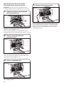
Direct Wire Connection
Direct wire strain relief
1. Attach direct wire strain relief
C
B
A
2. Attach direct wire cable to strain relief
Unscrew the removable conduit connector (A) and any
screws from a 3/4" (19 mm) UL Listed strain relief. Put the
threaded section of the strain relief (C) through the hole below
the terminal block opening (B). Reaching inside the terminal
block opening, screw the removable conduit connector (A)
onto the strain relief threads and tighten securely.
Put direct wire cable through the strain relief. The strain
relief should have a tight t with the dryer cabinet and be in
a horizontal position. Tighten strain relief screw against the
direct wire cable.
3-wire direct connection:
Go to “3-Wire Direct Wire Connection”
on page 15.
4-wire direct connection:
Go to “4-Wire Direct Wire Connection”
on this page.
If your wiring looks like this:
4-Wire Direct Wire Connection
IMPORTANT: A 4-wire connection is required for mobile homes
and where local codes do not permit 3-wire connections.
1. Prepare your 4-wire cable
for direct connection
1"
(25 mm)
3
1
⁄
2
"
(89 mm)
5"
(127 mm)
2. Prepare to connect neutral ground
wire and neutral wire
E
B
A
Remove center terminal block screw (B). Remove neutral
ground wire (E) from green external ground conductor screw (A).
Direct wire cable must have 5 ft. (1.52 m) of extra length so
dryer may be moved if needed.
Strip 5" (127 mm) of outer covering from end of cable,
leaving bare ground wire at 5" (127 mm). Cut 1
1
/
2
" (38 mm)
from remaining three wires. Strip insulation back 1" (25 mm).
Shape ends of wires into hooks.
3. Connect neutral ground wire
and neutral wire
C
E
B
Connect neutral ground wire (E) and place
hooked end (hook facing right) of neutral wire
(white or center wire) (C) of direct wire cable
under center screw of terminal block (B).
Squeeze hooked ends together and tighten screw.

15
1. Prepare your 3-wire cable
for direct connection
1"
(25 mm)
3½"
(89 mm)
5. Connect remaining wires
4. Connect ground wire
F
A
Direct wire cable must have 5 ft. (1.52 m) of extra length so
dryer may be moved if needed.
Strip 3
1
/
2
" (89 mm) of outer covering from end of cable. Strip
insulation back 1" (25 mm). If using 3-wire cable with ground
wire, cut bare wire even with outer covering. Shape wire ends
into hooks.
Connect ground wire (green or bare) (F) of direct wire cable
under green external ground conductor screw (A). Tighten
screw.
Place hooked ends of remaining direct wire cable wires under
outer terminal block screws (hooks facing right). Squeeze
hooked ends together and tighten screws. Finally, reinsert tab
of terminal block cover into slot of dryer rear panel. Secure
cover with hold-down screw. Now go to “Venting Requirements.”
3-Wire Direct Wire Connection
Use where local codes permit connecting cabinet-ground
conductor to neutral wire.
2. Remove center screw
B
Remove center terminal block screw (B).
3. Connect neutral wire
C
B
Place hooked end of neutral wire (white
or center) (C) of direct wire cable under
center terminal block screw (B), hook
facing right. Squeeze hooked end together.
Tighten screw.
4. Connect remaining wires
Place hooked ends of remaining direct wire cable wires under
outer terminal block screws (hooks facing right). Squeeze
hooked ends together and tighten screws. Finally, reinsert tab
of terminal block cover into slot of dryer rear panel. Secure
cover with hold-down screw. Now go to “Venting Requirements.”

16
Connect neutral ground wire (E) and neutral wire (white or
center wire) (C) of power supply cord or cable under center
terminal block screw (B). Tighten screw.
Place ends of remaining wires under outer terminal block
screws. Tighten screws.
Optional External Ground for 3-Wire
Connection (Power Supply Cord Shown)
IMPORTANT: You must verify with a qualied electrician
that this grounding method is acceptable before connecting.
2. Connect neutral ground wire
and neutral wire
C
E
B
1. Prepare to connect neutral ground
wire and neutral wire
E
B
A
3. Connect remaining wires
Install the correct strain relief for your electrical connection
method, as shown on page 12 or 14.
Remove center terminal block screw (B). Remove neutral
ground wire (E) from green external ground conductor screw (A).
Connect a separate copper ground wire (G) under the green
external ground conductor screw (A) to an adequate ground.
Finally, reinsert tab of terminal block cover into slot of dryer
rear panel. Secure cover with hold-down screw. Now go to
“Venting Requirements.”
4. Connect external ground wire
G
A

17
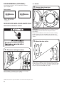
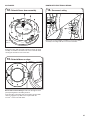
A
B
1. Connect gas supply to dryer
Remove red cap from gas pipe. Using a wrench to tighten,
connect gas supply to dryer. Use pipe-joint compound
on threads of all non-ared male ttings. If exible metal
tubing is used, be sure there are no kinks.
NOTE: For propane gas connections, you must use
pipe-joint compound resistant to action of propane gas.
Do not use TEFLON
®
tape.
A. Flared male tting
B. Non-ared male tting
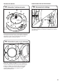
A
B
C
D
2. Plan pipe tting connection (Option 1)
A combination of pipe ttings must be used to connect dryer
to existing gas line. A recommended connection is shown.
Your connection may be different, according to supply line
type, size, and location.
A. 3/8" exible gas connector
B. 3/8" dryer gas pipe
C. 3/8" to 3/8" pipe elbow
D. 3/8" pipe-to-are adapter
tting
3. Open shut-off valve
Open shut-off valve in supply line; valve is open when handle
is parallel to gas pipe. Then, test all connections by brushing
on an approved noncorrosive leak-detection solution.
Bubbles will show a leak. Correct any leak found.
A. Closed valve
B. Open valve
MAKE GAS CONNECTION
(Gas models only)
A
B
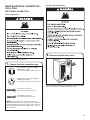
WARNING
Explosion Hazard
Use a new CSA International approved gas supply line.
Install a shut-off valve.
Securely tighten all gas connections.
If connected to propane, have a qualied person make
sure gas pressure does not exceed 13" (330 mm) water
column.
Examples of a qualied person include:
licensed heating personnel,
authorized gas company personnel, and
authorized service personnel.
Failure to do so can result in death, explosion, or re.

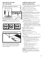
18
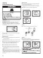
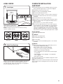
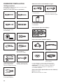
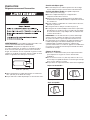
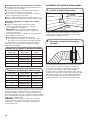
Louvered Hood
Angled Hood
Box Hood
Exhaust hoods:
■ An exhaust hood should cap the vent to keep rodents and
insects from entering the home.
■ Must be at least 12" (305 mm) from ground or any object
that may obstruct exhaust (such as owers, rocks, bushes,
or snow).
■ Do not use an exhaust hood with a magnetic latch.
Elbows:
Recommended Styles:
■ 45° elbows provide better airow than 90° elbows.
Clamps:
■ Use clamps to seal all joints.
■ Exhaust vent must not be connected or secured with screws
or other fastening devices that extend into interior of duct
and catch lint. Do not use duct tape.
Good Better
Acceptable Style:
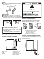
Venting Requirements
VENTING
WARNING: To reduce the risk of re, this dryer MUST BE
EXHAUSTED OUTDOORS.
IMPORTANT: Observe all governing codes and ordinances.
Dryer exhaust must not be connected into any gas vent,
chimney, wall, ceiling, attic, crawlspace, or a concealed space
of a building. Only rigid or exible metal vent shall be used
for exhausting.
■ Only a 4" (102 mm) heavy metal exhaust vent and clamps
may be used.
■ Do not use plastic or metal foil vent.
Rigid metal vent:
■ Recommended for best drying performance and to avoid
crushing and kinking.
Flexible metal vent: (Acceptable only if accessible to clean)
■ Must be fully extended and supported in nal dryer location.
■ Remove excess to avoid sagging and kinking that may
result in reduced airow and poor performance.
■ Do not install in enclosed walls, ceilings, or oors.
■ The total length should not exceed 7¾ ft. (2.4 m).
■ The length of exible metal vent used must be included
in the overall vent system design as shown in the “Vent
System Charts.”
NOTE: If using an existing vent system, clean lint from entire
length of the system and make sure exhaust hood is not plugged
with lint. Replace plastic or metal foil vents with rigid metal
or exible metal vents. Review “Vent System Charts” and, if
necessary, modify existing vent system to achieve best drying
performance.
4"
(102 mm)
4" (102 mm) heavy metal exhaust vent

19
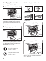
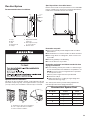
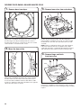
Plan Vent System
Recommended exhaust installation:
A. Dryer
B Elbow
C. Wall
D. Exhaust hood
E. Clamps
F. Rigid metal or exible
metal vent
G. Vent length necessary
to connect elbows
H. Exhaust outlet
A
B C
D
E
F
B
G
H
Optional exhaust installations:
This dryer can be converted to exhaust out the right side, left side
(all models except long vent), or through the bottom. If you prefer,
you may contact your local dealer to have the dryer converted.
A. Standard rear offset exhaust installation
B. Left- or right-side exhaust installation
C. Bottom exhaust installation
A B C
The “Vent System Charts” provide venting requirements
that will help achieve best drying performance.
Standard Vent System Chart
Number of
90° elbows
Type
of vent
Angled
hoods
0
Rigid metal 64 ft. (20 m)
1
Rigid metal 54 ft. (16.5 m)
2
Rigid metal 44 ft. (13.4 m)
3
Rigid metal 35 ft. (10.7 m)
4
Rigid metal 27 ft. (8.2 m)
Special provisions for mobile homes:
Exhaust vent must be securely fastened to a noncombustible
portion of mobile home and must not terminate beneath the
mobile home. Terminate exhaust vent outside.
Determine vent path:
■ Select route that will provide straightest and most direct
path outdoors.
■ Plan installation to use fewest number of elbows and turns.
■ When using elbows or making turns, allow as much room
as possible.
■ Bend vent gradually to avoid kinking.
■ Use as few 90° turns as possible.
Determine vent length and elbows needed for best
drying performance:
■ Use the following “Vent System Charts” to determine type
of vent material and hood combinations acceptable to use.
NOTE: Do not use vent runs longer than those specied
in “Vent System Charts.”
Exhaust systems longer than those specied will:
■ Shorten life of dryer.
■ Reduce performance, resulting in longer drying times
and increased energy usage.

20
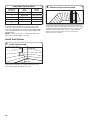
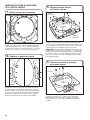
Install Vent System
1. Install exhaust hood
12" min.
(305 mm)
12" min.
(305 mm)
2. Connect vent to exhaust hood
Install exhaust hood and use caulking compound to seal
exterior wall opening around exhaust hood.
Vent must t over the exhaust hood. Secure vent to exhaust
hood with 4" (102 mm) clamp. Run vent to dryer location using
straightest path possible. Avoid 90° turns. Use clamps to seal
all joints. Do not use duct tape, screws, or other fastening
devices that extend into interior of vent to secure vent,
because they can catch lint.
To determine if your model has a long vent system, refer
to the type code located on the serial number plate in the
inner door well. Example: An electric model would be DALV
– ELE – XXXXXXX-XXX. A gas model would be DALV – NAT –
XXXXXXX-XXX.
NOTE: For long vent systems, use of box/louvered hoods
will improve venting regardless of length.
Long Vent System Chart
Number of
90° elbows
Type
of vent
Angled
hoods
0
Rigid metal 160 ft. (48.8 m)
1
Rigid metal 150 ft. (45.7 m)
2
Rigid metal 140 ft. (42.7 m)
3
Rigid metal 130 ft. (39.6 m)
4
Rigid metal 120 ft. (36.6 m)
La page est en cours de chargement...
La page est en cours de chargement...
La page est en cours de chargement...
La page est en cours de chargement...
La page est en cours de chargement...
La page est en cours de chargement...
La page est en cours de chargement...
La page est en cours de chargement...
La page est en cours de chargement...
La page est en cours de chargement...
La page est en cours de chargement...
La page est en cours de chargement...
La page est en cours de chargement...
La page est en cours de chargement...
La page est en cours de chargement...
La page est en cours de chargement...
La page est en cours de chargement...
La page est en cours de chargement...
La page est en cours de chargement...
La page est en cours de chargement...
La page est en cours de chargement...
La page est en cours de chargement...
La page est en cours de chargement...
La page est en cours de chargement...
La page est en cours de chargement...
La page est en cours de chargement...
La page est en cours de chargement...
La page est en cours de chargement...
La page est en cours de chargement...
La page est en cours de chargement...
La page est en cours de chargement...
La page est en cours de chargement...
-
 1
1
-
 2
2
-
 3
3
-
 4
4
-
 5
5
-
 6
6
-
 7
7
-
 8
8
-
 9
9
-
 10
10
-
 11
11
-
 12
12
-
 13
13
-
 14
14
-
 15
15
-
 16
16
-
 17
17
-
 18
18
-
 19
19
-
 20
20
-
 21
21
-
 22
22
-
 23
23
-
 24
24
-
 25
25
-
 26
26
-
 27
27
-
 28
28
-
 29
29
-
 30
30
-
 31
31
-
 32
32
-
 33
33
-
 34
34
-
 35
35
-
 36
36
-
 37
37
-
 38
38
-
 39
39
-
 40
40
-
 41
41
-
 42
42
-
 43
43
-
 44
44
-
 45
45
-
 46
46
-
 47
47
-
 48
48
-
 49
49
-
 50
50
-
 51
51
-
 52
52


