
NV-T2SIR
Dual SIRIUS
®
-Ready/AM/FM Tuner
Installation Guide


FRENCH
DURE EN HEURES PAR JOUR 8 6 4 3 2 1
INIVEAU SONORE CONTINU EN dB 90 93 95 97 100 103
Danger
L‘exposition a des niveaux eleves de bruit peut provoquer une perte
permanente de l’audition, Chaque organisme humain reagit
differemment quant a la perte de l’audition, mais quasiment tout le
monde subit une diminution de I’acuite auditive lors d’une exposition
suffisamment longue au bruit intense. Les autorites competentes en
reglementation de bruit ont defini les expositions tolerees aux niveaux
de bruits:
Selon les autorites, toute exposition dans les limites citees ci-dessus,
peuvent provoquer certaines pertes d’audition. Des bouchons ou
protections dans l’appareil auditif ou sur l’oreille doivent etre portes lors
de l’utilisation de ce systeme d’amplification afin de prevenir le risque
de perte permanente de l’audition, Dans le cas d’expositions
superieures aux limites precitees il est recommande, afin de se
premunir contre les expositions aux pressions acoustiquese I evees
potentielIement dangeure u ses, aux personnes exposees aux
equipements capables de delivrer de telles puissances, tels ce
systeme d’amplification en fonctionnement, de proteger l’appareil
auditif.
ATTENTION: AFIN DE LlMlTER LE RISQUE DE CHO ELECTR/QUE, NE
PAS ENLEVER LE CHASSIS. NE CONTIENT PAS DE
PIECES POUVANT ETRE REPAREE PAR L’UTILISATEUR.
CONFER LE SERVICE APRES-VENTE AUX
REPARATEURS
ATTENTION
RISQUE DE CHOC ELECTRIQUE
NE PAS OUVRIR.
CE SYMBOLE A POUR BUT D'AVERTIR L'UTILISATEUR DE LA PRESENCE
DE VOLTAGE DANGEREUX NON-ISOLE A L'INTERIEUR DE CE PRODUIT
QUI PEUT ETRE DE PUISSANCE SUFFISAMMENT IMPORTANTE POUR
PROVOQUER UN CHOC ELECTRIQUE AUX PERSONNES.
CE SYMBOLE A POUR BUT D'AVERTIR L'UTILISATEUR DE LA PRESENCE
D'INSTRUCTIONS D'UTILISATION ET DE MAINTENANCE DANS LES
DOCUMENTS FOURNIS AVEC CE PRODUIT.
IMPORTANTES INSTRUCTIONS DE SECURITE
1. Lire avec attention toutes les recommandations et précautions
d'emploi avant d'utiliser ce produit.
2. Toutes les recommandations et précautions d'emploi doivent être
conservées afin de pouvoir s'y reporter si nécessaire.
3. Lire et comprendre tous les avertissements énumérés dans les
précautions d'emploi.
4. Suivre toutes les précautions d'emploi pour utiliser ce produit.
5. Ce produit ne doit pas être utilisé près d'eau, comme par exemple
baignoires, éviers, piscine, sous-sol humides ... Etc.
6. Utiliser exclusivement un chiffon sec pour nettoyer ce produit.
7. Ne bloquér aucune ouverture de ventilation. Ne pas placer le
produit tout contre un mur ou dans une enceinte fernée, cela
gênerait le flux d'air nécessaire au refroidissement.
8. Ne pas placer le produit près de toute source de chaeur telle que
radiateurs, arrivées d'air chaud, fourneaux ou autres appareils
générant de la chaleur (incluant les amplificateurs producteurs
de chaleur) .
9. Ne pas négliger la sécurité que procure un branchement polarisé
ou avec raccordement à la terre, Un branchement polarisé
comprend deux fiches dont l'une est plus large que l'autre. Un
branchement à la terre comprend deux fiches plus une troisième
reliée à la terre. Si la fiche secteur fournie ne s'insert pas dans
votre prise de courant. consulter un 'électricien afin de remplacer
votre prise obsolète.
10. Protéger le cordon d'alimentation de tout écrasement ou
pincement, particulièrement au niveau des fiches, des
réceptacles utilisés et à l'endroit de sortie de l'appareil. Ne pas
casser la fiche de terre du cordon d'alimentation.
11. Utiliser uniquement les accessoires spécifiés par le constructeur.
12. Utiliser uniquement avec le chariot de transport, le support, le
trépied, la console ou la table spécifiés par le constructeur ou
vendus avec l'appareil. Lors de l'utilisation d'un chariot, bouger
avec précaution l'ensemble chariotlappareil afin d'éviter les
dommages d'un renversement.
13 Débrancher cet appareil lors d'orages ou s'il n'est pas utilisé
pendant une longue période.
14. Des précautions doivent être prises afin qu'aucun objet ne tombe
et qu'aucun liquide ne se répande à l'intérieur de l'appareil par
les orifics de ventilation ou n'importe quelle autre ouverture.
15. Pour toutes interventions techniques s'adresser à un technicien
qualifié.L'intervention technique est nécessaire lorsque l'appareil
a été endommagé de n'importe quelle façon, comme par
exemple si le cordon secteur ou sa fiche sont détériorés,si du
liquide a coulé ou si des objets sont tombés à l'intérieur de
l'apparei1,si l'appareil a été exposé à la pluie ou à l'humidité, s'il
ne fonctionne pas normalement ou s'il est tombé.
16. ATTENTI0N:Pour réduire le risque d'incendie ou de choc
electrique ne pas exposer l'appareil à la pluie ou à l'humidité.
AFIN DE REDUIRE LES RISQUÉ D'INCENDIE ET DE DECHARGE
ELECTRIQUE, NE PAS EXPOSER CET APPAREIL A LA PLUIE OU A
L'HUMIDITE.

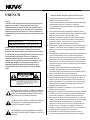
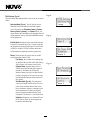
GROUND
CLAMPS
ELECTRIC
SERVICE
ENTRANCE
ANTENNA
DISCHARGE UNIT
NEC SECTION
810-20
GROUNDING
CONDUCTORS
GROUND CLAMPS
POWER SERVICE
GROUPING ELECTRODE
SYSTEM NEC ART 250
PART H
NEC NATIONAL ELECTRICAL CODE
ANTENNA
LEAD-IN
WIRE

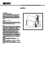
Introduction
Congratulations on your purchase of the NuVo T2SIR Dual SIRIUS Ready /AM/FM Tuner. Enjoying broadcast music throughout the
st
home has moved into the 21 century with NuVo’s T2 Dual Tuner solutions. Whether your preference is traditional AM/FM listening,
or SIRIUS Satellite Radio, the T2SIR offers an affordable, specially designed component for whole-home distribution.
The T2SIR’s internal NuVoNet communication allows for very unique and complete feedback to all of the NuVo Control Pads.
1
Table of Contents:
Basic Features
I. Installing the T2SIR in the Home
Setting the Audio Outputs for NuVoNet or
II. T2SIR Use with SIRIUS Radio
III. T2SIR Front Panel Menu
T2SIR Quick Setup Guide for Use with NuVoNet page 2
Front Panel page 4
Back Panel page 5
NV-T2RC4 Remote Control page 6
Connecting the Audio Outputs page 7
Standalone use page 7
AM/FM Antenna Installation page 7
Connecting for NuVoNet Use page 8
IR Control of the T2SIR page 8
RS232 Serial Control page 9
The SIRIUS 8-pin Connector page 9
SIRIUS Modules and Subscription page 9
Installing the SIRIUS Antenna page 10
Bands page 10
Channels page 11
SIRIUS Info page 11
T2SIR Options page 11
Edit Presets page 11
Tuning Mode page 12
Skipped Channels page 12
T2SIR Settings page 13
Operating Mode page 13
Enabled Bands page 13
Tuning page 13
Diagnostics page 14
Audio Test page 14
Reset Memory page 14
IV. NuVoNet Control of the T2SIR
V. Using the Tuner Configurator Software
Advanced Settings
Tuning Up and Down page 15
Selecting a Locked Channel page 15
Changing Bands page 15
Tuning Modes page 15
Selecting Tuner A and B page 15
Control Pad Main Menu page 16
T2SIR Options page 16
1.0 Start page 18
2.0 Config page 18
3.0 Presets page 20
4.0 Advanced Config page 22
5.0 Update System page 23
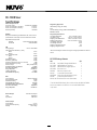
NV-T2SIR Specifications page 24

2
T2SIR Quick Setup Guide for Use With NuVoNet
The T2SIR Dual Tuner is the perfect broadcast music solution for whole-home audio. The internal NuVoNet capability of the T2SIR
allows it to easily communicate in real time with the NuVo Grand Concerto and Essentia E6G Control Pads. The following is a step-
by-step guide for setting up and installing the T2SIR for use with the Grand Concerto and Essentia NuVoNet Suites.
Step 1: Upon unpacking your T2SIR Tuner, establish which audio inputs, 1-6, the T2’s A and B audio outputs will represent. Plug
the T2 into an AC power source.
Step 2: Attach the audio outputs A and B of the Tuner to the appropriate numbered inputs on the Grand Concerto or Essentia
System.
Step 3: Connect the CAT5 from the NuVoNet output on the rear panel of the Tuner to one of the Device inputs on the Grand Concerto
EZ Port or the Essentia Allport. This will enable communication to the System’s Control Pads. Note that a single CAT5 connection
provides information from both Tuners A and B. A final CAT5 Connection should then be made to the NuVoNet CAT5 input on the
back panel of the Grand Concerto or Essenita main amplifier for the NuVoNet RJ45 on the Grand Concerto EZ Port or the Essentia
Allport. This completes the necessary connection for the NuVoNet communication.
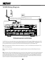
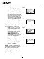
T2SIR Wiring Diagram
IN
OUT1 OUT2
MODEL SRS-2V8
2300-2400 MHZ
072 8
303 3118
R
T
E
E
T
K
N
I
CM
Model NV- T2S IR
Dua l SIRIU S Ready AM /FM Tune r
www. nuvo tech nolo gies .com
NuVo Techno log ies LL C Hebron , KY USA •
CONF ORMS TO UL
STD. 6006 5 CERTIF IED
TO CAN /CSA STD .
C22. 2 No.6 0065:0 6
RS 232
SYSTE M
ANTEN NA
IN
NuVoNet
USE N V-T2 DAA WIT H
OPT IONAL NV-T2 FXC
AND SIRI US ANTE NNA
IR INPUT
L
AUDIO
R
TUNER A
SIRIUS
L
AUDIO
R
TUNER B
RoHS
SIRIUS
R
OUTPUT POWER
OUTPUT POWER
20W/6OHM X2
20W/6OHM X2
SYS ON
EXT. MUTE
L
R
L
R
L
R
VARI ABLE
OUT PUT
FIX ED
OUT PUT
SUM1
3033 118
C
US
CON FORMS TO
UL STD .6500
CER TIFIE D TO
CAN /CSA STD .E600 65
NuVo Tech nolog ies Cin cinna ti Ohio U SA
FUS E:T5 A
120 V 60Hz 50 0W
MODE L NV-I8D M
SIX SO URCE EI GHT ZON E
AUDI O DISTR IBUTI ON SYST EM
www. nuvot echno logie s.com
OUTPUT POWER
OUTPUT POWER
OUTPUT POWER
20W/6OHM X2
20W/6OHM X2
20W/6OHM X2
TIP =L
RIN G=R
VARI ABLE
OUT PUT
FIX ED
OUT PUT
TIP =L
RIN G=R
VARI ABLE
OUT PUT
FIX ED
OUT PUT
TIP =L
RIN G=R
VARI ABLE
OUT PUT
FIX ED
OUT PUT
TIP =L
RIN G=R
VARI ABLE
OUT PUT
FIX ED
OUT PUT
TIP =L
RIN G=R
VARI ABLE
OUT PUT
VARI ABLE
OUT PUT
FIX ED
OUT PUT
FIX ED
OUT PUT
TIP =L
RIN G=R
TIP =L
RIN G=R
1 2 3 4 5
6
1 2 3 4 5
6
2 3
4
1 2 3
RS-232
CON NECT TO
NV-I 8X
USE N V-SLC1
CAB LE
CON NECT TO
NV-I 8X
USE N V-SLC1
CAB LE
CON NECT TO
NV-I 8EZP1
USE N V-NC1
CAB LE
USE CNLY WITH 250V FUSE
4
5
6
SUM2
5 6 7
8
OUTPUT POWER
20W/6OHM X2
ZONE 6Z ONE 6
ZONE 7&8
SYSTEM
ZONE TRIGGER OUTPUTS
SOURCE LINK
SOURCE INPUTS
ZONE 1
NETWORK
EMITTER OUTPUTS DIGITAL LI NK
ZONE 3
ZONE 4
ZONE 5
ZONE 2
PROGRAM
6
4
5
3
1
2
SOURCE STATUS INPUT S
1
MENU
OK
Modern Rock
Drift-Follow Th
Living For
AM/FM
3:09 pm
AM/FM
ANTENNA IN
XM
ANTENNA IN
COMBINED
ANTENNA OUT
NV-T2FXC SIGNAL
COMBINER
AM/FM
ANTENNA IN
XM
ANTENNA IN
COMBINED
ANTENNA OUT
NV-T2FXC SINGNAL
COMBINER
Diagram shown using the Grand Concerto System
Diagram shown using an optional NV-SCH-ANT SIRIUS Outdoor Antenna
and two SIRIUS NV-SCH1 Home Tuners.
Conc erto EZ Po rt
Mode l NV-I8GE ZP
Device 2 Devi ce 3
Device 4 Devi ce 5 Device 6
Conn ect to
NV-I8 GM
www.nuv otech nolog ies.co m
NuVo Techno logies LLC He bron, Ke ntuck y USA
Device 1

3
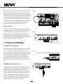
Step 4: Complete the antenna connections on the back panel of the Tuner using standard RG6 coaxial cable. Quad shielded cable is
recommended. When the antennas are connected, the Tuner will begin receiving a signal for both Tuners A and B.
Step 5: When the Tuner is plugged into an AC power source, the front panel display will move through a boot procedure. When this
procedure is completed, a message, Uninitialized State Detected will appear.
Step 6: Following the prompt from the display, touch the OK button on the Tuner’s front panel control. This will display a regional
tuning selection: USA and Canada, Western Europe, Australia, and New Zealand. Make the appropriate selection to match the
Tuner s geographic location.
Step 7: Touching OK on the front panel controls will prompt a second screen on the display. This will read, Set Tuner A Mode,
Standalone, Source 1, Source 2, Source 3, Source 4, Source 5, and Source 6. The top selection, Standalone, will be highlighted. This
choice is used for any purpose that is not NuVoNet communication. Using the down arrow on the far right of the front panel
controls, scroll to the desired source input number and touch OK to select. The display will automatically go to Tuner B setup.
Repeat the above steps for setting Tuner B. If NuVoNet is not connected or all available sources have been assigned, than the
source selections will be grayed out.
Step 8: When the desired source number is selected, the display will return to the first screen. Both outputs A and B will display
the lowest FM band frequency by default. At this point, full tuning capability can be done from the Tuner’s front panel or an
addressed NuVo Control Pad.
Step 9: When both Tuner outputs are set, make sure the NuVoNet CAT5 connection between the Tuner s back panel and the
system EZ Port is completed.
The T2SIR Tuner is now ready for NuVoNet communication with either the Grand Concerto or Essentia E6G distributed audio
systems.
Please see the complete installation guide for understanding the full use of your T2SIR Tuner.

MENU
BAND
OK
A/B
DISP
NV-T2SIR
Dual SIRIUS Ready AM/FM Tuner
STANDBY
RADIO DATA SYSTEM
Sr6
Give Me The Night
FM 103.5
Ticket To Ride
P103
P104
ST
1 4
5
6
7
8
9
1011
12
14
2
3
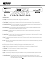
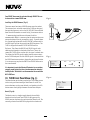
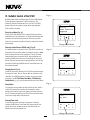
Front Panel Features
1. Standby: This blue LED will light when the T2SIR is plugged into an AC power outlet.
2. Tuner Highlight: This highlight bar shifts between the Tuner A and B display to indicate which Tuner is being controlled.
3. Broadcast Band Display: This line of the front panel display shows the selected broadcast band and frequency or channel. The
bands available are AM, FM and optional SIRIUS.
4. Metadata Display: This line of the display scrolls RDS, Radio Data Service, information for FM and SIRIUS Radio broadcast
information when a SIRIUS-Ready receiver is connected.
5. Preset Number: The T2SIR features up to 5 banks of 20 presets each. This indicates the number of the preset bank of the
selected preset.
6. Antenna Signal: The level of signal level is indicated with up to five bars, five being the best. When listening to FM, full stereo
reception is indicated with an abbreviated ST.
7. Menu: This capacitive touch panel allows front access to the T2SIR’s controls as well as preset listening selections and tuning
parameters.
8. Power: This button turns the power for the front panel off when tapped, and causes a soft reboot of the operating system when
it is held for 3 seconds.
9. A/B: By tapping the A/B button, the highlighted Tuner output and control toggles between A and B.
10. Band: The Band button toggles between AM, FM and SIRIUS when it is activated for the highlighted Tuner A or B.
11. IR Window: The T2SIR will be control via IR through its front panel IR receiver.
12. OK: Ok initiates a highlighted Menu choice.
13. Disp: This button toggles through the tuning choices for SIRIUS. This is only functional when SIRIUS reception is activated.
14. Up and Down Arrows: These arrow buttons provide multiple functions depending on the mode of the Tuner. In normal
operation, they initiate tuning up and down through the selected band. When in menu mode, they scroll
up and down through the menu choices.
4
13

072 8
3033118
R
T
E
E
T
K
N
I
CM
Model N V-T2 SIR
Dual SIRIUS R ead y AM/F M Tuner
www.nu votechnolo gie s.com
NuVo Tec hno logies LLC Hebron, KY USA •
CON FORMS TO U L
STD .6006 5 CERTI FIED
TO CA N/CSA ST D.
C22 .2 No.6 0065: 06
RS 232
SYSTEM
ANTENNA
IN
NuVoNet
USE NV-T2FAA
ANTENNA
IR INPUT
L
AUDIO
R
TUNER A
SIRIUS
L
AUDIO
R
TUNER B
RoHS
SIRIUS
1
4
5
6
7
2
3
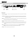
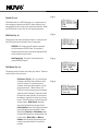
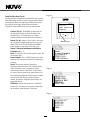
Back Panel Features
1. Antenna Input: This single F connector is the coaxial cable connection between the T2SIR and the included NV-T2FAA AM/FM
antenna.
2. Audio Output: The audio broadcast for AM, FM, or SIRIUS Satellite Radio received by the Tuner module is available through this
stereo RCA output. Tuner A and B offer independent audio outputs for use with the NuVo audio systems or third
party receivers and amplifiers.
3. SIRIUS: This eight-pin connection is a universal SIRIUS communication port. It allows a third party SIRIUS Tuner module to fully
communicate with the Grand Concerto or Essentia E6G NuVoNet Systems.
4. IR Input: The T2SIR offers a single stereo mini, 3.5mm connection for independent IR control of both Tuner A and B.
5. NuVoNet: This single CAT5 connection provides full NuVoNet communication for both Tuners A and B to the NuVo Grand Concerto
and Essentia E6G audio distribution systems. This connection is made at the Grand Concerto EZ Port or the Essentia
E6G Allport.
6. RS232: This DB9 9-pin connector is used for configuration programming (see page 17, V. Using the Tuner Configurator
Software) and bidirectional serial control from a third party home automation controller.
7. AC Power: The T2SIR is designed to plug into any AC power source.
5

1
2
3
4
5
6
7 8
9
0
OK
AM
FM
DAB
SAT
DISP
BAND
PWR
A/B
PRE
T2 Tuner
NV-T2RC4
REMOTE CONTROL
TUNER
1
2
3
4
5
6
7
8
9
10
11
12
13
P
C
P
C
TUNE
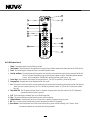
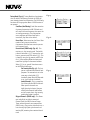
NV-T2RC4 Remote Control
1.Power: The power button turns the Tuner on and off.
2.Tune Buttons: These buttons are the equivalent of using the Up and Down arrows on the front panel of the T2SIR to tune.
3.Band: This button toggles through the Tuner s available broadcast bands.
4.Seek Up and Down: The seek buttons will tune to the next available station with the required signal strength for AM and
FM use. The signal threshold can be adjusted higher or lower using the Tuner Configurator software
(see pg. 18), or through the T2SIR Options menu on the front panel (see pg. 10).
5.Preset Tune: These buttons step through the assigned presets. The T2SIR is capable of 5 banks of 20 presets.
6.Category Tune: Category Tune is not implemented on this model.
7. Pre: This button is used to establish a preset bank and preset number for the frequency being displayed on the selected
Tuner. To tune to a specific preset, push Pre followed by the bank number (1-5) then the 2-digit preset number
(01-20).
8.Tuner A & B LED: This LED glows red when Tuner A is selected and green when Tuner B is selected. This LED glows only
momentarily when a button is pushed.
9.A/B: This button toggles between Tuner A and Tuner B operation.
10.Disp: This button functions only for North American satellite radio use.
11.Numeric Buttons: These buttons (0-9) are used to access a specific station frequency or preset.
12. OK: This is a select button used for saving presets or entering an AM or FM frequency.
13. Band Buttons: These four buttons are a direct select for the tuning bands available through the T2 Tuners. Actual
functionality depends on the model Tuner being controlled.
6

7
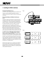
I. Installing the T2SIR in the Home
Connecting the Audio Outputs (Fig. 1)
The T2SIR has two independent audio outputs labeled A and B.
These are standard stereo RCA connections and can be
connected to any device designed to receive an analog stereo
audio signal.
Setting the Audio Outputs for NuVoNet or Standalone use
(Fig. 2)
The outputs A and B are individually set from the front panel
display of the T2SIR. When the Tuner is initially plugged into
an AC power source, a short setup wizard will appear on the
display. A message, Uninitialized State Detected (Press OK)
will appear. When OK is pressed, the prompt is to select a
regional tuning standard. The choices are USA/Canada,
Western Europe, Australia, and New Zealand. Use the Up and
Down arrows to highlight the appropriate choice and touch the
OK button to select this. Once regional tuning has been
selected, the display will prompt for the use of each output A
and B. Using the Up and Down arrows on the front panel, move
the highlight to the appropriate use of the Tuner output and
touch OK. The choices are Stand Alone, Source 1, Source 2,
Source 3, Source 4, Source 5, and Source 6. For any use other
than with the Essentia E6G or Grand Concerto Systems, select
Standalone. This will require IR or serial control of the T2SIR’s
functions. Highlighting the appropriate Source number input
for the NuVo system and touching the OK button sets NuVoNet
communication. Once Output A is set, the highlight will move
to Output B. For operation, both outputs A and B must be set as
Standalone or as a NuVoNet Source.
When the Tuner’s outputs are set, they will return to FM 87.9,
or the minimum FM band setting for the selected regional
tuning parameters. At this point the T2SIR is ready for either
NuVoNet communication or standalone use, depending on the
setting made for both outputs.
ANTENNA
IN
USE N V-T2FAA
ANT ENNA
L
AUDIO
R
TUNER A
SIRIUS
L
AUDIO
R
TUNER B
SIRIUS
SOURCE L INK
L
R
L
R
L
R
SOURCE I NPUT S
TIP =L
RIN G=R
ZONE 2
VARI ABLE
OUT PUT
FIX ED
OUT PUT
TIP =L
RIN G=R
VARI ABLE
OUT PUT
FIX ED
OUT PUT
TIP =L
RIN G=R
VARIA BLE
OUT PUT
FIX ED
OUT PUT
TIP =L
RIN G=R
1 2 3 4 5
6
1 2 3 4 5
6
1 2 3
4
CON NECT TO
NV-I 8X
USE N V-SLC1
CAB LE
5
6
ZON E 1
VARI ABLE
OUT PUT
FIX ED
OUT PUT
SPE AKER
40W /6 OHMS X 2
LEF T RIGHT
ZONE 3
ZON E 4
SOURCE S TATU S
SPE AKER
40W /6 OHMS X 2
LEF T RIGHT
SPE AKER
40W /6 OHMS X 2
LEF T RIGHT
SPE AKER
40W /6 OHMS X 2
LEF T RIGHT
Fig. 1
Fig. 2
MENU
BAND
OK
A/B
DISP
Uninitialized
State Detected
(Press OK)
MENU
BAND
OK
A/B
DISP
Regional Setup
US and Canada
Western Europe
Australia
MENU
BAND
OK
A/B
DISP
Set TunerA Mode
Standalone
Source 1
Source 2

8
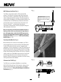
AM/FM Antenna Installation (Fig. 3)
The T2SIR is shipped with the NV-T2FAA active AM/FM
antenna. The antenna is designed to work actively with the
Tuner using standard 75-ohm coaxial cable. Quad-shielded
cable is recommended for this purpose. The advantage of the
active antenna technology is the remote location capability, up
to 200 feet from the T2SIR location, without the need for an
external power supply. The termination at the antenna and
Tuner is a standard F style connector. No software
application or configuration is necessary beyond making the
cable connection at each end.
Note, for best results, the T2FAA antenna should be located as
high as possible, either in an attic or outside. If you choose to
use a third party antenna, other than the T2FAA, you must use
the forced off setting from the menu to allow the signal to pass
through to the T2SIR, (see section III. T2SIR Front Panel Menu,
Antenna Power, pg. 14).
Connecting for NuVoNet Use (Fig. 4)
Once audio outputs A and B are set for NuVoNet, the T2SIR is
ready to communicate in real time with the Grand Concerto or
Essentia E6G audio distribution systems. To complete the
connection, all that is necessary is a single CAT5 cable from the
NuVoNet output on the T2SIR’s back panel to one of the Device
inputs on either the Grand Concerto EZ Port or the Essentia E6G
Allport. Since the outputs of the Tuner must be set as a specific
source number input for NuVoNet communication, the number
of the Device connection used is irrelevant to the system’s
operation. Once the connection is complete, the Tuner is ready
to fully communicate with NuVoNet.
IR Control of the T2SIR (Fig. 5)
The T2SIR can be used without NuVoNet as a standalone
AM/FM/SIRIUS-Ready Tuner. The IR receiver is always active,
however control through IR is typically done in Standalone
mode, (see section I. Setting the Audio Outputs for NuVoNet or
Standalone use, pg. 7).
Fig. 3
Fig. 4
MENU
OK
Jozef Kossovit
SIR
SR 86 (P101)
SIRIUS Pops
3:09 PM
Hungaria
0728
3033 118
E
R
T
E
T
K
N
I
CM
Mod el NV-T2 SIR
Dual S IRIU S Ready AM /FM Tuner
www. nuvote chno logies .com
NuVo Tec hnolog ies LL C Hebr on, KY USA •
CONF ORMS TO UL
STD. 60065 CE RTIF IED
TO CAN/C SA STD.
C22. 2 No.600 65:0 6
RS 23 2
SYSTEM
NuVoN et
IR IN PUT
RoHS
The NuVo active
antenna can be located up
to 200 feet from the T2SIR
Tuner.
ANTEN NA
IN
USE N V-T2FAA
ANT ENNA
L
AUDIO
R
TUNER A
SIRIUS
L
AUDIO
R
TUNER B
SIRIUS

9
Once the audio outputs are set at Standalone, the T2SIR offers
three methods for IR control. One is to take the IR output of
your control device using a mono 3.5mm patch cable plugged
into the Direct IR input on the back panel of the T2SIR. Tuners A
and B feature discrete commands, allowing both Tuners to be
controlled independently from one input. The second method
for IR control is to attach an IR emitter over the IR receiver on
the front panel, and the third method is to aim the remote
control at the IR receiver located on the front panel.
RS232 Serial Control
The T2SIR features a bidirectional DB9 port for serial control.
This enables the Tuner to be controlled via a third party home
automation system and will in turn issue present state
commands back to the controller. Potentially, all aspects of
NuVoNet communication can be emulated using the serial
control capability. The necessary protocol for serial use can be
downloaded from the NuVo website ProZone at
SYS ON
EXT. MUTE
SYSTEM
ZONE TRIGGER OUTP UTS
NETWORK
SUM1
EMITTER OUTPUTS
3033118
C
US
R
CONFORMS TO
UL STD.6500
CERTIFIED TO
CAN/CSA STD.E60065
NuVo Technologies Cincinna ti Ohio U SA
FUSE:T5 A
120V 60Hz 500W
MODEL NV-I8M
SIX SOURCE EIGHT ZONE
AUDIO DISTRIBUTION SYSTEM
www.nuvotechnologie s.com
DIGITAL LINK
VARIABLE
OUTPUT
FIXED
OUTPUT
TIP=L
RING=R
VARIABLE
OUTPUT
FIXED
OUTPUT
TIP=L
RING=R
VAR.
OUT
FIX.
OUT
PROGRAM
1 2 3
4
1 2 3
CONNECT TO
NV-I8X
USE NV-SLC1
CABLE
CONNECT TO
NV-I8EZP1
USE NV-NC1
CABLE
USE CNLY WITH 250V FUSE
4
5
6
SUM2
5 6 7
8
ZONE 5
ZONE 6
ZONE 7
ZONE 8
RS 232
SPEAKER
40W/6 OHMS X 2
LEFT RIGHT
SPEAKER
40W/6 OHMS X 2
LEFT RIGHT
SPEAKER
40W/6 OHMS X 2
LEFT RIGHT
0728
303 3118
R
T
E
E
T
K
N
I
CM
Model NV -T2 SIR
Dual SIRI US Ready AM/FM Tuner
www.nuvot echno logi es.com
NuVo Techno log ies LLC Hebr on, KY USA •
CONFORMS TO UL
STD.60 065 CERTIFIED
TO CAN/CSA STD.
C22.2 No.60 065:0 6
RS 232
SYS TEM
NuVoNet
IR INPUT
RoHS
Fig. 5
Fig. 6
Fig. 7
II. T2SIR Use with SIRIUS Radio
The SIRIUS 8-Pin Connector (Fig. 6)
Each Tuner, A and B, has a SIRIUS-Ready connector on its back
panel. This connector is ready to receive the Tuner signal and
related metadata from a SIRIUS receiver. Any SIRIUS receiver
equipped with the SIRIUS connector will communicate with the
T2SIR’s input. The cable necessary for this connection is
typically supplied with the SIRIUS receiver. Once the 8-pin
connection is made from the SIRIUS receiver to the T2SIR,
SIRIUS will be recognized as a radio band for either Tuner A or
B.
SIRIUS Modules and Subscription (Fig. 7)
There is not a specific SIRIUS receiver that must be used in
conjunction with the T2SIR. Several are on the market, and the
only pre-requisite is that the receiver used has the 8-pin
SIRIUS-Ready connector. NuVo does have the NV-SCH1 home
receiver module as a convenient, inexpensive solution for the
T2SIR. Each SIRIUS Tuner has an ID associated with it. This
number is typically found printed on the SIRIUS Tuner or by
going to the T2SIR SIRIUS Info menu. Each attached SIRIUS
receiver must be activated using its ID number.
ANTENNA
IN
USE NV-T2FAA
ANTENNA
L
AUDIO
R
TUNER A
SIRIUS
L
AUDIO
R
TUNER B
SIRIUS
SIRIUS-Ready 8-pin connectors
ANTEN NA
IN
USE N V-T2FAA
ANT ENNA
L
AUDIO
R
TUNER A
SIRIUS
L
AUDIO
R
TUNER B
SIRIUS
Diagram shown using a NV-SCH1 SIRIUS Home Tuner

10
Your SIRIUS Tuners must be activated through SIRIUS. This can
be done online at www.SIRIUS.com.
Installing the SIRIUS Antenna (Fig. 8)
There are several versions of SIRIUS antennas on the market.
The antennas best suited for use with the T2SIR are designed
for outside placement, such as the NV-SCH-ANT also available
from Directed Electronics as model 14245. An antenna with an
F connector designed for use with coaxial cable is
recommended. Often it is necessary for the antenna to have an
unimpeded view of the sky to receive a signal. Figure 8 shows
this type of application with the NV-SCH-ANT antenna with its
included signal splitter for use with two SIRIUS receivers. The
T2SIR is shipped with two NV-T2FSD AM/FM/Satellite
Diplexers. This allows the AM/FM and SIRIUS signals to be
combined and brought to the back of the Tuner. There, the
second NV-T2FSD can be used to split the signal a second time.
This allows the AM/FM signal to come into the antenna input
on the T2SIR back panel and the SIRIUS signal is then routed to
the SIRIUS receiver or receivers, depending on the application.
It is not necessary to place the AM/FM and SIRIUS antennas in
the same location.
It is important to note that Directed Electronics has an outdoor
antenna, model 14240, that has a 50 ohm connection intended
for RG58 cable. This model is not recommended for use with the
NV-T2SIR Tuner.
III. T2SIR Front Panel Menu (Fig. 9)
The Menu button on the front panel of the T2SIR allows access
to the tuning and functionality of both Tuners A and B. The
menu selections are the same for both, and touching the A/B
button moves the highlight between the two Tuner outputs.
Bands (Fig. 10)
The Bands menu is a simple toggle through the available
broadcast bands of each Tuner. SIRIUS is only present if a
SIRIUS receiver has been plugged into either Tuner A or B. The
currently selected band will be displayed with a check mark.
MENU
BAND
OK
A/B
DISP
Main Menu
Bands
Channels
My Presets 1
Fig. 9
Fig. 8
Fig. 10
Main Menu
FM
AM
SIRIUS
IN
OUT1 OUT2
MODEL SRS-2V8
2300-2400 MHZ

11
SIRIUS Info (Fig. 12)
There are two sub-menus within this choice. It is only active if
the SIRIUS input for the selected Tuner is being used.
SIRIUS ID: This displays the ID number associated
with the connected SIRIUS Tuner. This number is
referenced when activating the Tuner through SIRIUS,
or for customer service issues.
Now Playing Info: This scrolls the metadata for a
selected SIRIUS Channel.
T2SIR Options (Fig. 13)
The options menu has three main tuning sub-menus. These are
tuning defaults that can be set:
Edit Presets (Fig. 14): This is a great tool for
allowing a currently selected channel to be
saved as a preset. As a number preset is
selected, the display will prompt to Assign
to current channel . When selected, the
T2SIR will save the frequency and associated
short name of the channel. There are 5 banks
of 20 presets each available. To add a preset
to favorites, highlight and select an existing
preset. This will bring up a second menu with
several choices: Delete Preset, which will
erase the highlighted preset from the list;
Add to Favorites places the highlighted preset
into the Favorites menu available at each
Control Pad; Move Up and Move Down moves
the highlighted preset up or down within the
list of presets; Move to Top and Move to
Bottom places the highlighted preset in the
number 1 position or to the last available
position.
T2SIR Options
Edit Presets
Seek Tune
Tuning Mode
Fig. 12
Fig. 13
Fig. 14
SIRIUS Info
SIRIUS ID
Now Playing I..
Edit Presets
Delete Preset
Add to Favori...
Move Up
Channels (Fig. 11)
The Channel menu is a SIRIUS function. It is a quick access to
the categories associated with SIRIUS. When selected, each
category will expand to display the associated channels. When
the SIRIUS input is not in use, this will appear grayed out.
Fig. 11
Channels
All SIRIUS Cha
Pop
Rock

12
Tuning Mode (Fig. 15): Tuning Mode has four choices
that set defaults for the way in which the T2SIR will
tune through channels or frequencies. The SIRIUS only
functions will be grayed out when a SIRIUS receiver is
not present.
Seek Tune (Am/FM only): Seek Tune searches
for strong frequencies in AM/FM bands and
will stop at the next frequency that meets the
set tuning parameters. This menu option
turns seek on or off. When Seek Tune is
turned off, Step Tune is the default.
Preset Tune: When turned on, the Preset Tune
mode will only stop at channels or
frequencies that have been saved as presets
in the current band.
Parental Lock (SIRIUS only) (Fig. 16): This
requires a 4-digit security code. The default
parental lock code is 5555. To access the sub-
menus, you must enter the default 5555. This
is done by using the Up arrow to scroll to the
first 5, then touching OK on the front panel
moves the highlight to the second number.
When 5555 is set, you will then have access
to the Parental Lock setup.
Set Security Code (Fig. 17): This lets
you set a new code for Parental Lock
purposes. The new code is set in the
same way as the default 5555
described above. Once the new code
is set, it will replace the default.
Locked Channels: This is a complete
list of the available SIRIUS channels.
When specific channels are
highlighted and selected, they are
added to the Parental Lock feature
and will require the 4-digit security
code before audio is enabled.
Skipped Channels (SIRIUS only): This allows
you to highlight and select unwanted
channels from the SIRIUS channel lineup.
These selected channels are removed from
SIRIUS tuning. They can be added back in at a
later date by highlighting the channel and
touching OK, removing the associated check
mark.
Fig. 15
Fig. 16
Fig. 17
Tuning Mode
Seek Tune
Preset Tune
Lock Code? [9]
5555
Parental Lock
Set Security..
Lock Channel...
Set Lock [9]
0000

13
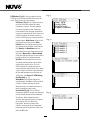
T2SIR Settings (Fig. 18)
There are several operational defaults that are set in this menu
choice:
Operating Mode (Fig. 19): This will display the set
choice for each Tuner output A and B with a check
mark. The choices are Standalone, Source 1, Source 2,
Source 3, Source 4, Source 5, and Source 6. Here, the
source number or standalone can be changed from the
initial power on setting. Unavailable NuVoNet sources
will be grayed out.
Enabled Bands: Broadcast bands associated with each
Tuner can be turned off here. This is useful especially
for AM where an acceptable AM signal is not possible.
If SIRIUS is disabled, all SIRIUS related menu items
will be removed as opposed just being grayed out.
Tuning: There are four sub-menus that set default
tuning parameters for the T2SIR:
Fine Tuning: This reduces the frequency step
to 50 kHz in FM and 1 kHz in AM. With today’s
digital Tuners, this feature is rarely used.
Regional Setup: Regional Setup sets the
default tuning standard for four regions of
the world. The choices are US/Canada,
Western Europe, Australia, and New Zealand.
Custom is grayed out. This must be set using
the Configurator Software discussed later in
this manual.
Seek Thresholds (Fig. 20): The recognized
signal level for AM and FM can be set in this
menu. There are three default levels with 1
being the lowest, requiring a stronger signal
to be recognized and 3 being the highest,
requiring a weak to moderate signal to be
recognized. The default is 2, the middle level.
Brightness: Brightness sets the overall level
of the display. There are seven degrees of
brightness to choose from.
Fig. 18
Fig. 19
Fig. 20
T2SIR Settings
Operating Mod
Enabled Bands
Tuning
Operating Mode
Tuner A
Tuner B
Set Tuner A Mo
Standalone
Source 1
Source 2
Seek Thresholds
AM Threshold
FM Threshold
AM Threshold
Level 1
Level 2
Level 3

14
Antenna Power: The choices here are
Automatic, Forced ON and Forced OFF.
Automatic is the default and allows the T2SIR
to recognize a present SIRIUS receiver. In
Automatic the T2SIR lets the attached SIRIUS
receiver supply the 5 volts to both the SIRIUS
and T2FAA antennas. In instances where you
intend on using a third party FM antenna, the
Forced OFF choice is necessary to block DC
voltage needed for AM reception. Forced ON
supplies DC voltage for AM reception in the
presence of a SIRIUS receiver which is not
sharing an antenna cable with the NV-T2FAA
antenna.
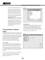
Diagnostics (Fig. 21): Signal strength for AM, FM and
SIRIUS reception and the current firmware version
number are provided in the Diagnostics menu.
Version: This displays the T2SIR’s current
firmware version. Upgraded versions are
posted on the NuVo website ProZone and are
loaded onto the Tuner by downloading a new
configuration from the Tuner Configurator
software through the RS232 port.
AM/FM Signal Strength (Fig. 22): This
displays two levels for Tuners A and B. RSSI,
received signal strength indicator, is a
measurement in dBuV, and SNR, signal to
noise is measured in dB.
SIRIUS Signal Strength (Fig. 23): Three
separate measurements are provided in
levels 1-4, None, Weak, Good, or Strong. The
measurements are SAT (satellite), TERR
(terrestrial), and COMBINED.
Audio Test: The test tone is intended to verify an
audio signal from an attached SIRIUS receiver. The
tone will continue until you tune up or down, or
change broadcast bands.
Reset Memory (Fig. 24): This should be used only
when it is advantageous to remove all settings from
the Tuner. Choosing yes to reset memory returns the
T2SIR to its factory default.
Fig. 21
Fig. 22
Fig. 23
Fig. 24
Diagnostics
Version
Signal Streng..
Audio Test
AM/FM Strength
RSSI: 60 dBuV
SNR: 31 dB
SIRIUS Strength
SAT: Strong
TERR: None
Combined: Strong
Are You Sure?
No
Yes
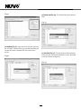
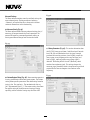
La page charge ...
La page charge ...
La page charge ...
La page charge ...
La page charge ...
La page charge ...
La page charge ...
La page charge ...
La page charge ...
La page charge ...
La page charge ...
La page charge ...
-
 1
1
-
 2
2
-
 3
3
-
 4
4
-
 5
5
-
 6
6
-
 7
7
-
 8
8
-
 9
9
-
 10
10
-
 11
11
-
 12
12
-
 13
13
-
 14
14
-
 15
15
-
 16
16
-
 17
17
-
 18
18
-
 19
19
-
 20
20
-
 21
21
-
 22
22
-
 23
23
-
 24
24
-
 25
25
-
 26
26
-
 27
27
-
 28
28
-
 29
29
-
 30
30
-
 31
31
-
 32
32


Documents connexes
-
Nuvo Music port and music port elite Guide d'installation
-
-
-
-
Nuvo Essentia BTicino NV-E6DXS-BT Guide d'installation
-
Nuvo Concerto NV-I8DMS Manuel utilisateur
-
-
-
-