
Thank you for buying RAB lighting xtures. Our goal is to design the best quality products to get the job done right. We’d like to hear your comments.
Call the Marketing Department at 888-RAB-1000 or email: marketing@rabweb.com
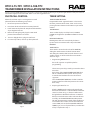
RTX12-75-TPC / RTX12-100-TPC
TRANSFORMER INSTALLATION INSTRUCTIONS
IMPORTANT
READ CAREFULLY BEFORE INSTALLING TRANSFORMER. RETAIN THESE INSTRUCTIONS FOR FUTURE REFERENCE.
RTX12-75-TPC / RTX12-100-TPC
has an input of 120VAC 60Hz 0.7A. Transformer comes with a swivel photocell and timer. RAB
transformer must be wired in accordance with the National Electrical Code and all applicable local codes. Proper grounding
is required for safety. THIS PRODUCT MUST BE INSTALLED IN ACCORDANCE WITH THE APPLICABLE INSTALLATION CODE BY A
PERSON FAMILIAR WITH THE CONSTRUCTION AND OPERATION OF THE PRODUCT AND THE HAZARDS INVOLVED.
WARNING: Make certain power is OFF before installing or maintaining xtures.
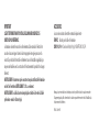
SAFETY INSTRUCTIONS
WARNING – Risk of Electric Shock. Install power unit 5 feet (1.5 m) or more from a pool, spa, or fountain. Where the power
unit is installed indoors within 10 feet (3.0 m) of a pool, spa, or fountain.
Not to use an extension cord.
“CAUTION” FOR USE ONLY ON A BRANCH CIRCUIT PROTECTED BY A CLASS A TYPE GROUND FAULT CIRCUIT INTERRUPTER.
FOR USE WITH LANDSCAPE LIGHTING SYSTEMS ONLY.
THIS DEVICE IS ACCEPTED AS A COMPONENT OF LANDSCAPE LIGHTING SYSTEM WHERE THE SUITABILITY OF THE
COMBINATION SHALL BE DETERMINED BY THE LOCAL INSPECTION AUTHORITIES HAVING JURISDICTION.
DO NOT CONNECT TWO OR MORE POWER SUPPLIES IN PARALLEL.
DO NOT MOUNT TRANSFORMER WITHIN 10 feet (3.0 m) OF A SWIMMING POOL OR SPA.
RISK OF FIRE. DO NOT PLACE INSULATION UNDER TERMINAL PLATE. CHECK CONNECTION AFTER INSTALLATION.
THE POWER UNIT SHALL BE CONNECTED TO A GFCI PROTECTED HOODED FLUSH TYPE COVER PLATE RECEPTACLE
MARKED “WET LOCATION” WHILE IN USE.”
FOR USE ONLY WITH LOW VOLTAGE LANDSCAPE LUMINAIRES AND FITTINGS.

Thank you for buying RAB lighting xtures. Our goal is to design the best quality products to get the job done right. We’d like to hear your comments.
Call the Marketing Department at 888-RAB-1000 or email: marketing@rabweb.com
RTX12-75-TPC / RTX12-100-TPC
TRANSFORMER INSTALLATION INSTRUCTIONS
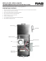
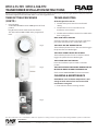
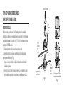
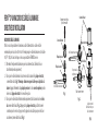
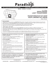
FEATURES AND CONTROLS
1. Fully enclosed Stainless steel housing with removable cover for easy access of controls and connections.
2. Integral mounting bracket for extra strength.
3. Epoxy encapsulated transformer for weather protection.
4. Inline secondary breaker for overload protection.
5. Multiple voltage taps 12V, 13V, 14V, & 15V
6. Industry standard Knockouts.
7. User congurable, Programmable timer and Swivel photocell
8. Non detachable 5 foot power cord.
Shorting Plug
Timer
Photocell Connection
Timer Switch
ON/OFF Circuit Breaker
Stainless Housing
Multiple Voltage
Output Terminal
Photocell Sensor
Fig. 1

Thank you for buying RAB lighting xtures. Our goal is to design the best quality products to get the job done right. We’d like to hear your comments.
Call the Marketing Department at 888-RAB-1000 or email: marketing@rabweb.com
RTX12-75-TPC / RTX12-100-TPC
TRANSFORMER INSTALLATION INSTRUCTIONS
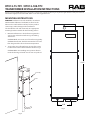
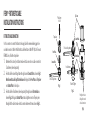
MOUNTING INSTRUCTIONS
WARNING: Transformers must be installed in accordance
with the National Electrical Code (NEC) and local codes.
Failure to do so will void the warranty and may result in
serious injury and/or damage to the transformer.
The Transformer is for wall mount only. Use appropriate
mounting hardware suitable for the mounting surface.
1. Mount transformer to a solid surface using stainless
steel screws and anchors. Refer to Fig 3. for drilling
dimensions.
CAUTION: Make sure screws are of a load bearing quality.
CAUTION: Transformer should be mounted at least 1.5 ft
from the ground for safe and convenient operation.
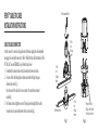
2. To open the cover of Transformer, unscrew four screws
located on the sides of the transformer shown in Fig. 2.
CAUTION: When reassembling cover, position all wires
inside the housing and make sure no wires are pinched.
13.57
2.50
SCALE 0.400
Screw (4)
Cover
Fig. 2
Fig. 3

Thank you for buying RAB lighting xtures. Our goal is to design the best quality products to get the job done right. We’d like to hear your comments.
Call the Marketing Department at 888-RAB-1000 or email: marketing@rabweb.com
RTX12-75-TPC / RTX12-100-TPC
TRANSFORMER INSTALLATION INSTRUCTIONS
TRANSFORMER SIZING
There are two transformers oered, 75W and 100W
The total lamp wattage of all xtures connected to one
transformer must not exceed 80% of the transformer
wattage capacity. To determine the total number of xture
that can be connected to the transformer, follow the formula
below.
75W Transformer: Maximum available Wattage = 60 Watt
100W Transformer: Maximum available Wattage = 80 Watt
For example:
If 5W xtured are used, only 12 xtures can be used with
75W Transformer and 16 xtures can be used with 100W
Transformer.
LOW VOLTAGE CABLE LENGTH
Low voltage cable is available in #16-2GA in multiples of
100ft.
Recommended Voltage Drop should be less than 1.5
volts. Calculate the maximum cable length using the
formula:
Voltage Drop (Volts) = Total Power for xtures on Cable
(Watts) x Length of run (Feet) x 2
Cable Size Constant
Cable Size Constant for 16AWG is 2200.
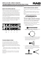
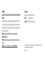
MULTITAP INSTALLATION
Multi-Tap transformers supply output voltage which exceeds
12 Volts. The transformer supplies output voltages of 12,
13, 14, and 15 Volts. Extreme care must be taken during
installation to avoid xture burnout due to high voltage. Use
of a voltmeter during installation is the only way to ensure
a proper voltage at the xture. Multi-tap on the transformer
can be used to correct voltage drop. Make sure the voltage
test is within ±1.5V of 12V.
Connect one side of xtures (common) up to 75/ 100 watts
per circuit, using 16 AWG or larger direct burial cable. Strip
3/4” of cable insulation and twist wire strands tightly before
insertion into transformer’s output terminals. Tighten
connector screws rmly.
12 VOLT
0
0 VOLT
(nominal)
13 VOLT
14 VOLT
15 VOLT
12 VOLT CABLE LAYOUT OPTIONS
Connect one side of each lamp to COMMON terminal
and the other side to 12V-15V terminal as needed.
CAUTION: Measure the closest and furthest xture to
ensure the voltage test is within ±1.5V of 12V.
1. Straight run installation - Fixtures run in sequence
directly from the transformer.
2. Loop installation - Fixtures are arranged in a looped
circuit, reducing the eects of voltage drop.
3. Hub load installation or multiple cable run - Fixtures
run in two or more directions from the transformer.
Locating the transformer in the center of the run
reduces the eects of voltage drop.
4. ‘T’ installation - Allows more equal distribution of
power to the center of the run, or to a run some
distance away. Cable running from the transformer
must be of a heavier guage.
T
CIRCUIT 1
3
00W
CIRCUIT 2
300W
CIRCUIT 3
300W
CIRCUIT 1
3
00W
CIRCUIT 2
300W
CIRCUIT 3
300W
OF LOAD
OF LOAD
COM 12V
COM 12V COM 12V
T
300W
300W
3
NOT
USED
COM 12V COM 12V
NOT
USED
T
T
T
T
T
T
T

Thank you for buying RAB lighting xtures. Our goal is to design the best quality products to get the job done right. We’d like to hear your comments.
Call the Marketing Department at 888-RAB-1000 or email: marketing@rabweb.com
RTX12-75-TPC / RTX12-100-TPC
TRANSFORMER INSTALLATION INSTRUCTIONS
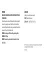
PHOTOCELL CONTROL
Photocell and Timer may be used together. To install
photocell, follow the following steps below:
1. Disconnect power to transformer.
2. Knock out side knock out hole to mount photocell.
3. Install 120V swivel photocell. Aim photocell toward the
sky and tighten lock nut.
4. Remove Shorting Plug and plug the 120V swivel
photocell to transformer enclosure.
5. To test in daylight hours, plug in Transformer.
6. For normal operation, remove cap from photocell.
TIMER SETTING
TIMER SEGMENT BUTTONS:
Programmable timer segment buttons are located in
the outer perimeter of the Timer. Timer can be set by
pressing the timer buttons. Each buttons represents 30
minutes.
TIME READOUT:
Timer readout displays each day hours (6:30AM to
6:30PM) and night hours (6:30PM to 6:30AM are shown
Fig. 5).
ROTATING TIMER DIAL:
Rotating timer dial can be turned only clockwise.
It points to the current time of the day on the TIME
READOUT.
TIMER SWITCH:
Timer switch is located on the side of the TIMER. By
sliding the switch to timer clock will activate timer
and sliding the switch to “ON” overrides the timer and
enables normal use of the outlet. The timer switch is
shown on Fig. 6.
1. Programming ON/OFF times
Ensure all segments are pulled up before
programming.
Select a time period (or periods) you want the device
turned on.
Push down all the TIMER SEGMENT BUTTONS that
fall on or within that time period. You may need
to turn the dial clockwise to access the desired
segments.
Turn the ROTATING TIMER DIAL clockwise until the
pointer on the face of the dial points to the current
time of day.
2. Preparing the timer for use
Plug the TIMER into the outlet on the transformer.
Ensure the transformer is switched ON for automatic
control as shown in Fig. 7. (The timer will not turn
the light xtures ON if the transformer is switched
OFF.) To override the timer and use the transformer
normally, set the MASTER SWITCH to ON position.
This will deactivate timer control of the transformer.
To reactivate timer control, ensure the transformer
is turned ON, and set the timer MASTER SWITCH to
TIMER (Fig. 6). In case of power failure, reset the time
of day as explained in step 1.
Fig. 4

Thank you for buying RAB lighting xtures. Our goal is to design the best quality products to get the job done right. We’d like to hear your comments.
Call the Marketing Department at 888-RAB-1000 or email: marketing@rabweb.com
RTX12-75-TPC / RTX12-100-TPC
TRANSFORMER INSTALLATION INSTRUCTIONS
TIMER SETTING PROCEDURE
CONTD.
1. Using the timer
Set the MASTER SWITCH to the TIMER (picture of clock)
position.
Plug the timer into the outlet on the transformer.
The device will turn ON and OFF at the programmed
times.
TROUBLESHOOTING
All of the lights fail to turn on
1. Check that the power switch is not in the OFF
setting.
2. Check if there is a loose connection at the
transfomer screw terminal.
3. Check that the transformer outlet is live and that the
timer is plugged in.
ONLY SOME LIGHTS TURN ON
Check the connectors to make sure the wire stabs have
pierced the transformer wire and the xture wire.
THE LIGHTS ARE “ON” DURING THE DAY
The transformer photocell is in a dark area which triggers
the photocell to turn ON the lights.
THE LIGHTS DO NOT SWITCH “ON” AT DUSK.
The transformer photocell is not in a dark area which
triggers the photocell to turn ON the lights.
THE FIXTURE DOES NOT TURN ON
Ensure the transformer power switch is in the ON
position.
THE LIGHT FIXTURES TURN ON/OFF DURING THE DAY
INSTEAD OF NIGHT OR NIGHT INSTEAD OF DAY
Check section TIMER CONTROL for timer instructions.
CLEANING & MAINTENANCE
CAUTION: Be sure transformer temperature is cool
enough to touch. Do not clean or maintain while
transformer is energized.
1. Clean with non-abrasive cleaning solution.
Note: These instructions do not cover all details or variations in equipment nor do they provide for every possible situation during installation operation or maintenance.
Easy Answers
rabweb.com
Visit our website for product info
Tech Help Line
Call our experts - 888 722-1000
e-mail
Answered promptly - sales@rabweb.com
Free Lighting Layouts
Answered online or by request
©
2017 RAB LIGHTING Inc.
Northvale, New Jersey 07647 USA
RTX12-XX-TPC IN 0317
Fig. 5
Fig. 6
Fig. 7

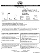
FERN CABLE TO CABLE
INSTALLATION INSTRUCTIONS
TM
CABLE TO CABLE CONNECTOR
Use this connector to extend or change direction of the main supply cable. Recommended
wire guage to be used with connector is 18GA or 16GA. Note that cable from xture is 18GA
SPT-1W, 2.3A. To mount FERNCCC series, follow the steps below -
1. Determine the location to make electrical connection between two cables.
2. Feed one of the cable through lower channel and another through the upper
channel as shown in Fig. 1.
Note - One end of the cable has to be connected to the transformer (ordered
separately).
3. Push down, rotate and tighten connector. The pins pierce through both the cables
to make electrical connection between the two as shown in Fig. 2.
Push down and Rotate
From Transformer
To the
Low
Voltage
xture
Fig. 1
Pins pierce the Low
Voltage cable to make
electrical connections
Fig. 2
To the
Low
Voltage
xture
To the
Low
Voltage
xture

ACCESSORIES
Following accessories should be ordered separately -
FERNFCC Fixture to Cable Connector
CORD16/12V-100 16GA SPT-2W 12V 3.7A 100FT cord
Note: These instructions do not cover all details or variations in equipment nor do they provide for every possible
situation during installation operation or maintenance.
FERNCCC IN 0916
IMPORTANT
READ CAREFULLY BEFORE INSTALLING FIXTURE. RETAIN THESE INSTRUCTIONS FOR
FUTURE REFERENCE.
Fixtures must be wired in accordance with the National Electrical Code and all applicable
local codes. Proper grounding is required for safety. This product must be installed in
accordance with the applicable installation code by a person familiar with the construction
and operation of the product and the hazards involved.
WARNING: Make certain power is OFF before installing or maintaining xture.
WARNING: MAX 12VAC only.
WARNING: The main low voltage cable is intended for shallow burial - less than 6
inches (152 mm).

Pousser et faire tourner
En provenance du
transformateur
Vers le
luminaire
basse
tension
Fig. 1
Les 4 tigers percent le câble basse
tension pour faire le branchement.
Fig. 2
Vers le
luminaire
basse
tension
Vers le
luminaire
basse
tension
RACCORD DE CÂBLES
Utilisez ce raccord pour allonger un câble d’alimentation principal ou en modier
l’orientation. Le calibre de câble recommandé pour le raccord est de 18 ou 16. À remarquer
que le câble des luminaires est de calibre 18, SPT - 1 W, 2,3 A. Suivez les étapes ci-dessous
pour installer le FERNCCC en série.
1. Déterminez l’endroit où se fera le branchement des deux câbles.
2. Faites passer l’un des câbles dans le canal inférieur, puis l’autre dans le canal
supérieur, comme illustré dans la Fig. 1.
Remarque - L’une des extrémités du câble doit être branchée au transformateur
(commandé séparément).
3. Poussez sur le raccord, faites-le tourner, puis serrez-le. Les tiges percent les gaines
des deux câbles pour procéder à leur raccordement, comme illustré dans la Fig. 2.
FERN D’UN RACCORD DE CÂBLES
DIRECTIVES D’INSTALLATION
TM

ACCESSORIES
Les accessoires suivants doivent être commandés séparément -
FERNFCC Raccord pour le câble et le luminaire
CORD16/12V-100 Cordon de 30,8 m (100 pi), 16 GA SPT-2 W 12 V 3,7 A
Remarque : Les présentes directives n’abordent pas toutes les possibilités ni toutes les variations en matière
d’équipement pas plus qu’elles donnent toutes les situations pouvant être rencontrées lors de l’installation, du
fonctionnement et de l’entretien.
FERNCCC IN 0916 FR
IMPORTANT
LISEZ ATTENTIVEMENT AVANT D’INSTALLER LE LUMINAIRE CONSERVEZ CES
DIRECTIVES POUR RÉFÉRENCE.
Les luminaires doivent être raccordés conformément au Code national de l’électricité et
aux codes locaux en vigueur. Une mise à la terre appropriée est exigée pour assurer la
sécurité. Ce produit doit être installé conformément au code d’installation applicable, par
une personne familière avec la construction et le fonctionnement du produit et les dangers
inhérents.
AVERTISSEMENT - Assurez-vous que le courant est coupé avant d’installer le luminaire
ou d’en faire l’entretien. AVERTISSEMENT : 12 V c.a. seulement.
AVERTISSEMENT : Le câble à basse tension principal est destiné à être enfoui à faible
profondeur - moins de 152 mm (6 po).

FERN FIXTURE TO CABLE
INSTALLATION INSTRUCTIONS
TM
FIXTURE TO CABLE CONNECTOR
Use this connector to connect the xtures to the supply cable. Recommended wire gauge to be
used with connector is 18GA or 16GA. Note that cable from xture is 18GA SPT-1W, 2.3A. To mount
FERNFCC series, follow the steps below -
1. Determine the location of your xture to make electrical connection on a cable connected to
a Transformer (ordered separately).
2. Feed the cable from Low Voltage xture through channel in Contact Plate as shown in Fig. 1.
Note: Ensure that cable lays at in the channel. Firmly push the Press Plate and Top Cover
onto Contact Plate to lock in place.
3. Feed the cable from Transformer (ordered separately) through channel in Bottom Base as
shown in Fig. 2. Push against Contact Plate, rotate and tighten connector. The pins pierce
through both the cables to make electrical connection between the two as shown in Fig. 3.
Fig. 1
Pins (4) pierce the Low
Voltage cable to make
electrical connections
Fig. 3
Top Cover
Bottom Base
Press Plate
Contact Plate
To the Low Voltage xture
Top Cover
To the Low Voltage xture
From Transformer
Rotate & Tighten
Push down
to lock
Fig. 2
Contact Plate

ACCESSORIES
Following accessories should be ordered separately -
FERNCCC Cable to Cable Connector
CORD16/12V-100 16GA SPT-2W 12V 3.7A 100FT cord
Note: These instructions do not cover all details or variations in equipment nor do they provide for every possible
situation during installation operation or maintenance.
FERNFCC IN 0217
IMPORTANT
READ CAREFULLY BEFORE INSTALLING FIXTURE. RETAIN THESE INSTRUCTIONS FOR FUTURE
REFERENCE.
Fixtures must be wired in accordance with the National Electrical Code and all applicable local
codes. Proper grounding is required for safety. This product must be installed in accordance with
the applicable installation code by a person familiar with the construction and operation of the
product and the hazards involved.
WARNING: Make certain power is OFF before installing or maintaining xture.
WARNING: MAX 12VAC only.
WARNING: The main low voltage cable is intended for shallow burial - less than 6 inches
(152 mm).
WARNING: If a tool is used to tighten the connector, DO NOT OVERTIGHTEN.

RACCORD DE CÂBLE À LUMINAIRE
Utilisez ce raccord pour bancher les luminaires au câble d’alimentation. Le calibre de câble
recommandé pour le raccord est de 18 ou 16. À remarquer que le câble des luminaires est de calibre
18, SPT - 1 W, 2,3 A. Suivez les étapes ci-dessous pour installer le FERNFCC en série.
1. Déterminez l’emplacement du luminaire pour le raccordement à un câble branché à un
transformateur (vendu séparément).
2. Faites passer le câble du luminaire à basse tension dans la rainure del la plaque de contact,
comme illustré dans la Fig. 1. Remarque : Assurez-vous que le câble repose à plat dans la
rainure. Appuyez fermement sur la plaque de pression et sur le couvercle supérieur pour les
insérer sur la plaque de contact et les verrouiller en place.
3. Faites passer le câble du transformateur (vendu séparément) dans la rainure dans le socle du
bas comme illustré dans la Fig. 2. Appuyez sur la plaque de contact, puis faites tourner le
connecteur pour le serrer. Les tiges percent les gaines des deux câbles pour procéder à leur
raccordement, comme illustré dans la Fig 3.
FERN D’UN RACCORD DE CÂBLE À LUMINAIRE
DIRECTIVES D’INSTALLATION
TM
Fig. 1
Les 4 tigers percent le
câble basse tension pour
faire le branchement
Fig. 3
Couvercle du haut
Socle du bas
Plaque de pression
Plaque de contact
Vers le luminaire basse tension
Couvercle du haut
Vers le luminaire basse tension
En provenance du
transformateur
Faites tourner et serrer
Appuyez ensuite dessus
pour le verrouiller
Fig. 2
Plaque de contact

FERNFCC IN 0217 FR
ACCESSORIES
Les accessoires suivants doivent être commandés séparément -
FERNCCC Raccord des câbles
CORD16/12V-100 Cordon de 30,8 m (100 pi), 16 GA SPT-2 W 12 V 3,7 A
Remarque : Les présentes directives n’abordent pas toutes les possibilités ni toutes les variations en matière
d’équipement pas plus qu’elles donnent toutes les situations pouvant être rencontrées lors de l’installation, du
fonctionnement et de l’entretien.
IMPORTANT
LISEZ ATTENTIVEMENT AVANT D’INSTALLER LE LUMINAIRE CONSERVEZ CES DIRECTIVES
POUR RÉFÉRENCE.
Les luminaires doivent être raccordés conformément au Code national de l’électricité et aux codes
locaux en vigueur. Une mise à la terre appropriée est exigée pour assurer la sécurité. Ce produit
doit être installé conformément au code d’installation applicable, par une personne familière
avec la construction et le fonctionnement du produit et les dangers inhérents.
AVERTISSEMENT - Assurez-vous que le courant est coupé avant d’installer le luminaire ou
d’en faire l’entretien. AVERTISSEMENT : 12 V c.a. seulement.
AVERTISSEMENT : Le câble à basse tension principal est destiné à être enfoui à faible
profondeur - moins de 152 mm (6 po).
AVERTISSEMENT : Lorsque vous utilisez un outil pour serrer le connecteur, ÉVITEZ DE TROP
LE SERRER.
-
 1
1
-
 2
2
-
 3
3
-
 4
4
-
 5
5
-
 6
6
-
 7
7
-
 8
8
-
 9
9
-
 10
10
-
 11
11
-
 12
12
-
 13
13
-
 14
14


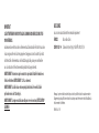
dans d''autres langues
Documents connexes
Autres documents
-
 Hampton Bay HD33678BK Guide d'installation
-
 Hampton Bay HD22007 Mode d'emploi
-
 Sterno Home GL33300 Manuel utilisateur
-
 Hampton Bay HD22772 Guide d'installation
-
 Hampton Bay HD22105BK Mode d'emploi
-
 Hampton Bay HD33970BK Guide d'installation
-
 Hampton Bay HD22928BK Guide d'installation
-
 Hampton Bay HDC33943BK Guide d'installation
-
 Sterno Home GL33600 Guide d'installation
-
 Sterno Home GL33200 Manuel utilisateur


