Asco Series 453 PES Cylinders Le manuel du propriétaire
- Taper
- Le manuel du propriétaire

TK
ZJ +
XV
A
Mise en service - Installation - Inbetriebnahme
TOURILLON MALE MT4 sur VERINS PES A TUBE PROFILÉ
MT4 CENTRE TRUNNION on PES CYLINDERS WITH PROFILED BARREL
MITTELSCHWENKBEFESTIGUNG MT4 AUF PROFILZYLINDER TYPE PES
FR
GB
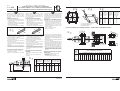
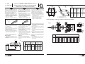
La fi xation par tourillon MT4 permet un mon-
tage oscillant. Ce tourillon coulisse le long du
tube pour permettre le réglage en position
sur site. A cet effet, il est livré non bloqué
sur le tube.
Fitting the MT4 centre trunnion on PES
cylinders allows a choice of position. The
centre trunnion slides along the barrel to al-
low on-site adjustment. For that reason, it is
delivered unlocked.
1- S'assurer que les axes du tourillon sont cor-
rectement orientés par rapport aux orifi ces
du vérin (voir fi g.1)
• Orientation standard: axe du tourillon
perpendiculaire aux orifi ces d'alimentation
du vérin (code 410 002)
•
L'autre position, sur demande: code 410 003
SERRAGE DU TOURILLON
LOCKING THE CENTRE TRUNNION
1- Check that the axes of the spindle are cor-
rectly adjusted in relation to the cylinder
orifi ces (see fi g.1).
• Standard position:the axis of the centre
trunnion is perpendicular to the supply ports
of the cylinder (code 410 002).
•
Optional position, on request: code 410003
C = + Course C = + Stroke C = + Hub
Fig.
Abb
2-Adjust the centre trunnion to the desired
position
over the barrel (see min. and max. values
for cylinder with or without position
detector, following fi gure and table 2).
3- Slightly tighten crosswise the 8 locking
screws following fi gure 3.
4- Unscrew a locking screw on each side of
the centre trunnion (see fi g. 4).
5-Pierce the two free holes on the trunnion
with a drill in accordance with the specifi -
cations in table 5.
6- Re-insert the two locking screws and tighten
the trunnion to the barrel so as to ensure a
perfect tight fi t between the barrel and the
fastening.
MOUNTING SUPPORTS FOR CENTRE
TRUNNION
-
The supports enable mounting according
to
fi g. 6 .
- Grease the axes of the spindle before
mounting.
2-Positionner le tourillon à l'emplacement
souhaité sur le tube (voir valeur mini et
maxi, pour vérin avec ou sans détecteur de
position suivant fi g. et tableau 2)
3- Serrer modérement et en croix, les 8 vis
pointeaux suivant fi g. 3
4- Desserrer une vis pointeau de chaque face
du tourillon (voir fi g.4)
5- Percer à travers les 2 trous libres du tou-
rillon avec un foret suivant spécifi cations du
tableau 5
6- Réintroduire les 2 vis pointeaux pour venir
tarauder le tube de façon à assurer un
blocage parfait entre le tube et la fi xation
- Les supports de tourillon permettant
l'adaptati
on suivant fi g. 6
-
Graisser les axes du tourillon lors du montage.
ADAPTATION SUPPORTS TOURILLON
Die Montage der Mittelschwenkbefestigung MT4
ermöglicht eine bewegliche Befestigung. Die
Schwenkbefestigung kann entlang des Rohres für
eine Positionierung vor Ort verschoben werden.
Deshalb wird sie bei Lieferung nicht fest auf dem
Rohr angezogen.
1- Vergewissern Sie sich, daß die Achsen der
Schwenkbefestigung richtig zu den Zylinderan-
schlüssen hin orientiert sind (siehe Abb. 1).
• Standardpositionierung: Die Achse der
Schwenkbefestigung ist senkrecht zu den
Anschlüssen des Zylinders ausgerichtet (Be-
stell-code 410 002).
• Andere Position auf Anfrage:
Bestell-Code 410 003
ANZIEHEN DER SCHWENKBEFESTIGUNG
MONTAGE DER LAGER FÜR DIE SCHWENK-
BEFESTIGUNG
- Die Stützen ermöglichen eine Montage
gemäß Abb. 6.
- Schmieren Sie die Achsen der
Schwenkbefestigung bei der Montage.
2-Positionieren Sie die Schwenkbefestigung an
die gewünschte Stelle am Rohr (siehe Mindest-
und Maximalwerte für Zylinder mit und ohne
Näherungsschalter anhand der Abbildung und
der Tabelle 2).
3-Ziehen Sie die 8 Klemmschrauben gemäß Abb.
3 leicht über Kreuz an.
4-
Lösen Sie je eine Klemmschraube auf jeder
Seite der Schwenkbefestigung (siehe Abb. 4).
5- Durchbohren Sie die zwei freien Löcher an
der Schwenkbefestigung mit einem Bohrer
entsprechend den Angaben in Tabelle 5.
6- Setzen Sie die beiden Klemmschrauben
wieder ein und befestigen Sie die Schwenk-
befestigung am Rohr derart, dass ein fester
Sitz zwischen Rohr und Befestigung gewähr-
leistet ist.
DE
Series
Baureihe 453
Type: PES P-DM
Fig.
Abb
410 002
410 003
C
32 70 76 + C 114 32 + C 82 105 41 + C 130
40 79 86 + C 124 41 + C 83 114 51 + C 130
50 86 95 + C 132 49 + C 83 122 59 + C 130
63 96 115 + C 147 64 + C 83 138 73 + C 130
80 102 120 + C 155 67 + C 88 145 77 + C 130
100 109 131 + C 165 75 + C 90 156 84 + C 130
Ø
XV XV XV XV C XV XV C
min. max. min. max. min. min. max. min.
Sans détecteurs
Without detectors
ohne Detektor
Avec détecteurs "T"
With "T" detectors
mit "T" Detektor
Avec détecteurs "compact"
With "compact" detectors
mit "compact" Detektor
(383 47 86)
MS-P229-8
UL
==
TH
TM
h14
L5
L6
TH
==
UL
NH
FN
H3
Ød4
Ø HB
Ø CR
H9
C
==
=
=
==
=
=
==
==
FK
Ø
Vérin
Cylinder
Zylinder
32 M5 4,6 15
40 M5 4,6 15
50 M6 5,5 18
63 M6 5,5 18
80 M8 7,5 25
100 M8 7,5 25
Ø Vis Ø percage
Ø Screw Drilling Ø
Ø Schraube Ø Bohrung
(mm) (mm)
Fig.
Abb
Fig.
Abb
Fig.
Abb
SUPPORTS DE TOURILLON - TRUNNION SUPPORTS - LAGER FÜR DIE SCHWENKBEFESTIGUNG
1
3
4
2
x
Profondeur de
perçage
Drilling depht
Bohrtiefe
(mm)
Fig.
Abb
Ø
Alésages
Bore
Kolben
(mm)
COTES - DIMENSIONS - MASSE (mm)
A C CR Ød4 FK FN HB H3 L5 L6 NH TH TK TM UL ZJ
32
22 10,5 12 11 15 30 6,6 6,8 71 86 18 32 18 50 46 120
40
24 12 16 15 18 36 9 9 87 105 21 36 20 63 55 135
50
32 12 16 15 18 36 9 9 99 117 21 36 20 75 55 143
63
32 13 20 18 20 40 11 11 116 136 23 42 25 90 65 158
80
40 13 20 18 20 40 11 11 136 156 23 42 25 110 65 174
100
40 16 25 20 25 50 13,5 13 164 189 28,5 50 30 132 75 189
X = Profondeur de perçage maxi
X = maximum drilling depht
X = Maxdestbohrtiefe
La page est en cours de chargement...
-
 1
1
-
 2
2

