Legrand FS-305-D High/Low Occupancy and Light Level Sensor Guide d'installation
- Catégorie
- Détecteurs de mouvement
- Taper
- Guide d'installation

Wattstopper
®
Occupancy and Light Level Sensor for Indoor/Outdoor Use
Low Voltage • Fixture Mount (version 3)
Installation Instructions • Instructions d’Installation • Instrucciones de Instalación
No: 24040 – 07/18 rev. 2
Catalog Number • Numéro de Catalogue • Número de Catálogo: FS-305-D
Country of Origin: Made in China • Pays d’origine: Fabriqué en Chine • País de origen: Hecho en China
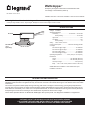
SPECIFICATIONS
Voltage 12-30VDC
Adjustments/Settings
Time Delay ................................ 30 seconds — 30 minutes
Factory Setting .......................................... 12 minutes
High Level .................................................................... 10V
Low Mode .................................................................... 1-5V
Factory Setting ....................................................... 1V
Wiring +24V, control, common
Current Consumption ..................... maximum 6.5mA @ 24VDC
Coverage
FS-L2W Lens @ 8’ height ............................... 48’ diameter
FS-L3W Lens @ 20’ height ............................. 40’ diameter
FS-L6 Lens @ 8’ height .................................. 20’ diameter
FS-L7W Lens @ 40’ height ........................... 100’ diameter
Operating Temperature ...............-40°F (-40°C) to 131°F (55°C)
Dimensions
Throat .......................................... 1.14” diameter (28.8mm)
Collar ........................................... 1.28” diameter (32.6mm)
Lens Pipe Length ......................................... 0.38” (9.6mm)
Body .... 1.38” x 2.35” x 0.88” (35mm x 59.5mm x 22.7mm)
OPEN DEVICE for installation in the Listed Enclosure per
Installation Instructions.
DESCRIPTION AND OPERATION
The FS-305-D occupancy sensor dims lighting from high to low based on occupancy levels. This slim, low-profile sensor is designed for
installation inside the bottom of a light fixture body. The PIR lens connects to the FS-305-D through a 11/8” diameter hole in the bottom
of the fixture.
The sensors use passive infrared (PIR) sensing technology that reacts to changes in infrared energy (moving body heat) within the
coverage area. Once the space is vacant and the time delay elapses (adjustable from 30 seconds to 30 minutes), lights will go to low
mode. Sensors must directly “see” motion of an occupant to detect them, so careful consideration must be given to sensor placement.
Avoid placing the sensor where shelving or other obstructions may block the sensor’s line of sight.
The FS-305-D operates between 12-30VDC with Wattstopper class 2 power packs. It is designed for installation in a light fixture.
FS-LxW Lens
(sold
separately)
FS-305-D
OUTDOOR USE AT THE SENSOR COLLAR PART ONLY WHEN (SENSOR
COLLAR PART EXPOSED AND) INSTALLED AT THE SPECIFIC LOCATION PER
INSTALLATION INSTRUCTIONS WITH A LISTED OUTDOOR ENCLOSURE.

2
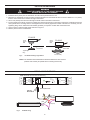
INSTALLATION AND WIRING
1. Install the FS-PP power pack as described in the instructions provided with the unit.
2. Determine an appropriate mounting location inside the light fixture for the FS-305-D. Allow a minimum distance of 1.3” (33mm)
from the center of the sensor collar to the edge of the fixture.
3. Use a 11/8” (29mm) bit to drill a hole through the sheet metal in the bottom of the fixture.
4. From the inside of the fixture, insert the FS-305-D lens pipe through the hole in the bottom of the fixture. Install the sensor face
down, parallel to the mounting surface. Hand tighten the Lens securely against the outside of the fixture. If necessary, use the
Tightening Ring, with or without the metal washer (provided), as a spacer on either side of the fixture wall.
5. Connect control, load and supply wires as shown in Figure 2.
6. Restore power from the circuit breaker.
FS-305-D
Inside
Fixture
Wall
Outside
Fixture Wall
FS-305-D
Lens Assembly
Inside
Fixture
Wall
Outside
Fixture Wall
Tightening
Ring
NOTE: The Outside Fixture Wall thickness should be between 0.032” and 0.10”
(0.82mm and 2.54mm) for optimal sensor mounting and security.
Fig 1: FS‑305‑D mounting in light xture
WIRING A SINGLE SENSOR
0-10V BALLAST
BLK
RED
YEL
RJ45 Plug
Model # FS-C3
Green Operation LED
NOTE: See FS-PP v2 Instructions for load wiring
GREY
VIO
FS-PP
GROUND
NEUTRAL
HOT
COM
N/O
N/C
03500r1
ISOLATED RELAY
OUTPUTS
TO LOAD
RJ45
TO SENSOR
88T9
Appliance
Control
LISTED
C US
Fixture Sensor Power Pack
120-277VAC, 60Hz
@120VAC 5A (N/0)
3A (N/C)
@277VAC 4.3A (N/0)
2.5A (N/C)
Strip Gauge
12-18AWG
CU wire only
120-277VAC Input
Control (VIO)
+24V (RED)
Com (BLK)
www.legrand.us
800.879.8585
Fig 2: FS-305-D wiring
WARNING
TURN THE POWER OFF AT THE CIRCUIT BREAKER
BEFORE INSTALLING THE SENSOR.

3
LOW MODE FEATURE
The Low Mode feature will dim the lights to a selected level, when the space becomes unoccupied. This selectable mode ranges from
1V to 5V.
The Low Mode and Time Delay adjustment trimpots are located under the lens assembly.
The trimpots are accessed easily after the sensor is mounted in the fixture. Gently unscrew
the lens assembly. Do not remove the thumbscrew collar; it holds the sensor in place on the
fixture. Identify each trimpot.
Test Occupancy Sensor
1. Set Low mode to minimum (fully counter-clockwise, Factory setting) and Time Delay
to minimum (fully counterclockwise). Put the lens assembly back onto the sensor.
2. Move out of the sensor’s view. Lights will go into Low mode fter 30 seconds.
3. Move into the controlled area. The red LED in the sensor lens should illuminate and
the lights will go into High mode.
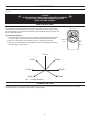
12 min.
18 min.6 min.
28 min.1.5 min.
30 min.30 sec.
Fig 3: Time Delay Parameters
CAUTION
DO NOT OVERTURN TRIMPOT WHEN ADJUSTING THE SENSOR.
DO NOT TOUCH THE SQUARE INFRARED DETECTOR
UNDER THE LENS ASSEMBLY.
COVERAGE PATTERN
Density and range of the coverage pattern is determined by the type of lens and mounting height. See the FS-LxW Lens Module
Coverage Guide for a description of the available coverage patterns.
SENSOR ADJUSTMENT
Low Mode
(1-5V)
Time
Delay
12
minutes
Factory Settings

800.879.8585
www.legrand.us/Wattstopper
No. 24040 – 07/18 rev. 2
© Copyright 2018 Legrand All Rights Reserved.
© Copyright 2018 Tous droits réservés Legrand.
© Copyright 2018 Legrand Todos los derechos reservados.
Wattstopper warranties its products to be free
of defects in materials and workmanship for a
period of five (5) years. There are no obligations
or liabilities on the part of Wattstopper for
consequential damages arising out of, or in
connection with, the use or performance of this
product or other indirect damages with respect
to loss of property, revenue or profit, or cost of
removal, installation or reinstallation.
Wattstopper garantit que ses produits sont
exempts de défauts de matériaux et de fabrication
pour une période de cinq (5) ans. Wattstopper
ne peut être tenu responsable de tout dommage
consécutif causé par ou lié à l’utilisation ou
à la performance de ce produit ou tout autre
dommage indirect lié à la perte de propriété, de
revenus, ou de profits, ou aux coûts d’enlèvement,
d’installation ou de réinstallation.
Wattstopper garantiza que sus productos
están libres de defectos en materiales y mano
de obra por un período de cinco (5) años. No
existen obligaciones ni responsabilidades por
parte de Wattstopper por daños consecuentes
que se deriven o estén relacionados con el
uso o el rendimiento de este producto u otros
daños indirectos con respecto a la pérdida
de propiedad, renta o ganancias, o al costo
de extracción, instalación o reinstalación.
WARRANTY INFORMATION INFORMATIONS RELATIVES À LA GARANTIE INFORMACIÓN DE LA GARANTÍA
TROUBLESHOOTING
Lights will not turn ON:
• LED does not flash - Check all wire connections.
• If lights still do not turn ON, call 800.879.8585.
Lights will not go LOW:
The time delay can be set from a minimum of 30 seconds (fully counter-clockwise) to a maximum of 30 minutes (fully clockwise). Ensure
that the time delay is set to the desired delay and that there is no movement within the sensor’s view for that time period.
• To quickly test the unit for proper operation, turn the time delay to minimum and move out of the sensor’s view. Lights should go LOW after 30
seconds.
• If lights still do not go LOW, call 800.879.8585 for technicalsupport.
Operation during Power-Up
During the sensor warm-up period, which can last up to a minute after initial power-up (or after a lengthy power outage), the load will
remain ON until the selected time delay expires.
ORDERING INFORMATION
Catalog # Description
FS-305-D Fixture mount, High/Low, low voltage occupancy sensor
FS-PP v2 Fixture mount power pack
BZ-50 Power Pack with flying leads for connecting low voltage wires
BZ-150 Power Pack with flying leads for connecting low voltage wires, hold-on/hold-off inputs, plus manual or auto mode option
FS-C2 One 6” (152mm) cable with 3 flying leads at one end and a shielded RJ45 male connector at the other (use with FS-PP)
FS-L2W 360° lens, maximum coverage 48’ diameter at 8’ height
FS-L3W 360° lens, maximum coverage 40’ diameter at 20’ height
FS-L6 360° lens, maximum coverage 20’ diameter at 8’ height
FS-L7W 360° lens, maximum coverage 100’ diameter at 40’ height
Sensor and Lenses are White. The FS-L7W is also available in gray (FS-L7-G).
6" (152mm)
-
 1
1
-
 2
2
-
 3
3
-
 4
4


Legrand FS-305-D High/Low Occupancy and Light Level Sensor Guide d'installation
- Catégorie
- Détecteurs de mouvement
- Taper
- Guide d'installation
dans d''autres langues
Documents connexes
-
Legrand FS-305 Low Voltage Occupancy and Light Level Sensor Guide d'installation
-
wattstopper A277C-P Guide d'installation
-
-
wattstopper FS-355 Line Voltage Occupancy and Light Level Sensor Guide d'installation
-
-
-
-
-
-