
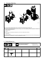
OWNER’S MANUAL
OM-264499F 2018−12
For Manual Slide (301137)
1. Safety Symbol Definitions
DANGER! − Indicates a hazardous situation which, if not
avoided, will result in death or serious injury. The possible
hazards are shown in the adjoining symbols or explained
in the text.
DANGER ! - Indique une situation dangereuse qui, si elle
n’est pas évitée, entraînera la mort ou des blessures
graves. Les éventuels risques sont représentés par les
symboles joints ou expliqués dans le texte.
Fsafe1 2013-10
Beware of electric shock from wiring. Disconnect input
power before installing this kit. Reinstall all panels and
covers.
Attention au risque d’électrocution due au contact avec
l’électrode de soudage ou les fils. Le fait de toucher
l’électrode tout en étant en contact avec la pièce ou la
terre peut provoquer une électrocution. Toujours porter
des gants secs. Tous les panneaux et couvercles doivent
rester fermés.
Fsafe6 2013-10
Indicates a hazardous situation which, if not avoided,
could result in death or serious injury. The possible ha-
zards are shown in the adjoining symbols or explained in
the text.
Indique une situation dangereuse qui, si elle n’est pas
évitée, entraînera la mort ou des blessures graves. Les
éventuels risques sont représentés par les symboles
joints ou expliqués dans le texte.
Fsafe2 2013-10
Falling equipment can injure, and damage equipment.
Never put any body part under unit while lifting. Lifting
forks must extend out opposite side of base. Lift and sup-
port unit only with proper equipment and correct proced-
ures. Follow the guidelines in the Applications Manual for
the Revised NIOSH Lifting Equation (Publication No.
94−110) when manually lifting heavy parts or equipment.
La chute de l’équipement peut provoquer des blessures
ou des dommages matériels. Ne jamais mettre une partie
du corps sous l’appareil pendant le levage. Les fourches
de levage doivent ressortir du côté opposé de la base. Ne
soulever l’appareil qu’avec un équipement en bon état
selon les procédures correctes. Suivre les consignes du
Manuel des applications pour l’équation de levage NIOSH
révisée (publication Nº 94–110) lors du levage manuel de
pièces ou équipements lourds.
Fsafe19 2013-10
NOTICE
NOTE
Indicates statements not related to personal injury.
Signale des consignes non associées aux dommages
corporels.
Indicates special instructions.
Fournit des instructions spéciales.
Fsafe3 2013-10
Wear safety glasses with side shields.
Porter des lunettes de sécurité avec écrans latéraux.
Fsafe8 2013-10
CALIFORNIA PROPOSITION 65 WARNINGS
WARNING: Cancer and Reproductive Harm − www.P65W
arnings.ca.gov
PROPOSITION CALIFORIENNE 65 AVERTISSEMENTS
AVERTISSEMENT : cancer et troubles de la reproduction − www.P65W
arnings.ca.gov
.
Fsafe26 2018-01
2. Description
The manual slide design provides horizontal or vertical movement of welding equipment. Two manual slides, connected as manual cross slides provide
both horizontal and vertical (X−Y) movement of welding equipment.
3. Specifications
Product Type Total Slide Movement Overall Dimensions Weight
Manual Slide 200 mm (7.87 in.) 480 mm x 150 mm x 80 mm
(18.90 in. x 5.91 in. x 3.15 in.)
8.48 kg
(18.7 lb)
4. Tools Needed
2.5 mm, 8 mm
9/16 in.

OM-264499 Page 2
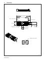
5. Dimensions
Diameter: 100 mm (3.94 in.)
270718-A
574 mm (22.60 in.)
480 mm (18.90 in.)
94 mm (3.70 in.)
110 mm
(4.33 in.)
64 mm (2.50 in.)
64 mm (2.50 in.)
51 mm (2.00 in.)
4 x 3/8 UNC-2B, 4 Places
150 mm (5.91 in.)
M10 x 1.5-6H, 4 Places

OM−264499 Page 3
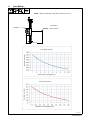
6. Load Rating
Slide Base
Load Weight
(Center of Mass)
DISTANCE
NOTICE − Maximum Load Rating: 100 kg (220 lb) at 400 mm (15-3/4 in.).
Maximum Load (Lbs)
Distance From Carriage Base (in.)
Maximum Load (kg)
Distance From Carriage Base (mm)
Cross Slide Load Chart
Cross Slide Load Chart
270719-A

OM-264499 Page 4
! Turn off wire feeder and welding
power source, and disconnect in-
put power before working on unit.
! Disconnect and lockout/tagout in-
put power before working on unit.
Follow established procedures re-
garding the installation and re-
moval of lockout/tagout devices.
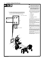
The manual slide may be mounted verti-
cally or horizontally, with the hand wheel
facing up or down, left or right (as needed).
1 Weld Fixture Mounting Plate Hole
Layout
2 Threaded Hole
3 Through Hole
4 Hand Wheel
5 Protective Guide (Bellows)
6 Carriage Plate
To gain access to mounting holes in slide
base, use a 2.5 mm Allen wrench to re-
move the four (two in each bellows)
screws that secure the bellows to the car-
riage plate. Retain screws.
Turn hand wheel to gain access to two of
the four mounting through holes located on
the base of the slide.
Align the two visible through holes in the
slide base with two of the desired threaded
holes in the mounting plate, and secure
with supplied M10 x 25 socket head
screws . Torque screws to 40 3 N
.
m (30
2 ft lb).
Turn hand wheel to move slide and allow
access to the remaining two through holes
in the slide base. Align holes as above, and
secure with remaining supplied M10 x 25
socket head screws. Torque screws to 40
3 N
.
m (30 2 ft lb).
Reattach bellows to carriage plate with
screws removed earlier and tighten with a
2.5 mm Allen wrench.
7. Installation (Manual Slide Shown)
2
3
4
2
3
5
6
M10 x 1.5-6H, 4 Places
110 mm (4.331 in.)
50 mm (1.966 in.)
. The slide is provided with M10 x 25 socket head hardware for
attaching the slide to the weld fixture mounting plate. If desired,
3/8 − 16 x 1.00 in. socket head hardware may be used. In this
case, the threaded hole should be adjusted accordingly.
271730-C
1

OM−264499 Page 5
! Turn off wire feeder and welding power source, and disconnect input power before working on unit.
! Disconnect and lockout/tagout input power before working on unit. Follow established procedures regarding the installation and
removal of lockout/tagout devices.
1 Mounting Hardware
2 Insulator
Remove the screws securing the large mounting plate (1) to the wire drive. Retain bolts and insulator.
3 Carriage Plate
4 Wire Drive Assembly
Place insulator, removed earlier, between drive assembly mounting plate and carriage plate, align holes and secure drive assembly with 3/8-16
bolts removed earlier. Torque bolts to 31 3 N
.
m (23 2 ft lb) with a 9/16 in. wrench.
8. Mounting A Wire Drive
1
2
4
3
271731-D
9. Routine Maintenance
. Maintain more often
during severe conditions.
! Disconnect and lockout/tagout
power before maintaining.
n = Check Reference
Monthly
Check condition of slide,
bearing, and female screw.
Replace if needed.
n
Every
3
Months
Section 10.
n Lubricate Parts

OM-264499 Page 6
! Turn off wire feeder and weld-
ing power source, and dis-
connect input power before
working on unit.
1 Side Plate
Using a 2.5 mm Allen wrench, re-
move side plates to gain access to
grease fittings. Apply grease.
Reinstall side plates when finished.
10. Greasing Slider Bearings
Ref. 270718-A
1
Notes

OM−264499 Page 7
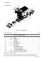
11. Parts List
.
Hardware is common and
not available unless listed.
16
5
3
19
15
8
14
2
18
6
9
3
19
5
19
15
14
2
1
19
4
19
17
10
17
13 7 19
4
19
10
17
19
16
12
11
12
271352-A
Figure 11-1. Complete Assembly
Description
Part
No.
Dia.
Mkgs.
Item
No.
Figure 11-1. Complete Assembly
Quantity
1 273170 Block, Sliding 2... .......... .. .......................................................
2 * Guide 2... ................ .. ..............................................................
3 273176 Bearing 2... .......... .. ............................................................
4 273177 Guide, Protective 2... .......... .. ....................................................
5 * Plate, End 2... ................ .. ..........................................................
6 * Plate, Base 1... ................ .. .........................................................
7 * Plate Carriage 1... ................ .. ......................................................
8 273175 Female Screw, Scroll 1... .......... .. ................................................
9 * Screw, Trapezoidal 1... ................ .. ..................................................
10 * Plate, Protective 2... ................ .. ....................................................
11 273174 Hand, Wheel 1... .......... .. .......................................................
12 * Pin, Dowel M4 x 8 2... ................ .. ...................................................
13 * Screw, Socket Head M5 x 16 8... ................ .. .........................................
14 * Screw, Socket Head M6 x 20 16... ................ .. ........................................
15 * Screw, Socket Head M6 x 25 2... ................ .. .........................................
16 * Screw, Socket Head M8 x 25 6... ................ .. .........................................
17 * Screw, Socket Head Countersunk M3 x 8 4... ................ .. ..............................
18 196418 Screw, M10−1.5 x 25 Soc Hd Cap Din 912 4... .......... .. .............................
19 273178 Screw, Socket Head Countersunk M4 x 8 8... .......... .. ..............................
* Consult factory for replacement part.
+When ordering a component originally displaying a precautionary label, the label should also be ordered.
BE SURE TO PROVIDE MODEL AND STYLE NUMBER WHEN ORDERING REPLACEMENT PARTS.
-
 1
1
-
 2
2
-
 3
3
-
 4
4
-
 5
5
-
 6
6
-
 7
7


Miller MF000000G Le manuel du propriétaire
- Taper
- Le manuel du propriétaire
- Ce manuel convient également à
dans d''autres langues
- English: Miller MF000000G Owner's manual
Documents connexes
-
Miller MF000000G Le manuel du propriétaire
-
-
-
Miller BIG BLUE 500 X (PERKINS) Le manuel du propriétaire
-
-
-
-
-
-
Miller Big Blue 400D Le manuel du propriétaire