ASROCK PV530 Le manuel du propriétaire
- Catégorie
- Cartes mères
- Taper
- Le manuel du propriétaire

11
11
1
ASRock PV530 Motherboard
EnglishEnglish
EnglishEnglish
English
Copyright Notice:Copyright Notice:
Copyright Notice:Copyright Notice:
Copyright Notice:
No part of this installation guide may be reproduced, transcribed, transmitted, or trans-
lated in any language, in any form or by any means, except duplication of documen-
tation by the purchaser for backup purpose, without written consent of ASRock Inc.
Products and corporate names appearing in this guide may or may not be registered
trademarks or copyrights of their respective companies, and are used only for identifica-
tion or explanation and to the owners’ benefit, without intent to infringe.
Disclaimer:Disclaimer:
Disclaimer:Disclaimer:
Disclaimer:
Specifications and information contained in this guide are furnished for informational
use only and subject to change without notice, and should not be constructed as a
commitment by ASRock. ASRock assumes no responsibility for any errors or omissions
that may appear in this guide.
With respect to the contents of this guide, ASRock does not provide warranty of any kind,
either expressed or implied, including but not limited to the implied warranties or
conditions of merchantability or fitness for a particular purpose. In no event shall
ASRock, its directors, officers, employees, or agents be liable for any indirect, special,
incidental, or consequential damages (including damages for loss of profits, loss of
business, loss of data, interruption of business and the like), even if ASRock has been
advised of the possibility of such damages arising from any defect or error in the guide
or product.
This device complies with Part 15 of the FCC Rules. Operation is subject to the
following two conditions:
(1) this device may not cause harmful interference, and
(2) this device must accept any interference received, including interference that
may cause undesired operation.
Published May 2010
Copyright©2010 ASRock INC. All rights reserved.
CALIFORNIA, USA ONLY
The Lithium battery adopted on this motherboard contains Perchlorate, a toxic
substance controlled in Perchlorate Best Management Practices (BMP) regulations
passed by the California Legislature. When you discard the Lithium battery in
California, USA, please follow the related regulations in advance.
“Perchlorate Material-special handling may apply, see
www.dtsc.ca.gov/hazardouswaste/perchlorate”
ASRock Website: http://www.asrock.com

22
22
2
ASRock PV530 Motherboard
EnglishEnglish
EnglishEnglish
English
Motherboard LMotherboard L
Motherboard LMotherboard L
Motherboard L
ayoutayout
ayoutayout
ayout
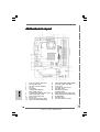
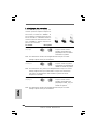
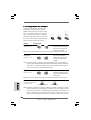
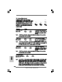
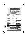
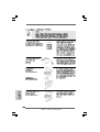
1 Power Fan Connector (PWR_FAN1) 13 Chassis Speaker Header (SPEAKER 1, White)
2 PS2_USB_PWR1 Jumper 14 Clear CMOS Jumper (CLRCMOS1)
3 ATX Power Connector (ATXPWR1) 15 PCI Slot (PCI1)
4 CPU Fan 16 PCI Express 2.0 x16 Slot (PCIE1)
5 CPU Heatsink 17 USB_PWR3 Jumper
6 2 x 240-pin DDR2 DIMM Slots 18 Front Panel Audio Header
(DDRII_1, DDRII_2; Yellow) (HD_AUDIO1, White)
7 1 x 240-pin DDR3 DIMM Slot (DDR3_1; Blue) 19 Primary SATAII Connector (SATAII_1; Blue)
8 USB 2.0 Header (USB6_7, Blue) 20 Secondary SATAII Connector (SATAII_2; Blue)
9 USB 2.0 Header (USB4_5, Blue) 21 VIA VX900 Chipset
10 BIOS SPI Chip 22 USB_PWR2 Jumper
11 Chassis Fan Connector (CHA_FAN1) 23 CPU Fan Connector (CPU_FAN1)
12 System Panel Header (PANEL1, White)

33
33
3
ASRock PV530 Motherboard
EnglishEnglish
EnglishEnglish
English
I/O PI/O P
I/O PI/O P
I/O P
anelanel
anelanel
anel
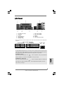
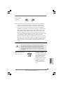
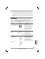
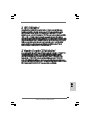
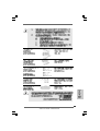
1 PS/2 Mouse Port (Green) 7 USB 2.0 Ports (USB01)
2 Parallel Port 8 USB 2.0 Ports (USB23)
3 RJ-45 Port 9 VGA Port
4 Line In (Light Blue) 10 COM Port
5 Line Out (Lime) 11 PS/2 Keyboard Port (Purple)
6 Microphone (Pink)
LAN Port
ACT/LINK
LED
SPEED
LED
* There are two LED next to the LAN port. Please refer to the table below for the LAN port LED
indications.
LAN Port LED Indications
Activity/Link LED SPEED LED
Status Description Status Description
Off No Activity Off 10Mbps connection
Blinking Data Activity Green 100Mbps connection
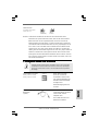
To enable Multi-Streaming function, you need to connect a front panel audio cable to the front
panel audio header. After restarting your computer, you will find “VIA HD Audio Deck” tool on
your system. Please follow below instructions according to the OS you install.
For Windows
®
XP OS:
Please click “VIA HD Audio Deck” icon , and click “Speaker”. Then you are allowed to
select “2 Channel” or “4 Channel”. Click “Power” to save your change.
For Windows
®
7 / Vista
TM
OS:
Please click “VIA HD Audio Deck” icon , and click “Advanced Options” on the left side
on the bottom. In “Advanced Options” screen, select “Independent Headphone”, and click
“OK” to save your change.

44
44
4
ASRock PV530 Motherboard
EnglishEnglish
EnglishEnglish
English
1. Introduction1. Introduction
1. Introduction1. Introduction
1. Introduction
Thank you for purchasing ASRock PV530 motherboard, a reliable motherboard pro-
duced under ASRock’s consistently stringent quality control. It delivers excellent
performance with robust design conforming to ASRock’s commitment to quality and
endurance.
This Quick Installation Guide contains introduction of the motherboard and step-by-
step installation guide. More detailed information of the motherboard can be found in
the user manual presented in the Support CD.
Because the motherboard specifications and the BIOS software might
be updated, the content of this manual will be subject to change without
notice. In case any modifications of this manual occur, the updated
version will be available on ASRock website without further notice. You
may find the latest VGA cards and CPU support lists on ASRock website
as well. ASRock website http://www.asrock.com
If you require technical support related to this motherboard, please visit
our website for specific information about the model you are using.
www.asrock.com/support/index.asp
1.1 Package Contents1.1 Package Contents
1.1 Package Contents1.1 Package Contents
1.1 Package Contents
ASRock PV530 Motherboard
(Micro ATX Form Factor: 8.5-in x 6.7-in, 21.6 cm x 17.0 cm)
ASRock PV530 Quick Installation Guide
ASRock PV530 Support CD
Two Serial ATA (SATA) Data Cables (Optional)
One I/O Panel Shield

55
55
5
ASRock PV530 Motherboard
EnglishEnglish
EnglishEnglish
English
1.21.2
1.21.2
1.2
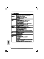
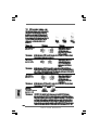
SpecificationsSpecifications
SpecificationsSpecifications
Specifications
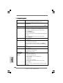
Platform - Micro ATX Form Factor: 8.5-in x 6.7-in, 21.6 cm x 17.0 cm
- Solid Capacitor for CPU power
CPU - VIA
®
PV530 Processor (1.8 GHz)
- Supports FSB800 MHz
- Supports Untied Overclocking Technology (see CAUTION 1)
Chipset - VIA
®
VX900
Memory - 1 x DDR3 DIMM slot
- Supports DDR3 800 non-ECC, un-buffered memory
- Max. capacity of system memory: 4GB (see CAUTION 2)
- 2 x DDR2 DIMM slots
- Supports DDR2 800/667/533 non-ECC, un-buffered memory
- Max. capacity of system memory: 4GB (see CAUTION 2)
Expansion Slot - 1 x PCI Express 2.0 x16 slot (blue @ x8 mode)
- 1 x PCI slot
Graphics - VIA
®
Chrome9 HD DX9 Graphics
- Pixel Shader 2.0, DirectX 9.0
- Max. shared memory 512MB (see CAUTION 3)
- Supports D-Sub with max. resolution up to 2048x1536
@ 75Hz
Audio - 5.1 CH HD Audio (VIA
®
VT1705 Audio Codec)
LAN - Atheros
®
PCIEx1 LAN AR8132L
- Speed: 10/100 Ethernet
- Supports Wake-On-LAN
Rear Panel I/O I/O Panel
- 1 x PS/2 Mouse Port
- 1 x PS/2 Keyboard Port
- 1 x Parallel Port (ECP/EPP Support)
- 1 x Serial Port: COM1
- 1 x VGA Port
- 4 x Ready-to-Use USB 2.0 Ports
- 1 x RJ-45 LAN Port with LED (ACT/LINK LED and SPEED LED)
- HD Audio Jack: Line in / Front Speaker / Microphone
Connector - 2 x SATAII 3.0 Gb/s connectors (see CAUTION 4)
- CPU/Chassis/Power FAN connector
- 24 pin ATX power connector
- Front panel audio connector
- 2 x USB 2.0 headers (support 4 USB 2.0 ports)

66
66
6
ASRock PV530 Motherboard
EnglishEnglish
EnglishEnglish
English
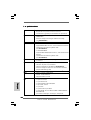
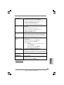
BIOS Feature - 4Mb AMI BIOS
- AMI Legal BIOS
- Supports “Plug and Play”
- ACPI 1.1 Compliance Wake Up Events
- Supports jumperfree
- AMBIOS 2.3.1 Support
Support CD - Drivers, Utilities, AntiVirus Software (Trial Version), ASRock
Software Suite (CyberLink DVD Suite - OEM and Trial;
Creative Sound Blaster X-Fi MB - Trial)
Unique Feature - ASRock OC Tuner (see CAUTION 5)
- Instant Boot
- ASRock Instant Flash (see CAUTION 6)
- ASRock OC DNA (see CAUTION 7)
- Hybrid Booster:
- CPU Frequency Stepless Control (see CAUTION 8)
- ASRock U-COP (see CAUTION 9)
- Boot Failure Guard (B.F.G.)
Hardware - CPU Temperature Sensing
Monitor - Chassis Temperature Sensing
- CPU/Chassis/Power Fan Tachometer
- Voltage Monitoring: +12V, +5V, +3.3V, Vcore
OS - Microsoft
®
Windows
®
7 / Vista
TM
/ XP compliant
Certifications - FCC, CE, WHQL
- ErP/EuP Ready (ErP/EuP ready power supply is required)
(see CAUTION 10)
* For detailed product information, please visit our website: http://www.asrock.com
WARNING
Please realize that there is a certain risk involved with overclocking, including adjusting
the setting in the BIOS, applying Untied Overclocking Technology, or using the third-
party overclocking tools. Overclocking may affect your system stability, or even
cause damage to the components and devices of your system. It should be done at
your own risk and expense. We are not responsible for possible damage caused by
overclocking.

77
77
7
ASRock PV530 Motherboard
EnglishEnglish
EnglishEnglish
English
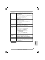
CAUTION!
1. This motherboard supports Untied Overclocking Technology. Please read “Un-
tied Overclocking Technology” on page 15 for details.
2. Due to the chipset limitation, the actual memory size may be less than
4GB for the reservation for system usage under Windows
®
OS.
3. The maximum shared memory size is defined by the chipset vendor and
is subject to change. Please check VIA
®
website for the latest information.
4. Before installing SATAII hard disk to SATAII connector, please read the “SATAII
Hard Disk Setup Guide” on page 18 of “User Manual” in the support CD to
adjust your SATAII hard disk drive to SATAII mode. You can also connect SATA
hard disk to SATAII connector directly.
5. It is a user-friendly ASRock overclocking tool which allows you to surveil
your system by hardware monitor function and overclock your hardware
devices to get the best system performance under Windows
®
environment.
Please visit our website for the operation procedures of ASRock OC
Tuner. ASRock website: http://www.asrock.com
6. ASRock Instant Flash is a BIOS flash utility embedded in Flash ROM.
This convenient BIOS update tool allows you to update system BIOS
without entering operating systems first like MS-DOS or Windows
®
. With
this utility, you can press <F6> key during the POST or press <F2> key to
BIOS setup menu to access ASRock Instant Flash. Just launch this tool
and save the new BIOS file to your USB flash drive, floppy disk or hard
drive, then you can update your BIOS only in a few clicks without prepar-
ing an additional floppy diskette or other complicated flash utility. Please
be noted that the USB flash drive or hard drive must use FAT32/16/12 file
system.
7. The software name itself – OC DNA literally tells you what it is capable of.
OC DNA, an exclusive utility developed by ASRock, provides a conve-
nient way for the user to record the OC settings and share with others. It
helps you to save your overclocking record under the operating system
and simplifies the complicated recording process of overclocking settings.
With OC DNA, you can save your OC settings as a profile and share with
your friends! Your friends then can load the OC profile to their own system
to get the same OC settings as yours! Please be noticed that the OC
profile can only be shared and worked on the same motherboard.
8. Although this motherboard offers stepless control, it is not recommended
to perform over-clocking. Frequencies other than the recommended CPU
bus frequencies may cause the instability of the system or damage the
CPU.
9. While CPU overheat is detected, the system will automatically shutdown.
Before you resume the system, please check if the CPU fan on the
motherboard functions properly and unplug the power cord, then plug it
back again. To improve heat dissipation, remember to spray thermal
grease between the CPU and the heatsink when you install the PC system.

88
88
8
ASRock PV530 Motherboard
EnglishEnglish
EnglishEnglish
English
10. EuP, stands for Energy Using Product, was a provision regulated by
European Union to define the power consumption for the completed system.
According to EuP, the total AC power of the completed system shall be
under 1.00W in off mode condition. To meet EuP standard, an EuP ready
motherboard and an EuP ready power supply are required. According to
Intel’s suggestion, the EuP ready power supply must meet the standard of
5v standby power efficiency is higher than 50% under 100 mA current
consumption. For EuP ready power supply selection, we recommend you
checking with the power supply manufacturer for more details.

99
99
9
ASRock PV530 Motherboard
EnglishEnglish
EnglishEnglish
English
2. Installation2. Installation
2. Installation2. Installation
2. Installation
PV530 is a Micro ATX form factor (8.5" x 6.7", 21.6 x 17.0 cm) motherboard. Before
you install the motherboard, study the configuration of your chassis to ensure that
the motherboard fits into it.
Make sure to unplug the power cord before installing or removing the
motherboard. Failure to do so may cause physical injuries to you and
damages to motherboard components.
2.1 Screw Holes2.1 Screw Holes
2.1 Screw Holes2.1 Screw Holes
2.1 Screw Holes
Place screws into the holes indicated by circles to secure the motherboard to the
chassis.
Do not over-tighten the screws! Doing so may damage the motherboard.
2.2 Pre-installation Precautions2.2 Pre-installation Precautions
2.2 Pre-installation Precautions2.2 Pre-installation Precautions
2.2 Pre-installation Precautions
Take note of the following precautions before you install motherboard components
or change any motherboard settings.
1. Unplug the power cord from the wall socket before touching any component.
2. To avoid damaging the motherboard components due to static electricity, NEVER
place your motherboard directly on the carpet or the like. Also remember to use
a grounded wrist strap or touch a safety grounded object before you handle
components.
3. Hold components by the edges and do not touch the ICs.
4. Whenever you uninstall any component, place it on a grounded antistatic pad or
in the bag that comes with the component.
Before you install or remove any component, ensure that the power is
switched off or the power cord is detached from the power supply.
Failure to do so may cause severe damage to the motherboard, peripherals,
and/or components.

1010
1010
10
ASRock PV530 Motherboard
EnglishEnglish
EnglishEnglish
English
2.3 Installation of Memory Modules (DIMM)2.3 Installation of Memory Modules (DIMM)
2.3 Installation of Memory Modules (DIMM)2.3 Installation of Memory Modules (DIMM)
2.3 Installation of Memory Modules (DIMM)
PV530 motherboard provides one 240-pin DDR3 (Double Data Rate 3) DIMM slot and
two 240-pin DDR2 (Double Data Rate 2) DIMM slots.
1. It is not allowed to install a DDR memory module into DDR2 slot or
a DDR/DDR2 memory module into DDR3 slot; otherwise, this
motherboard and DIMM may be damaged.
2. Please do not use the DDR2 slots and DDR3 slot at the same time.
You can choose to install either DDR2 or DDR3 memory module.
Installing a DIMMInstalling a DIMM
Installing a DIMMInstalling a DIMM
Installing a DIMM
Please make sure to disconnect power supply before adding or
removing DIMMs or the system components.
Step 1. Unlock a DIMM slot by pressing the retaining clips outward.
Step 2. Align a DIMM on the slot such that the notch on the DIMM matches the break
on the slot.
The DIMM only fits in one correct orientation. It will cause permanent
damage to the motherboard and the DIMM if you force the DIMM into the
slot at incorrect orientation.
Step 3. Firmly insert the DIMM into the slot until the retaining clips at both ends fully
snap back in place and the DIMM is properly seated.

1111
1111
11
ASRock PV530 Motherboard
EnglishEnglish
EnglishEnglish
English
2.4 Expansion Slots (PCI and PCI Express Slots)2.4 Expansion Slots (PCI and PCI Express Slots)
2.4 Expansion Slots (PCI and PCI Express Slots)2.4 Expansion Slots (PCI and PCI Express Slots)
2.4 Expansion Slots (PCI and PCI Express Slots)
There are 1 PCI slot and 1 PCI Express slot on this motherboard.
PCI Slot: PCI slot is used to install expansion card that has the 32-bit PCI
interface.
PCIE Slot: PCIE1 (PCIE x16 slot; Blue) is used for PCI Express x16 lane width
graphics card.
Installing an expansion cardInstalling an expansion card
Installing an expansion cardInstalling an expansion card
Installing an expansion card
Step 1. Before installing the expansion card, please make sure that the power
supply is switched off or the power cord is unplugged. Please read the
documentation of the expansion card and make necessary hardware
settings for the card before you start the installation.
Step 2. Remove the system unit cover (if your motherboard is already installed in
a chassis).
Step 3. Remove the bracket facing the slot that you intend to use. Keep the
screws for later use.
Step 4. Align the card connector with the slot and press firmly until the card is
completely seated on the slot.
Step 5. Fasten the card to the chassis with screws.
Step 6. Replace the system cover.

1212
1212
12
ASRock PV530 Motherboard
EnglishEnglish
EnglishEnglish
English
2.52.5
2.52.5
2.5
Jumpers SetupJumpers Setup
Jumpers SetupJumpers Setup
Jumpers Setup
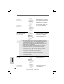
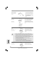
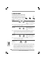
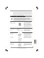
The illustration shows how jumpers are
setup. When the jumper cap is placed on
pins, the jumper is “Short”. If no jumper cap
is placed on pins, the jumper is “Open”. The
illustration shows a 3-pin jumper whose pin1
and pin2 are “Short” when jumper cap is
placed on these 2 pins.
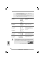
Jumper Setting
PS2_USB_PWR1 Short pin2, pin3 to enable
(see p.2, No. 2) +5VSB (standby) for PS/2 or
USB23 wake up events.
Note: To select +5VSB, it requires 2 Amp and higher standby current provided by
power supply.
USB_PWR2 Short pin2, pin3 to enable
(see p.2, No. 22) +5V_DUAL for USB01 wake
up events.
Note: To select +5V_DUAL, it requires 2 Amp and higher standby current provided
by power supply. When you select +5V_DUAL, USB devices can wake up
the system under S3 (Suspend to RAM) state.
USB_PWR3 Short pin2, pin3 to enable
(see p.2, No. 17) +5VSB (standby) for
USB4_5/6_7 wake up
events.
Note: To select +5VSB, it requires 2 Amp and higher standby current provided by
power supply.
Clear CMOS Jumper
(CLRCMOS1)
(see p.2, No. 14)
Note: CLRCMOS1 allows you to clear the data in CMOS. The data in CMOS includes
system setup information such as system password, date, time, and system
setup parameters. To clear and reset the system parameters to default setup,
please turn off the computer and unplug the power cord from the power
supply. After waiting for 15 seconds, use a jumper cap to short pin2 and pin3
on CLRCMOS1 for 5 seconds. However, please do not clear the CMOS right
after you update the BIOS. If you need to clear the CMOS when you just finish
updating the BIOS, you must boot up the system first, and then shut it down
before you do the clear-CMOS action.
Clear CMOSDefault
Short Open

1313
1313
13
ASRock PV530 Motherboard
EnglishEnglish
EnglishEnglish
English
Front Panel Audio Header This is an interface for front
(9-pin HD_AUDIO1) panel audio cable that allows
(see p.2 No. 18) convenient connection and
control of audio devices.
USB 2.0 Headers Besides four default USB 2.0
(9-pin USB6_7) ports on the I/O panel, there are
(see p.2 No. 8) two USB 2.0 headers on this
motherboard. Each USB 2.0
header cansupport two USB
2.0 ports.
(9-pin USB4_5)
(see p.2 No. 9)
2.6 Onboard Headers and Connectors2.6 Onboard Headers and Connectors
2.6 Onboard Headers and Connectors2.6 Onboard Headers and Connectors
2.6 Onboard Headers and Connectors
Onboard headers and connectors are NOT jumpers. Do NOT place
jumper caps over these headers and connectors. Placing jumper caps
over the headers and connectors will cause permanent damage of the
motherboard!
Serial ATAII Connectors These Serial ATAII (SATAII)
(SATAII_1: see p.2, No. 20) connectors support SATAII
(SATAII_2: see p.2, No. 19) or SATA hard disk for internal
storage devices. The current
SATAII interface allows up to
3.0 Gb/s data transfer rate.
Serial ATA (SATA) Either end of the SATA data cable
Data Cable can be connected to the SATA /
(Optional) SATAII hard disk or the SATAII
connector on the motherboard.
1. High Definition Audio supports Jack Sensing, but the panel wire on
the chassis must support HDA to function correctly. Please follow the
instruction in our manual and chassis manual to install your system.
2. If you use AC’97 audio panel, please install it to the front panel audio
header as below:
SATAII_2
SATAII_1

1414
1414
14
ASRock PV530 Motherboard
EnglishEnglish
EnglishEnglish
English
System Panel Header This header accommodates
(9-pin PANEL1) several system front panel
(see p.2 No. 12) functions.
Chassis Speaker Header Please connect the chassis
(4-pin SPEAKER 1) speaker to this header.
(see p.2 No. 13)
Chassis and Power Fan Connectors Please connect the fan cables
(3-pin CHA_FAN1) to the fan connectors and
(see p.2 No. 11) match the black wire to the
ground pin.
(3-pin PWR_FAN1)
(see p.2 No. 1)
CPU Fan Connector Please connect a CPU fan cable
(3-pin CPU_FAN1) to this connector and match
(see p.2 No. 23) the black wire to the ground pin.
ATX Power Connector Please connect an ATX power
(24-pin ATXPWR1) supply to this connector.
(see p.2, No. 3)
A. Connect Mic_IN (MIC) to MIC2_L.
B. Connect Audio_R (RIN) to OUT2_R and Audio_L (LIN) to OUT2_L.
C. Connect Ground (GND) to Ground (GND).
D. MIC_RET and OUT_RET are for HD audio panel only. You don’t
need to connect them for AC’97 audio panel.
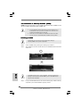
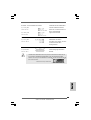
20-Pin ATX Power Supply Installation
Though this motherboard provides 24-pin ATX power connector, it can still work
if you adopt a traditional 20-pin ATX power supply. To use the 20-pin ATX power
supply, please plug your power supply along with Pin 1 and Pin 13.
24 13
12 1
24 13
12 1

1515
1515
15
ASRock PV530 Motherboard
EnglishEnglish
EnglishEnglish
English
2.82.8
2.82.8
2.8
Untied Overclocking TUntied Overclocking T
Untied Overclocking TUntied Overclocking T
Untied Overclocking T
echnologyechnology
echnologyechnology
echnology
This motherboard supports Untied Overclocking Technology, which means during
overclocking, FSB enjoys better margin due to fixed PCI bus. Before you enable
Untied Overclocking function, please enter “Overclock Mode” option of BIOS setup to
set the selection from [Auto] to [CPU, PCIE, Async.]. Therefore, CPU FSB is untied
during overclocking, but PCI buse is in the fixed mode so that FSB can operate under
a more stable overclocking environment.
Please refer to the warning on page 6 for the possible overclocking risk
before you apply Untied Overclocking Technology.
2.72.7
2.72.7
2.7
Driver Installation GuideDriver Installation Guide
Driver Installation GuideDriver Installation Guide
Driver Installation Guide
To install the drivers to your system, please insert the support CD to your optical
drive first. Then, the drivers compatible to your system can be auto-detected and
listed on the support CD driver page. Please follow the order from up to bottom
side to install those required drivers. Therefore, the drivers you install can work
properly.

1616
1616
16
ASRock PV530 Motherboard
3. BIOS Information3. BIOS Information
3. BIOS Information3. BIOS Information
3. BIOS Information
The Flash Memory on the motherboard stores BIOS Setup Utility. When you start up
the computer, please press <F2> during the Power-On-Self-Test (POST) to enter
BIOS Setup utility; otherwise, POST continues with its test routines. If you wish to
enter BIOS Setup after POST, please restart the system by pressing <Ctl> + <Alt> +
<Delete>, or pressing the reset button on the system chassis. The BIOS Setup pro-
gram is designed to be user-friendly. It is a menu-driven program, which allows you to
scroll through its various sub-menus and to select among the predetermined choices.
For the detailed information about BIOS Setup, please refer to the User Manual (PDF
file) contained in the Support CD.
4. Sof4. Sof
4. Sof4. Sof
4. Sof
tware Supportware Suppor
tware Supportware Suppor
tware Suppor
t CD informationt CD information
t CD informationt CD information
t CD information
This motherboard supports various Microsoft
®
Windows
®
operating systems: 7 /
Vista
TM
/ XP. The Support CD that came with the motherboard contains necessary
drivers and useful utilities that will enhance motherboard features. To begin using
the Support CD, insert the CD into your CD-ROM drive. It will display the Main Menu
automatically if “AUTORUN” is enabled in your computer. If the Main Menu does not
appear automatically, locate and double-click on the file “ASSETUP.EXE” from the BIN
folder in the Support CD to display the menus.
EnglishEnglish
EnglishEnglish
English

1717
1717
17
ASRock PV530 Motherboard
DeutschDeutsch
DeutschDeutsch
Deutsch
1. Einführung1. Einführung
1. Einführung1. Einführung
1. Einführung
Wir danken Ihnen für den Kauf des ASRock PV530 Motherboard, ein zuverlässiges
Produkt, welches unter den ständigen, strengen Qualitätskontrollen von ASRock
gefertigt wurde. Es bietet Ihnen exzellente Leistung und robustes Design, gemäß der
Verpflichtung von ASRock zu Qualität und Halbarkeit.
Diese Schnellinstallationsanleitung führt in das Motherboard und die schrittweise
Installation ein. Details über das Motherboard finden Sie in der
Bedienungsanleitung auf der Support-CD.
Da sich Motherboard-Spezifikationen und BIOS-Software verändern
können, kann der Inhalt dieses Handbuches ebenfalls jederzeit geändert
werden. Für den Fall, dass sich Änderungen an diesem Handbuch
ergeben, wird eine neue Version auf der ASRock-Website, ohne weitere
Ankündigung, verfügbar sein. Die neuesten Grafikkarten und unterstützten
CPUs sind auch auf der ASRock-Website aufgelistet.
ASRock-Website: http://www.asrock.com
Wenn Sie technische Unterstützung zu Ihrem Motherboard oder spezifische
Informationen zu Ihrem Modell benötigen, besuchen Sie bitte unsere
Webseite:
www.asrock.com/support/index.asp
1.1 Kartoninhalt
ASRock PV530 Motherboard
(Micro ATX-Formfaktor: 21.6 cm x 17.0 cm; 8.5 Zoll x 6.7 Zoll)
ASRock PV530 Schnellinstallationsanleitung
ASRock PV530_ Support-CD
Zwei Seriell-ATA- (SATA) Datenkabel (Option)
Ein I/O Shield

1818
1818
18
ASRock PV530 Motherboard
DeutschDeutsch
DeutschDeutsch
Deutsch
1.21.2
1.21.2
1.2
SpezifikationenSpezifikationen
SpezifikationenSpezifikationen
Spezifikationen
Plattform - Micro ATX-Formfaktor: 21.6 cm x 17.0 cm; 8.5 Zoll x 6.7 Zoll
- Festkondensator für CPU-Leistung
CPU - VIA
®
PV530-Prozessor (1.8 GHz)
- Unterstützt FSB800 MHz
- Unterstützt Untied-Übertaktungstechnologie
(siehe VORSICHT 1)
Chipsatz - VIA
®
VX900
Speicher - 1 x Steckplätze für DDR3
- Unterstützt DDR3 800 non-ECC, ungepufferter Speicher
- Max. Kapazität des Systemspeichers: 4GB
(siehe VORSICHT 2)
- 2 x Steckplätze für DDR2
- Unterstützt DDR2 800/667/533 non-ECC, ungepufferter
Speicher
- Max. Kapazität des Systemspeichers: 4GB
(siehe VORSICHT 2)
Erweiterungs- - 1 x PCI Express 2.0 x16-Steckplätze (blau für x8-Modus)
steckplätze - 1 x PCI -Steckplätze
Onboard-VGA - VIA
®
Chrome9 HD DX9-Grafikkarte
- Pixel Shader 2.0, DX9.0 VGA
- Maximal gemeinsam genutzter Speicher 512MB
(siehe VORSICHT 3)
- Unterstützt D-Sub mit einer maximalen Auflösung von
2048 x 1536 bei 75 Hz
Audio - 5.1 CH HD Audio (VIA
®
VT1705 Audio Codec)
LAN - Atheros
®
PCIEx1 LAN AR8132L
- Speed: 10/100 Ethernet
- Unterstützt Wake-On-LAN
E/A-Anschlüsse I/O Panel
an der - 1 x PS/2 Mouse Port
Rückseite - 1 x PS/2 Keyboard Port
- 1 x Parallel Port (ECP/EPP Support)
- 1 x Serieller port: COM 1
- 1 x VGA Port
- 4 x Ready-to-Use USB 2.0 Ports
- 1 x RJ-45 LAN Port mit LED (ACT/LINK LED und SPEED LED)
- Audioanschlüsse: Line In / Line Out / Mikrofon
Anschlüsse - 2 x SATAII-Anschlüsse, unterstützt bis 3.0 Gb/s
Datenübertragungsrate (siehe VORSICHT 4)
- CPU/Gehäuse/Stromlüfter-Anschluss

1919
1919
19
ASRock PV530 Motherboard
DeutschDeutsch
DeutschDeutsch
Deutsch
- 24-pin ATX-Netz-Header
- Anschluss für Audio auf der Gehäusevorderseite
- 2 x USB 2.0 Buchse (unterstützt 4 USB 2.0 Ports)
BIOS - 4Mb AMI BIOS
- AMI legal BIOS mit Unterstützung für “Plug and Play”
- ACPI 1.1-Weckfunktionen
- JumperFree-Modus
- SMBIOS 2.3.1
Support-CD - Treiber, Dienstprogramme, Antivirussoftware
(Probeversion), ASRock-Software-Suite (CyberLink
DVD Suite und Creative Sound Blaster X-Fi MB) (OEM- und
Testversion)
Einzigartige - ASRock OC Tuner (siehe VORSICHT 5)
Eigenschaft - Sofortstart
- ASRock Instant Flash (siehe VORSICHT 6)
- ASRock OC DNA (siehe VORSICHT 7)
- Hybrid Booster:
- Schrittloser CPU-Frequenz-Kontrolle
(siehe VORSICHT 8)
- ASRock U-COP (siehe VORSICHT 9)
- Boot Failure Guard (B.F.G. – Systemstartfehlerschutz)
Hardware Monitor - Überwachung der CPU-Temperatur
- Motherboardtemperaturerkennung
- Drehzahlmessung für CPU/Gehäuse/Stromlüfter
- Spannungsüberwachung: +12V, +5V, +3.3V, Vcore
Betriebssysteme - Unterstützt Microsoft
®
Windows
®
7 / Vista
TM
/ XP
Zertifizierungen - FCC, CE, WHQL
- Gemäß Ökodesign-Richtlinie (ErP/EuP) (Stromversorgung
gemäß Ökodesign-Richtlinie (ErP/EuP) erforderlich)
(siehe VORSICHT 10)
* Für die ausführliche Produktinformation, besuchen Sie bitte unsere Website:
http://www.asrock.com
WARNUNG
Beachten Sie bitte, dass Overclocking, einschließlich der Einstellung im BIOS, Anwenden
der Untied Overclocking-Technologie oder Verwenden von Overclocking-Werkzeugen von
Dritten, mit einem gewissen Risiko behaftet ist. Overclocking kann sich nachteilig auf die
Stabilität Ihres Systems auswirken oder sogar Komponenten und Geräte Ihres Systems
beschädigen. Es geschieht dann auf eigene Gefahr und auf Ihre Kosten. Wir übernehmen
keine Verantwortung für mögliche Schäden, die aufgrund von Overclocking verursacht
wurden.

2020
2020
20
ASRock PV530 Motherboard
DeutschDeutsch
DeutschDeutsch
Deutsch
VORSICHT!
1. Dieses Motherboard unterstützt die Untied-Übertaktungstechnologie.
Unter “Entkoppelte Übertaktungstechnologie” auf Seite 15 finden Sie
detaillierte Informationen.
2. Aufgrund von Chipset-Einschränkungen könnte unter Windows
®
OS die
für das System reservierte Speichergröße unterhalb von 4 GB liegen.
3. Die Maximalspeichergröße ist von den Chipshändler definiert und
umgetauscht. Bitte überprüfen Sie VIA
®
website für die neuliche Information.
4. Vor Installation der SATAII-Festplatte an den SATAII-Anschluss lesen Sie
bitte “Setup-Anleitung für SATAII-Festplatte” auf Seite 18 der
“Bedienungsanleitung” auf der Support-CD, um Ihre SATAII-Festplatte
dem SATAII-Modus anzugleichen. Sie können die SATA-Festplatte auch
direkt mit dem SATAII-Anschluss verbinden.
5. Es ist ein benutzerfreundlicher ASRock Übertaktenswerkzeug, das
erlaubt, dass Sie Ihr System durch den Hardware-Monitor Funktion zu
überblicken und Ihre Hardware-Geräte übertakten, um die beste
Systemleistung unter der Windows
®
Umgebung zu erreichen. Besuchen
Sie bitte unsere Website für die Operationsverfahren von ASRock OC
Tuner. ASRock-Website: http://www.asrock.com
6. ASRock Instant Flash ist ein im Flash-ROM eingebettetes BIOS-Flash-
Programm. Mithilfe dieses praktischen BIOS-Aktualisierungswerkzeugs
können Sie das System-BIOS aktualisieren, ohne dafür zuerst
Betriebssysteme wie MS-DOS oder Windows
®
aufrufen zu müssen. Mit
diesem Programm bekommen Sie durch Drücken der <F6>-Taste
während des POST-Vorgangs oder durch Drücken der <F2>-Taste im
BIOS-Setup-Menü Zugang zu ASRock Instant Flash. Sie brauchen dieses
Werkzeug einfach nur zu starten und die neue BIOS-Datei auf Ihrem
USB-Flash-Laufwerk, Diskettenlaufwerk oder der Festplatte zu
speichern, und schon können Sie Ihr BIOS mit nur wenigen
Klickvorgängen ohne Bereitstellung einer zusätzlichen Diskette oder
eines anderen komplizierten Flash-Programms aktualisieren. Achten Sie
darauf, dass das USB-Flash-Laufwerk oder die Festplatte das
Dateisystem FAT32/16/12 benutzen muss.
La page est en cours de chargement...
La page est en cours de chargement...
La page est en cours de chargement...
La page est en cours de chargement...
La page est en cours de chargement...
La page est en cours de chargement...
La page est en cours de chargement...
La page est en cours de chargement...
La page est en cours de chargement...
La page est en cours de chargement...
La page est en cours de chargement...
La page est en cours de chargement...
La page est en cours de chargement...
La page est en cours de chargement...
La page est en cours de chargement...
La page est en cours de chargement...
La page est en cours de chargement...
La page est en cours de chargement...
La page est en cours de chargement...
La page est en cours de chargement...
La page est en cours de chargement...
La page est en cours de chargement...
La page est en cours de chargement...
La page est en cours de chargement...
La page est en cours de chargement...
La page est en cours de chargement...
La page est en cours de chargement...
La page est en cours de chargement...
La page est en cours de chargement...
La page est en cours de chargement...
La page est en cours de chargement...
La page est en cours de chargement...
La page est en cours de chargement...
La page est en cours de chargement...
La page est en cours de chargement...
La page est en cours de chargement...
La page est en cours de chargement...
La page est en cours de chargement...
La page est en cours de chargement...
La page est en cours de chargement...
La page est en cours de chargement...
La page est en cours de chargement...
La page est en cours de chargement...
La page est en cours de chargement...
La page est en cours de chargement...
La page est en cours de chargement...
La page est en cours de chargement...
La page est en cours de chargement...
La page est en cours de chargement...
La page est en cours de chargement...
La page est en cours de chargement...
La page est en cours de chargement...
La page est en cours de chargement...
La page est en cours de chargement...
La page est en cours de chargement...
La page est en cours de chargement...
La page est en cours de chargement...
La page est en cours de chargement...
La page est en cours de chargement...
La page est en cours de chargement...
La page est en cours de chargement...
La page est en cours de chargement...
La page est en cours de chargement...
La page est en cours de chargement...
La page est en cours de chargement...
La page est en cours de chargement...
La page est en cours de chargement...
La page est en cours de chargement...
La page est en cours de chargement...
La page est en cours de chargement...
La page est en cours de chargement...
La page est en cours de chargement...
La page est en cours de chargement...
La page est en cours de chargement...
-
 1
1
-
 2
2
-
 3
3
-
 4
4
-
 5
5
-
 6
6
-
 7
7
-
 8
8
-
 9
9
-
 10
10
-
 11
11
-
 12
12
-
 13
13
-
 14
14
-
 15
15
-
 16
16
-
 17
17
-
 18
18
-
 19
19
-
 20
20
-
 21
21
-
 22
22
-
 23
23
-
 24
24
-
 25
25
-
 26
26
-
 27
27
-
 28
28
-
 29
29
-
 30
30
-
 31
31
-
 32
32
-
 33
33
-
 34
34
-
 35
35
-
 36
36
-
 37
37
-
 38
38
-
 39
39
-
 40
40
-
 41
41
-
 42
42
-
 43
43
-
 44
44
-
 45
45
-
 46
46
-
 47
47
-
 48
48
-
 49
49
-
 50
50
-
 51
51
-
 52
52
-
 53
53
-
 54
54
-
 55
55
-
 56
56
-
 57
57
-
 58
58
-
 59
59
-
 60
60
-
 61
61
-
 62
62
-
 63
63
-
 64
64
-
 65
65
-
 66
66
-
 67
67
-
 68
68
-
 69
69
-
 70
70
-
 71
71
-
 72
72
-
 73
73
-
 74
74
-
 75
75
-
 76
76
-
 77
77
-
 78
78
-
 79
79
-
 80
80
-
 81
81
-
 82
82
-
 83
83
-
 84
84
-
 85
85
-
 86
86
-
 87
87
-
 88
88
-
 89
89
-
 90
90
-
 91
91
-
 92
92
-
 93
93
-
 94
94


ASROCK PV530 Le manuel du propriétaire
- Catégorie
- Cartes mères
- Taper
- Le manuel du propriétaire
dans d''autres langues
- italiano: ASROCK PV530 Manuale del proprietario
- English: ASROCK PV530 Owner's manual
- español: ASROCK PV530 El manual del propietario
- Deutsch: ASROCK PV530 Bedienungsanleitung
- português: ASROCK PV530 Manual do proprietário
Documents connexes
-
ASROCK 880GMH-LE USB3 Le manuel du propriétaire
-
ASROCK 770 Extreme3 Guide d'installation
-
ASROCK 880GXH/USB3 Le manuel du propriétaire
-
ASROCK 790GX Pro Manuel utilisateur
-
ASROCK 880GMHUSB3 Le manuel du propriétaire
-
-
-
ASROCK M3A UCC Le manuel du propriétaire
-
-