Maytag MDE20CSAYW Guide d'installation
- Catégorie
- Sèche-linge électriques
- Taper
- Guide d'installation
Ce manuel convient également à

www.maytagcommerciallaundry.com
W10868655A
W10868673A – SP
TABLE OF CONTENTS
DRYER SAFETY ..................................................................................................2
TOOLS & PARTS ............................................................................................... 5
DIMENSIONS/CLEARANCES ................................................................. 6
GAS DRYER INSTALLATION REQUIREMENTS .............................. 7
ELECTRIC DRYER INSTALLATION REQUIREMENTS .............. 10
DRYER VENTING REQUIREMENTS ................................................. 13
GAS SUPPLY CONNECTION ................................................................. 15
INSTALLING LEVELING LEGS, COIN SLIDE, AND
COIN BOX ......................................................................................................... 17
ELECTRIC DRYER ELECTRICAL CONNECTIONS ..................... 18
LEVELING ......................................................................................................... 23
COMPLETE INSTALLATION ..................................................................... 24
REVERSING DRYER DOOR SWING ................................................... 25
CHANGING TO A 30- OR 60-MINUTE TIMING CAM ................. 26
MAINTENANCE INSTRUCTIONS ......................................................... 27
IF YOU NEED ASSISTANCE ................................................................... 27
ELECTRONIC CONTROL SETUP INSTRUCTIONS ................... 28
WARRANTY ........................................................................................................ 33
TABLE DES MATIÈRES
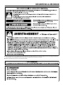
SÉCURITÉ DE LA SÉCHEUSE ............................................................ 35
OUTILS ET PIÈCES .................................................................................. 38
DIMENSIONS/DISTANCES DE DÉGAGEMENT ...................... 39
EXIGENCES D’INSTALLATION POUR LA
SÉCHEUSE À GAZ ..................................................................................... 40
EXIGENCES D’INSTALLATION POUR
LA SÉCHEUSE ÉLECTRIQUE ........................................................... 43
EXIGENCES CONCERNANT L’ÉVACUATION
DE LA SÉCHEUSE .................................................................................... 45
RACCORDEMENT À LA CANALISATION DE GAZ .................... 47
INSTALLATION DES PIEDS DE NIVELLEMENT,
DE LA GLISSIÈRE À MONNAIE ET DE LA CAISSE
À MONNAIE .................................................................................................. 49
NIVELLEMENT ..............................................................................................50
ACHEVER L’INSTALLATION ....................................................................51
INVERSION DU SENS D’OUVERTURE DE
LA PORTE ......................................................................................................... 52
INSTALLATION D’UNE CAME DE MINUTAGE
DE 30 OU 60 MINUTES ...........................................................................53
INSTRUCTIONS D’ENTRETIEN ...........................................................54
SI VOUS AVEZ BESOIN D’ASSISTANCE ........................................54
INSTRUCTIONS DE RÉGLAGE DU TABLEAU
DE COMMANDE ÉLECTRONIQUE ................................................... 55
GARANTIE .........................................................................................................61
INSTALLATION INSTRUCTIONS
CommerCial Dryer Gas or eleCtriC
INSTRUCTIONS D’INSTALLATION
séCheuse à usaGe CommerCial à Gaz ou éleCtrique

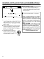
2
DRYER SAFETY
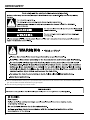
■ It is recommended that the owner post, in a prominent location, instructions for the customer’s use in the event the customer smells
gas. This information should be obtained from your gas supplier.
■ Post the following warning in a prominent location.

3
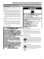
DRYER SAFETY
IMPORTANT: When discarding or storing your old clothes dryer, remove the door.

4
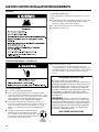
DRYER SAFETY
■ Clean dryer lint screen before or after each load.
■ Do not use this dryer without the lint screen in place.
■ Do not repair or replace any part of the dryer or attempt any
servicing unless specifically recommended in this Installation
Instructions or in published user-repair instructions that you
understand and have the skills to carry out.
■ Do not use fabric softeners or products to eliminate static
unless recommended by the manufacturer of the fabric
softener or product.
■ Do not use heat to dry articles containing foam rubber or
similarly textured rubber-like materials.
■ The final part of a tumble dryer cycle occurs without heat
(cool-down cycle) to ensure that the articles are left at a
temperature that ensures that the items will not be damaged.
■ WARNING: Never stop a tumble dryer before the end of
the drying cycle unless all items are quickly removed and
spread out so that the heat is dissipated. (Avoids risk of
spontaneous combustion).
■ Keep area around the exhaust opening and adjacent
surrounding areas free from the accumulation of lint, dust,
and dirt.
■ The interior of the dryer and dryer exhaust vent should be
cleaned periodically by qualified service personnel.
■ See “Electrical Requirements” section for grounding
instructions.
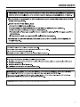
IMPORTANT SAFETY INSTRUCTIONS
WARNING: To reduce the risk of fire, electric shock, or injury to persons when using the dryer, follow basic precautions,
including the following:
SAVE THESE INSTRUCTIONS
■ Read all instructions before using the dryer.
■ This dryer is intended only for drying clothes and textiles
that have been washed in water. Do not use for any other
purpose.
■ WARNING: If you smell gas, do not use the dryer or any
electrical equipment nearby. Warn other people to clear the
area. Contact the dryer owner immediately.
■ Do not place items exposed to cooking oils in your dryer.
Items contaminated with cooking oils may contribute to a
chemical reaction that could cause a load to catch fire.
■ Do not dry articles that have been previously cleaned in,
washed in, soaked in, or spotted with gasoline, dry-cleaning
solvents, other flammable, or explosive substances as they
give off vapors that could ignite or explode.
■ Do not dry unwashed items in the dryer.
■ Do not allow children to play on or in the dryer. Close
supervision of children is necessary when the dryer is used
near children.
■ Before the dryer is removed from service or discarded,
remove the door to the dryer compartment.
■ Do not reach into the dryer if the drum is moving.
■ Do not open door while dryer is in operation. It will stop.
■ Do not install or store the dryer where it will be exposed to
the weather.
■ Do not tamper with controls.

5
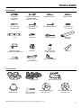
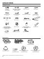
Tools Needed:
8" (203 mm) 8" (203 mm) or 10" (254 mm) Flat-Blade Screwdriver Phillips Screwdriver
or 10" (254 mm) Adjustable Wrench
Pipe Wrench that opens to 1" (25 mm)
Torx
®†
T-20 Security 1" (25 mm) Hex-Head 5⁄16" (8 mm) Socket Wrench Pliers (that open to
Screwdriver or Bit Socket Wrench 1
9
/
16
" [39 mm])
Level Utility Knife 1/4" (6 mm) Nut Driver 27" (686 mm)
Wood Block
Caulk Gun and Caulk Vent Clamps Pipe-Joint Compound Putty Knife
(for installing new exhaust vent) Suitable for Gas Type
Flashlight (optional) 1" (25 mm) Ruler or Measuring Tape
Open-End Wrenches
TOOLS & PARTS
Parts Supplied:
Foot Boots (4) Leveling Legs (4) Bezel Kit (PR models only)
Security Cone 5/16" Hex Head – 3-Pin 60-Minute Timing Cam 6-Pin 30-Minute Timing Cam
(PD models only) 18 x 2
1
⁄2" Security Bolt (CS models only) (CS models only)
(PD models only)
†® TORX and T25 are registered trademarks of Acument Intellectual Properties, LLC.

6
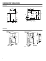
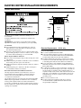
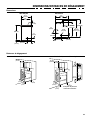
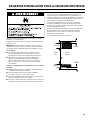
DIMENSIONS/CLEARANCES
Side View Back View
Dimensions
Clearances
29
1
/4"
(743 mm)
35"
(889 mm)
8
1
/4"
(210 mm)
1"
(25 mm)
26"
(660 mm)
3
1
/4"
(83 mm)
7
1
/2"
(191 mm)
0"
(0 mm)
0"
(0 mm)
15"
(381 mm)
14" max
(356 mm)
0"
(0 mm)
1
1
/2"
(38 mm)
5
1
/2"
(140 mm)
10
3
/4
"
(273 mm)
37
1
/2"
(953 mm)
(gas models)
41"
(1042 mm)
13
1
/2"
(343 mm)
Electric
Gas
27"
(686 mm)
3
1
/4"
(83 mm)
36"
(914 mm)
(electric models)
4" dia
(102 mm)
13
1
/2"
(343 mm)
Front View, Recessed Opening Side View, Recessed In Closet
0"
(0 mm)
14" max
(356 mm)
0"
(0 mm)
1"
(25 mm)
3"/3"
(76 mm)
3"/3"
(76 mm)
48"
2
/48"
2
(310 cm
2
)
24"
2/
24"
2
(155 cm
2
)
15"
(381 mm)
Closet Door to
Front of Dryer

7
Your dryer can be installed in a basement, laundry room, or
recessed area.
Companion appliance location requirements should also be
considered.
IMPORTANT: Do not install or store the dryer where it will be
exposed to the weather. Proper installation is your responsibility.
You will need:
■ A grounded electrical outlet located within 6 ft. (1.8 m) of
where the power cord is attached to the back of the dryer.
See “Electrical Requirements.”
■ A level floor with a maximum slope of 1" (25 mm) under entire
dryer. Installing the dryer on soft floor surfaces, such as carpets
or surfaces with foam backing, is not recommended.
Gas dryer installation clearances
■ The location must be large enough to allow the dryer door
to be fully opened.
■ Additional spacing should be considered for ease of installation
and servicing. The door opens more than 180°.
■ Additional clearances might be required for wall, door, and floor
moldings.
■ Additional spacing of 1" (25 mm) on all sides of the dryer
is recommended to reduce noise transfer.
When installing a gas dryer:
IMPORTANT: Observe all governing codes and ordinances.
■ Check code requirements: Some codes limit or do not
permit installation of clothes dryers in garages, closets,
or sleeping quarters. Contact your local building inspector.
■ Make sure that lower edges of the cabinet, plus the back and
bottom sides of the dryer, are free of obstructions to permit
adequate clearance of air openings for combustion air. See
“Recessed Area and Closet Installation Instructions” below for
minimum spacing requirements.
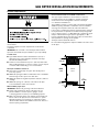
Location Requirements
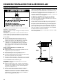
GAS DRYER INSTALLATION REQUIREMENTS
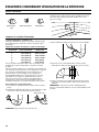
Recessed Area and Closet Installation Instructions
This dryer may be installed in a recessed area or closet. For
recessed area and closet installations, minimum clearances
can be found on the warning label on the rear of the dryer
or in “Dimensions/Clearances.”
The installation spacing is in inches and is the minimum allowable.
Additional spacing should be considered for ease of installation,
servicing, and compliance with local codes and ordinances.
If closet door is installed, the minimum unobstructed air opening in
the top and bottom is required. The unobstructed opening needs
to be 1 square inch per 1,000 Btu (252 kcal) of gas burner output.
Output on North American gas dryers is typically 22,000 Btu;
however, Canadian dryers may have lower output. Louvered doors
with equivalent air openings are acceptable.
The dryer must be exhausted outdoors.
No other fuel-burning appliance may be installed in the same closet
as the dryer.
24 in.
2
(155 cm
2
)
48 in.
2
(310 cm
2
)
3"
(76 mm)
3"
(76 mm)
Closet
door
Front
View
Closet
Door
Front
View

8
Gas Dryer Grounding
IMPORTANT: The dryer must be electrically grounded in
accordance with local codes and ordinances or, in the absence
of local codes, with the National Electrical Code, ANSI/NFPA 70,
latest edition, or Canadian Electrical Code, CSA C22.1. If codes
permit and a separate ground wire is used, it is recommended that
a qualified electrical installer determine that the ground path is
adequate.
A copy of the above code standards can be obtained from:
National Fire Protection Association
One Batterymarch Park, Quincy, MA 02269
CSA International
8501 East Pleasant Valley Road
Cleveland, Ohio 44131-5575
■ Do not ground to a gas pipe.
■ Do not have a fuse in the neutral or ground circuit.
■ A 120 volt, 60 Hz, AC only, 15- or 20-amp, fused electrical
circuit is required. A time-delay fuse or circuit breaker is also
recommended. It is recommended that a separate circuit
serving only this dryer be provided.
■ This dryer is equipped with a power supply cord having a
3-prong grounding plug.
■ To minimize the possibility of shock, the cord must be plugged
into a mating, 3 prong, grounding-type outlet, grounded in
accordance with local codes and ordinances. If a mating outlet
is not available, it is the personal responsibility and obligation of
the customer to have the properly grounded outlet installed by
a qualified electrician.
■ If codes permit and a separate ground wire is used, it is
recommended that a qualified electrician determine that the
ground path is adequate.
■ Check with a qualified electrician if you are not sure the dryer is
properly grounded.
GAS DRYER INSTALLATION REQUIREMENTS
Electrical Requirements

9
IMPORTANT: Observe all governing codes and ordinances.
This installation must conform with all local codes and ordinances.
In the absence of local codes, installation must conform with
American National Standard, National Fuel Gas Code ANSI
Z223.1/NFPA 54 or CAN/CSA B149.
A copy of the above code standards can be obtained from:
National Fire Protection Association
One Batterymarch Park, Quincy, MA 02269
CSA International
8501 East Pleasant Valley Road
Cleveland, Ohio 44131-5575
The design of this dryer has been certified by CSA International
for use at altitudes up to 10,000 feet (3048 m) above sea level at
the B.T.U. rating indicated on the model/serial plate. Burner input
adjustments are not required when the dryer is operated up to this
elevation.
When installed above 10,000 feet (3048 m), a four percent (4%)
reduction of the burner B.T.U. rating shown on the model/serial
plate is required for each 1,000 foot (305 m) increase in elevation.
For assistance when converting to other gas types and/or installing
above 10,000 feet (3048 m) elevation, contact your local service
company.
Gas Supply
GAS DRYER INSTALLATION REQUIREMENTS

10
Your dryer can be installed in a basement, laundry room, or
recessed area.
Companion appliance location requirements should also be
considered.
IMPORTANT: Do not install or store the dryer where it will be
exposed to the weather. Proper installation is your responsibility.
You will need:
■ A grounded electrical outlet located within 6 ft. (1.8 m) of
where the power cord is attached to the back of the dryer.
See “Electrical Requirements.”
■ A level floor with a maximum slope of 1" (25 mm) under entire
dryer. Installing the dryer on soft floor surfaces, such as carpets
or surfaces with foam backing, is not recommended.
Electric dryer installation clearances
■ The location must be large enough to allow the dryer door to be
fully opened.
■ Additional spacing should be considered for ease of installation
and servicing. The door opens more than 180°.
■ Additional clearances might be required for wall, door, and floor
moldings.
■ Additional spacing of 1" (25 mm) on all sides of the dryer is
recommended to reduce noise transfer.
Recessed Area and Closet Installation Instructions
This dryer may be installed in a recessed area or closet. For
recessed area and closet installations, minimum clearances
can be found on the warning label on the rear of the dryer
or in “Dimensions/Clearances.”
The installation spacing is in inches and is the minimum allowable.
Additional spacing should be considered for ease of installation,
servicing, and compliance with local codes and ordinances.
If closet door is installed, the minimum unobstructed air opening in
the top and bottom is required. Louvered doors with equivalent air
openings are acceptable.
Location Requirements
The dryer must be exhausted outdoors.
24 in.
2
(155 cm
2
)
48 in.
2
(310 cm
2
)
3"
(76 mm)
3"
(76 mm
)
Closet
door
Front
View
ELECTRIC DRYER INSTALLATION REQUIREMENTS
Closet
Door
Front
View
Electrical Requirements – U.S.A. only
It is your responsibility:
■ To contact a qualified electrical installer.
■ To be sure that the electrical connection is adequate and in
conformance with the National Electrical Code, ANSI/NFPA
70-latest edition and all local codes and ordinances.
■ The National Electrical Code requires a 4-wire power supply
connection for homes built after 1996, dryer circuits involved
in remodeling after 1996, and all mobile home installations.
■ A copy of the above code standards can be obtained from:
National Fire Protection Association, One Batterymarch Park,
Quincy, MA 02269.
■ To supply the required 3 or 4 wire, single phase, 120/240 volt,
60 Hz., AC only electrical supply (or 3 or 4 wire, 120/208 volt
electrical supply, if specified on the serial/rating plate) on a
separate 30-amp circuit, fused on both sides of the line. A time
delay fuse or circuit breaker is recommended. Connect to an
individual branch circuit. Do not have a fuse in the neutral or
grounding circuit.
■ Do not use an extension cord.
■ If codes permit and a separate ground wire is used, it is
recommended that a qualified electrician determine that
the ground path is adequate.

11
Electrical Requirements – U.S.A. only (cont.)
Electrical Connection
To properly install your dryer, you must determine the type of
electrical connection you will be using and follow the instructions
provided for it here.
■ This dryer is manufactured ready to install with a 3-wire
electrical supply connection. The neutral ground conductor is
permanently connected to the neutral conductor (white wire)
within the dryer. If the dryer is installed with a 4-wire electrical
supply connection, the neutral ground conductor must be
removed from the external ground connector (green screw),
and secured under the neutral terminal (center or white wire)
of the terminal block. When the neutral ground conductor is
secured under the neutral terminal (center or white wire) of the
terminal block, the dryer cabinet is isolated from the neutral
conductor.
■ If local codes do not permit the connection of a neutral ground
wire to the neutral wire, see “Optional 3-wire connection”
section.
■ A 4-wire power supply connection must be used when the
appliance is installed in a location where grounding through
the neutral conductor is prohibited. Grounding through the
neutral is prohibited for (1) new branch-circuit installations
and (2) areas where local codes prohibit grounding through
the neutral conductor.
Electric Dryer Power Supply Cord
If using a power supply cord:
Use a UL listed power supply cord kit marked for use with clothes
dryers. The kit should contain:
■ A UL listed 30-amp power supply cord, rated 120/240 volt
minimum. The cord should be type SRD or SRDT and be at
least 4 ft. (1.22 m) long. The wires that connect to the dryer
must end in ring terminals or “U” shaped spade terminals with
upturned ends.
■ A UL listed strain relief.
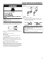
If your outlet looks like this:
4-Wire
Receptacle
(14-30R)
3-Wire
Receptacle
(10-30R)
Then choose a 4-wire power supply cord with ring or
spade terminals and UL listed strain relief. The 4-wire
power supply cord, at least 4 ft. (1.22 m) long, must
have four 10-gauge copper wires and match a 4-wire
receptacle of NEMA Type 14-30R. The ground wire
(ground conductor) may be either green or bare.
The neutral conductor must be identified by a white
cover.
Then choose a 3-wire power supply cord with ring
or spade terminals and UL listed strain relief. The
3-wire power supply cord, at least 4 ft. (1.22 m) long,
must have three 10-gauge copper wires and match a
3-wire receptacle of NEMA Type 10-30R.
If your outlet looks like this:
ELECTRIC DRYER INSTALLATION REQUIREMENTS
Electric Dryer Grounding

12
Direct Wire
If connecting by direct wire:
Power supply cable must match power supply (4-wire or 3-wire)
and be:
■ Flexible armored cable or nonmetallic sheathed copper cable
(with ground wire), covered with flexible metallic conduit.
All current-carrying wires must be insulated.
■ 10-gauge solid copper wire (do not use aluminum).
■ At least 5 ft. (1.52 m) long.
ELECTRIC DRYER INSTALLATION REQUIREMENTS
Electrical Requirements – Canada only
It is your responsibility:
■ To contact a qualified electrical installer.
■ To be sure that the electrical connection is adequate and in
conformance with the Canadian Electrical Code, C22.1 – latest
edition and all local codes. A copy of the above codes standard
may be obtained from: Canadian Standards Association,
178 Rexdale Blvd., Toronto, ON M9W 1R3 CANADA.
■ To supply the required 4 wire, single phase, 120/240 volt,
60 Hz., AC only electrical supply on a separate 30-amp circuit,
fused on both sides of the line. A time-delay fuse or circuit
breaker is recommended. Connect to an individual branch
circuit.
■ This dryer is equipped with a CSA International
Certified Power Cord intended to be plugged
into a standard 14-30R wall receptacle. The cord
is 5 ft (1.52 m) in length. Be sure wall receptacle
is within reach of dryer’s final location.
■ Do not use an extension cord.
If you are using a replacement power supply cord, it is
recommended that you use Power Supply Cord Replacement
Part Number 9831317. For further information, please reference
the service numbers located in the “Assistance or Service”
section.
4-Wire
Receptacle
(14-30R)
GROUNDING INSTRUCTIONS
SAVE THESE INSTRUCTIONS
■
For a grounded, cord-connected dryer:
This dryer must be grounded. In the event of malfunction or
breakdown, grounding will reduce the risk of electric shock
by providing a path of least resistance for electric current.
This dryer is equipped with a cord having an equipment-
grounding conductor and a grounding plug. The plug must
be plugged into an appropriate outlet that is properly
installed and grounded in accordance with all local codes
and ordinances.
WARNING: Improper connection of the equipment-
grounding conductor can result in a risk of electric shock.
Check with a qualied electrician or service representative
or personnel if you are in doubt as to whether the dryer is
properly grounded. Do not modify the plug provided with
the dryer: if it will not t the outlet, have a proper outlet
installed by a qualied electrician.

13
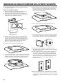
DRYER VENTING REQUIREMENTS
WARNING: To reduce the risk of fire, this dryer MUST BE
EXHAUSTED OUTDOORS.
IMPORTANT: Observe all governing codes and ordinances.
Dryer exhaust must not be connected into any gas vent, chimney,
wall, ceiling, attic, crawlspace, or a concealed space of a building.
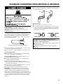
Only rigid or flexible metal vent shall be used for exhausting.
■ Only a 4" (102 mm) heavy, metal exhaust vent and clamps may
be used.
■ Do not use plastic or metal foil vent.
Rigid metal vent:
■ Recommended for best drying performance and to avoid
crushing and kinking.
Flexible metal vent: (Acceptable only if accessible to clean)
■ Must be fully extended and supported in final dryer location.
■ Remove excess to avoid sagging and kinking that may result in
reduced airflow and poor performance.
■ Do not install in enclosed walls, ceilings, or floors.
■ The total length should not exceed 7
3
⁄
4
ft. (2.4 m).
NOTE: If using an existing vent system, clean lint from entire length
of the system and make sure exhaust hood is not plugged with
lint. Replace plastic or metal foil vents with rigid metal or flexible
metal vents. Review “Vent System Chart” and if necessary, modify
existing vent system to achieve best drying performance.
4"
(102 mm)
4" (102 mm) Heavy, Metal Exhaust Vent
Elbows:
■ 45° elbows provide better airflow than 90° elbows.
Clamps:
■ Use clamps to seal all joints.
■ Exhaust vent must not be connected or secured with screws
or other fastening devices that extend into interior of duct and
catch lint. Do not use duct tape.
Improper venting can cause moisture and lint to collect
indoors, which may result in:
Moisture damage to woodwork, furniture, paint, wallpaper,
carpets, etc.
Housecleaning problems and health problems.
Better
Good

14
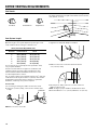
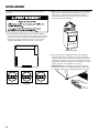
4" (102 mm) Diameter Exhaust Hoods
Box Hood Louvered Hood Angled Hood
Vent Hoods
DRYER VENTING REQUIREMENTS
Exhaust hood must be at least 12" (305 mm) from the ground or
any object that may be in the path of the exhaust (such as flowers,
rocks, bushes, or snow).
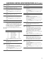
Maximum Vent Length/Vent Connection
Maximum length of vent system depends upon the type of vent
used, number of elbows, and type of exhaust hood.
Vent System Chart (Rigid Metal Vent)
No. of Box and Angled
90˚ Turns Louvered Hood Hood
0 64 ft. (19.5 m) 58 ft. (17.7 m)
1 54 ft. (16.5 m) 48 ft. (14.6 m)
2 44 ft. (13.4 m) 38 ft. (11.6 m)
3 35 ft. (10.7 m) 29 ft. (8.8 m)
4 27 ft. (8.2 m) 21 ft. (6.4 m)
For vent systems not covered by the vent specification chart,
see your parts distributor.
Provision must be made for enough air for combustion and
ventilation. (Check governing codes and ordinances.) See
“Recessed Area and Closet Installation Instructions” in the
“Location Requirements” sections.
A 4" (102 mm) outlet hood is preferred. However, a 2
1
⁄
2
" (64 mm)
outlet exhaust hood may be used. A 2
1
⁄
2
" (64 mm) outlet creates
greater back pressure than other hood types. For permanent
installation, a stationary vent system is required.
Connect Vent
1. If connecting to existing vent, make sure the vent is clean.
2. Using a 4" (102 mm) clamp, connect vent to exhaust outlet
in dryer.
NOTE: Do not remove vent collar.
Vent System Length
3. Tighten hose clamp with Phillips screwdriver.
4. Make sure the vent is secured to exhaust hood with
a 4" (102 mm) clamp.
5. Move dryer into final position. Do not crush or kink vent.
Make sure dryer is level.
NOTE: Testing for proper ventilation should be done with a
Manometer. Minimum: 0.01" (0.2 mm). Maximum: 0.6" (16 mm).
12" min.
(305 mm)
Vent Collar

15
DRYER VENTING REQUIREMENTS
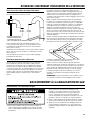
1. Connect gas supply to dryer. Use a pipe thread compound
approved for the type of gas supplied. If flexible metal tubing
is used, be certain there are no kinks.
If necessary for service, open the toe panel. Use a putty knife
to press on the toe panel lock located at the center top of the
toe panel. Pull downward on the toe panel to open. Toe panel
is hinged at the bottom.
2. Open the shut-off valve in the gas supply line and make sure
the dryer has its own gas supply opened.
3. Test all connections by brushing on an approved noncorrosive
leak-detection solution. Bubbles will show a leak. Correct any
leaks found.
Make Gas Connection
GAS SUPPLY CONNECTION
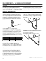
The outside end of main vent should have a sweep elbow directed
downward.
If main vent travels vertically through the roof, rather than through
wall, install a 180° sweep elbow on end of vent at least 2 ft.
(610 mm) above surface of roof.
The opening in wall or roof shall have a diameter 1⁄2" (13 mm)
larger than vent diameter. Vent should be centered in opening.
Do not install screening over end of vent for best performance.
12" min.
(305 mm)*
A main vent can be used for venting a group of dryers. The main
vent should be sized to remove 5663 l/min. (200 CFM) of air per
dryer. Large-capacity lint screens of proper design may be used in
main vent if checked and cleaned frequently. The room where the
dryers are located should have make-up air equal to or greater than
CFM of all the dryers in the room.
If an Exhaust Hood Cannot be Used
Multiple Dryer Venting
24" min.
(610 mm)
* Minimum clearance above any
accumulation of snow, ice, or
debris such as leaves
30˚ max.
Air ow
Air Flow
Back-draft dampers are available from your distributor and should
be installed in the vent of each dryer to keep exhausted air from
returning into dryers and to keep exhaust in balance within main
vent. Unobstructed return air openings are required.
Although usually each single-load dryer should have an
unobstructed outdoor air opening of 24 in.
2
(154 cm
2
) (based
on 1 in.
2
[6.5 cm
2
] per 1,000 Btu [252 kcal]), common make-up air
openings are also acceptable. Set up common openings so
the make-up air is distributed equally to all of the dryers. Keep
in mind that the coverage area must be increased by 33% to
account for the use of registers or louvers over the openings.
Also, make-up air openings should not be installed near the
location where exhaust vents exit the building.
Each vent should enter the main vent at an angle pointing in
the direction of the airflow. Vents entering from the opposite side
should be staggered to reduce the exhausted air from interfering
with the other vents.
The maximum angle of each vent entering the main vent should be
no more than 30°.
Keep air openings free of dry cleaning fluid fumes. Fumes create
acids which, when drawn through the dryer heating units, can
damage dryers and items being dried.
A clean-out cover should be located on the main vent for periodic
cleaning of the vent system.
NOTE: For more dryer venting information, please refer to
Whirlpool document W10100920.

16
This dryer is equipped for use with natural gas. It is design-certified
by CSA International for LP (propane and butane) gases with
appropriate conversion. No attempt shall be made to convert dryer
from gas specified on serial/rating plate for use with a different gas
without consulting the serving gas supplier. Conversion must be
done by a qualified service technician.
Gas conversion kit part numbers are listed near gas valve
burner base.
Type of Gas
GAS SUPPLY CONNECTION
Recommended Method
Provide a gas supply line of 1⁄2" (13 mm) rigid (IPS) pipe to dryer
location. Pipe joint compounds that resist action of LP gas must be
used. Do not use TEFLON
®†
tape. With LP gas, piping or tubing
size can be 1⁄2" (13 mm) minimum. Usually, LP gas suppliers
determine size and materials used in the system.
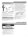
Gas Supply Pressure Testing
A 1/8" (3 mm) NPT minimum plugged tapping, accessible for
gauge testing, must be installed immediately downstream of the
installed shut-off valve to the dryer (as shown above). The dryer
must be disconnected from the gas supply piping system during
any pressure testing of the system at test pressures in excess of
1/2" psig (352 kg/m
2
). The expected pressures for the gas supply
are listed in inches of water in the table below:
Natural Gas LP Gas
Minimum
5.2" (132.1 mm) 8.0" (203.2 mm)
Maximum
10.5" (266.7 mm) 13.0" (330.2 mm)
Alternate Method
The gas supply may also be connected using 3⁄8" (10 mm)
approved copper or aluminum tubing. If the total length of
the supply line is more than 20 ft. (6.1 m), larger tubing will
be required.
If using natural gas, do not use copper tubing. Pipe joint
compounds that resist action of type of gas supplied must
be used.
Shut-off valve required
The supply line must be equipped with a manual shut-off valve
installed within 6 ft. (1.8 m) of dryer in accordance with National
Fuel Gas Code, ANSI Z223.1. This valve should be located in
same room as dryer. It should be in a location that allows ease
of opening and closing. Do not block access to shut-off valve.
In Canada, an individual manual shut-off valve must be installed
in accordance with the B149 installation codes CAN/CGA
B149.1 and CAN/CGA B149.2.
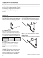
Gas Supply Line
Flexible Metal Appliance Connector
It is recommended that a new flexible stainless steel gas line,
design-certified by CSA International, be used for connecting the
dryer to the gas supply line. (The gas pipe which extends through
the lower rear of the dryer is provided with 3/8" [10 mm] male
pipe thread.)
NOTE: Do not kink or damage the flexible stainless steel gas line
when moving the dryer.
Rigid Pipe Connection
The rigid pipe connection requires a combination of pipe fittings to
obtain an in-line connection to the dryer.
†®TEFLON is a registered trademark of Chemours.

17
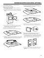
INSTALLING LEVELING LEGS, COIN SLIDE, AND COIN BOX
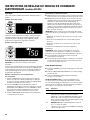
On some models: The console houses the electronic control
board. The board is factory set for a dry time of 5 minutes. Consult
the tech sheet found inside the dryer toe panel to reset dry time
and for other options.
The card reading mechanism is not included, but is available from
your usual industry sources.
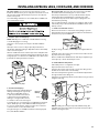
1. Prepare dryer for leveling legs
NOTE: Slide dryer onto cardboard or hardboard before moving
to avoid damaging floor covering.
Using two or more people, move dryer to desired installation
location.
Take tape off front corners of dryer. Open dryer and remove
the literature and parts packages. Wipe drum interior with a damp
cloth to remove any dust.
Take two cardboard corners from the dryer carton and place them
on the floor in back of the dryer. Firmly grasp the body of the dryer
and gently lay it on its back on the cardboard corners. Disconnect
power before making electrical connections.
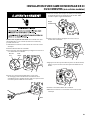
2. Screw in leveling legs
Examine leveling legs and find diamond
marking. Screw legs into leg holes by
hand. Use an adjustable wrench or
1" (25 mm) hex-head socket wrench
to finish turning legs until diamond
marking is no longer visible. Then fit
a covered foot boot over each leg foot.
To protect the floor, use a large piece of cardboard from the dryer
carton. Stand dryer up on the cardboard. Slide the dryer until
it is close to its final location. Leave enough room for electrical
connection and to connect the exhaust vent.
A longer leveling foot is available if needed on extremely sloped
floors, Part Number 279810.
Foot
Diamond
Marking
(appearance may vary)
1. Install coin slide and coin box
Remove the service door of the meter case by lifting it up at the
back. Install the money-accepting device. (Refer to manufacturer’s
instructions for proper installation.)
For dryers using coin slides, use the adapter kit supplied with the
dryer.
Install the meter case service door. Put the coin box with lock and
key in the meter case opening.
Remove cardboard or hardboard from under dryer. Adjust the legs
of the dryer up or down until the dryer is level.
2. Install added security device
Check that power is not supplied to the dryer.
Open and remove the service door.
Insert the narrow part of the security cone into the oblong hole in
the bottom rear of the meter case assembly.
Pass the security bolt through this cone and thread it by hand into
the cage nut below the oblong hole.
Tighten the security bolt by hand a few turns before using a wrench
to tighten until snug.
security
bolt
security
cone
cage nut
NOTE: Installing the security bolt provides added security, but
will add to the service time when the top needs to be removed or
lifted for servicing the dryer.
Security
Bolt
Security
Cone
Cage
Nut
On some models: The meter case houses the factory-installed
accumulator timer with actuating arm or service switch.
The factory-installed timer is set to provide 45 minutes (4 pins)
of drying time when activated by the coin slide. Timer cams
for 30-minute (6 pins) and 60-minute (3 pins) drying times are
included in the parts bag.
The coin slide mechanism, service door lock and key, and coin box
lock and key may not be included but are available from the usual
industry sources.

18
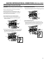
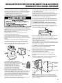
ELECTRIC DRYER ELECTRICAL CONNECTIONS (FOR U.S.A. ONLY)
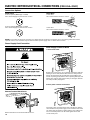
2. Insert power cord into strain relief.
Remove Terminal Block Cover
Power Supply Cord Connection
Remove hold-down screw and terminal block cover.
Put power supply cord through the strain relief. Be sure that the
wire insulation on the power supply cord is inside the strain relief.
The strain relief should have a tight fit with the dryer cabinet and
be in a horizontal position. Do not further tighten strain relief
screws at this point.
Power Cord
4-wire receptacle (NEMA Type 14-30R)
Go to "Power Supply Cord Connection" section.
3-wire receptacle (NEMA Type 10-30R)
Go to "Power Supply Cord Connection" section.
Connection Options
Direct Wire
4-wire direct
Go to "Direct Wire Connection" section.
3-wire direct
Go to "Direct Wire Connection" section.
1"
(25 mm)
5"
(127 mm)
NOTE: If local codes do not permit connection of a cabinet-ground conductor to neutral wire, go to “Connecting 3-Wire Connection:
Optional” section. This connection may be used with either a power supply cord or a direct wire connection.
Remove the screws from a ¾" (19 mm) UL listed strain relief (UL
marking on strain relief). Put the tabs of the two clamp sections
(C) into the hole below the terminal block opening (B) so that
one tab is pointing up (A) and the other is pointing down (D), and
hold in place. Tighten strain relief screws just enough to hold the
two clamp sections (C) together.
Power Supply Cord Strain Relief
1. Insert strain relief.
A
B
C
D

19
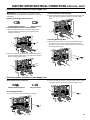
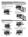
ELECTRIC DRYER ELECTRICAL CONNECTIONS (FOR U.S.A. ONLY)
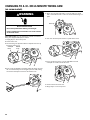
Connecting 4-Wire Connection: Power Supply Cord
Connecting 3-Wire Connection: Power Supply Cord
Standard Power Supply Cord Connectors
Flanged Spade Connector Ring Connector
Connecting Neutral Ground and Neutral Wires
1. Remove center terminal block screw (A) and the neutral
ground wire (B) by removing the green external ground
conductor screw (C).
2. Connect neutral ground wire (B) and neutral wire (white or
center wire) (D) of power supply cord under center terminal
block screw (A). Tighten screw.
Connecting Power Cord Ground Wire
3. Connect ground wire (green or bare) (E) of power supply cord
under green external ground conductor screw (C). Tighten
screw.
Connecting Remaining Wires
4. Connect remaining wires under outer terminal block screws
(F). Tighten screws. Finally, reinstall terminal block cover to
dryer rear panel. Secure cover with hold-down screw. Now go
to "Venting Requirements."
A
C
B
A
B
D
C
E
F
F
2. Connect neutral wire (white or center wire) (D) of power supply
cord under center terminal block screw (A). Tighten screw.
Standard Power Cord Connectors
Flanged Spade Connector Ring Connector
Connecting Neutral Wire
1. Loosen or remove center terminal block screw (A).
A
A
D
B
A
E
B
E
C
IMPORTANT: A 4-wire connection is required for mobile
homes and where local codes do not permit the use of 3-wire
connections.

20
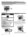
ELECTRIC DRYER ELECTRICAL CONNECTIONS (FOR U.S.A. ONLY)
F
F
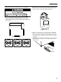
Direct Wire Connection
Remove Terminal Block Cover
Remove hold-down screw and terminal block cover.
Direct Wire Strain Relief
1. Insert strain relief.
Unscrew the removable conduit connector (A) and any
screws from a ¾" (19 mm) UL listed strain relief (UL marking
on strain relief). Put the threaded section of the strain relief (C)
through the hole below the terminal block opening (B). Reaching
inside the terminal block opening, screw the removable conduit
connector (A) onto the strain relief threads.
Put direct wire cable through the strain relief. The strain relief
should have a tight fit with the dryer cabinet and be in a horizontal
position. Tighten strain relief screw against the direct wire cable.
2. Insert conduit into strain relief and tighten clamp.
A
B
C
3. Connect remaining wires under outer terminal block screws (F).
Tighten screws. Finally, reinstall terminal block cover to dryer
rear panel. Secure cover with hold-down screw. Now go to
"Venting Requirements."
Connecting 3-Wire Connection: Power Supply Cord (cont.)
La page est en cours de chargement...
La page est en cours de chargement...
La page est en cours de chargement...
La page est en cours de chargement...
La page est en cours de chargement...
La page est en cours de chargement...
La page est en cours de chargement...
La page est en cours de chargement...
La page est en cours de chargement...
La page est en cours de chargement...
La page est en cours de chargement...
La page est en cours de chargement...
La page est en cours de chargement...
La page est en cours de chargement...
La page est en cours de chargement...
La page est en cours de chargement...
La page est en cours de chargement...
La page est en cours de chargement...
La page est en cours de chargement...
La page est en cours de chargement...
La page est en cours de chargement...
La page est en cours de chargement...
La page est en cours de chargement...
La page est en cours de chargement...
La page est en cours de chargement...
La page est en cours de chargement...
La page est en cours de chargement...
La page est en cours de chargement...
La page est en cours de chargement...
La page est en cours de chargement...
La page est en cours de chargement...
La page est en cours de chargement...
La page est en cours de chargement...
La page est en cours de chargement...
La page est en cours de chargement...
La page est en cours de chargement...
La page est en cours de chargement...
La page est en cours de chargement...
La page est en cours de chargement...
La page est en cours de chargement...
La page est en cours de chargement...
La page est en cours de chargement...
La page est en cours de chargement...
La page est en cours de chargement...
-
 1
1
-
 2
2
-
 3
3
-
 4
4
-
 5
5
-
 6
6
-
 7
7
-
 8
8
-
 9
9
-
 10
10
-
 11
11
-
 12
12
-
 13
13
-
 14
14
-
 15
15
-
 16
16
-
 17
17
-
 18
18
-
 19
19
-
 20
20
-
 21
21
-
 22
22
-
 23
23
-
 24
24
-
 25
25
-
 26
26
-
 27
27
-
 28
28
-
 29
29
-
 30
30
-
 31
31
-
 32
32
-
 33
33
-
 34
34
-
 35
35
-
 36
36
-
 37
37
-
 38
38
-
 39
39
-
 40
40
-
 41
41
-
 42
42
-
 43
43
-
 44
44
-
 45
45
-
 46
46
-
 47
47
-
 48
48
-
 49
49
-
 50
50
-
 51
51
-
 52
52
-
 53
53
-
 54
54
-
 55
55
-
 56
56
-
 57
57
-
 58
58
-
 59
59
-
 60
60
-
 61
61
-
 62
62
-
 63
63
-
 64
64


Maytag MDE20CSAYW Guide d'installation
- Catégorie
- Sèche-linge électriques
- Taper
- Guide d'installation
- Ce manuel convient également à
dans d''autres langues
- English: Maytag MDE20CSAYW Installation guide