American Range NOPR30SSV Guide d'installation
- Catégorie
- Hottes
- Taper
- Guide d'installation
Ce manuel convient également à

NOPR30SS600
NOPR36SS600
Installation Instructions
Use and Care Information
Instructions d'installation
Utilisez et d'entretien
Instrucciones de instalación
Información de uso y cuidado
Nova PRO

2
READ AND SAVE THESE INSTRUCTIONS BEFORE YOU
START INSTALLING THIS RANGEHOOD
WARNING: - TO REDUCE THE RISK OF A RANGE TOP GREASE FIRE:
a) Never leave surface units unattended at high settings. Boilovers cause smoking and
greasy spillovers that may ignite. Heat oils slowly on low or medium setting.
b)AlwaysturnhoodONwhencookingathighheatorwhenambeingfood(i.e.Crepes
Suzette, Cherries Jubilee, Peppercorn Beef Flambé).
c) Clean ventilating fans frequently. Grease should not be allowed to accumulate on fan
orlter.
d) Use proper pan size. Always use cookware appropriate for the size of the surface element.
WARNING: - TO REDUCE THE RISK OF INJURY TO PERSONS IN THE EVENT OF A
RANGE TOP GREASE FIRE, OBSERVE THE FOLLOWING*:
a)SMOTHERFLAMESwithaclose-ttinglid,cookiesheet,ormetaltray,thenturnofftheburner.
BECAREFULTOPREVENTBURNS.IftheamesdonotgooutimmediatelyEVACUATE
AND CALL THE FIRE DEPARTMENT.
b) NEVER PICK UP A FLAMING PAN - You may be burned.
c) DO NOT USE WATER, including wet dishcloths or towels - a violent steam explosion will
result.
d) Use an extinguisher ONLY if:
1. You know you have a Class ABC extinguisher, and you already know how to operate it.
2. Thereissmallandcontainedintheareawhereitstarted.
3. Theredepartmentisbeingcalled.
4. Youcanghttherewithyourbacktoanexit.
* Based on "Kitchen Firesafety Tips" published by NFPA
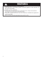
WARNING - TO REDUCE THE RISK OF FIRE OR ELECTRIC SHOCK, do not use this fan
with any solid-state speed control device.
WARNING - TO REDUCE THE RISK OF FIRE, ELECTRICAL SHOCK, OR INJURY TO
PERSONS, OBSERVE THE FOLLOWING:
1. Use this unit only in the manner intended by the manufacturer. If you have any
questions, contact the manufacturer.
2. Before servicing or cleaning unit, switch power off at service panel and lock the
service disconnecting means to prevent power from being switched on acciden-
tally. When the service disconnecting means cannot be locked, securely fasten a
prominent warning device, such as a tag, to the service panel.
CAUTION: For General Ventilating Use Only. Do Not Use To Exhaust Hazardous or
Explosive Materials and Vapors.
WARNING - TO REDUCE THE RISK OF FIRE, ELECTRICAL SHOCK, OR INJURY TO
PERSONS, OBSERVE THE FOLLOWING:
1. InstallationWorkAndElectricalWiringMustBeDoneByQualiedPerson(s)InAccor-
dance With All Applicable Codes And Standards, Including Fire-Rated Construction.
2. Sufcient airisneededfor propercombustion andexhausting ofgases through
theue(chimney) offuelburningequipmenttopreventbackdrafting.Followthe
heating equipment manufacturer's guideline and safety standards such as those
publishedbytheNational Fire ProtectionAssociation (NFPA),and theAmerican
SocietyforHeating,RefrigerationandAirConditioningEngineers(ASHRAE),and
the local code authorities.

3
ALL WALL AND FLOOR OPENINGS WHERE THE RANGEHOOD IS INSTALLED MUST
BE SEALED.
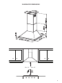
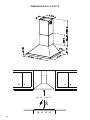
This rangehood requires at least 24" of clearance between the bottom of the rangehood and the
cooking surface or countertop. This hood has been approved by UL at this distance from the cooktop.
This minimum clearance may be higher depending on local building codes. For gas cooktops and
combination ranges, a minimum of 30" is recommended and may be required.
The maximum depth of overhead cabinets is 13". Overhead cabinets on both sides of this unit must be
a minimum of 18" above the cooking surface or countertop. Consult the cooktop or range installation
instructions given by the manufacturer before making any cutouts.
MOBILE HOME INSTALLATION The installation of this rangehood must conform to the Manufactured
Home Construction and Safety Standards, Title 24 CFR, Part 3280 (formerly Federal Standard for
Mobile Home Construction and Safety, Title 24, HUD, Part 280). See Electrical Requirements.
• Venting system MUST terminate outside the home.
• DO NOT terminate the ductwork in an attic or other enclosed space.
• DO NOT use 4" laundry-type wall caps.
• Flexible-type ductwork is not recommended.
• DO NOT obstruct the ow of combustion and ventilation air.
• Failure to follow venting requirements may result in a re.
WARNING
!
Cold Weather installations
An additional back draft damper should be installed to minimize backward cold air ow and a nonmetal-
lic thermal break should be installed to minimize conduction of outside temperatures as part of the vent
system. The damper should be on the cold air side of the thermal break. The break should be as close
as possible to where the vent system enters the heated portion of the house.
VENTING REQUIREMENTS
Determine which venting method is best for your application. Ductwork can extend either through the
wall or the roof.
The length of the ductwork and the number of elbows should be kept to a minimum to provide efcient
performance. The size of the ductwork should be uniform. Do not install two elbows together. Use duct
tape to seal all joints in the ductwork system. Use caulking to seal exterior wall or oor opening around
the cap.
Flexible ductwork is not recommended. Flexible ductwork creates back pressure and air turbu-
lence that greatly reduces performance.
Make sure there is proper clearance within the wall or oor for exhaust duct before making cutouts. Do
not cut a joist or stud unless absolutely necessary. If a joist or stud must be cut, then a supporting frame
must be constructed.
WARNING - To Reduce The Risk Of Fire, Use Only Metal Ductwork.
CAUTION-Toreduceriskofreandtoproperlyexhaustair,besuretoductairoutside–Do
not vent exhaust air into spaces within walls or ceilings or into attics, crawl spaces, or garages.
3. When cutting or drilling into wall or ceiling, do not damage electrical wiring and
other hidden utilities.
4. Ducted fans must always be vented to the outdoors.

4
• Electrical ground is required on this rangehood.
• If cold water pipe is interrupted by plastic, nonmetallic gaskets or other materials, DO
NOT use for grounding.
• DO NOT ground to a gas pipe.
• DO NOT have a fuse in the neutral or grounding circuit. A fuse in the neutral or
grounding circuit could result in electrical shock.
• Check with a qualied electrician if you are in doubt as to whether the rangehood is
properly grounded.
• Failure to follow electrical requirements may result in a re.
WARNING
!

5
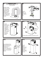
RANGEHOOD DIMENSIONS
Min. 24" Min. 30"

6
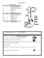
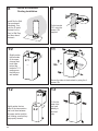
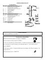
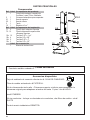
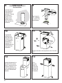
MAIN PARTS
Components
Ref. Qty. Product Components
1 1 Hood Body, complete with: Con-
trols, Lights, Filters, Blower.
2 1 Telescopic Chimney comprising:
2.1 1 Upper Section
2.2 1 Lower Section
3 1 Cover
10 1 Damper ø 5 7/8"
Ref. Qty. Installation Components
7.1 2 Hood Body Fixing Brackets
7.2.1 2 Upper Chimney Section Fixing
Brackets
12a 10 Screws 3/16" x 1 3/4"
12b 4 Screws 1/8" x 3/8"
12d 2 Screws 3/16" x 1"
12e 3 Screws 1/8" x 1/4"
Qty. Documentation
1 Instruction Manual
Available Accessories
Direct Connect Wiring Box sku # number: WIREBOX
Activated Charcoal Filter sku # FILTER1LL
High Ceiling Chimney Kit - Upper and Lower Chimney Flue to replace the original ue's
to t up to 11' ceilings - sku# HIGH3
sku# CFMRED2
Ductless Kit - Includes Ductless Diverter, Two Charcoal Filters - sku# DUCT5
Wireless Remote Control-REMCTRL
Parts needed
- 6" Round Metal ductwork .
Created by
-
Denomination
-
Lang EN
Sheet
1
/1
Modif.by
Approved by
Approval date
Doc. status
Drawing N.
NEW_DRAWING_BOX
Rev
01
1
2.2
2.1
10
7.2.1
12b
12a
12d
3

7
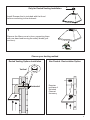
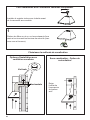
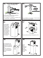
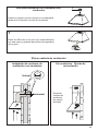
Choose your ducting method
Non Ducted - Recirculation OptionDucted Venting Options Installation
Requires
purchase of
Activated
Charcoal
Accessory
Horizontal
Vertical
6"
H
I
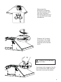
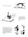
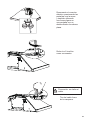
Install Damper that is included with the Hood
before connecting to the ductwork.
Only for Ducted Venting Installation
Remove the lters one at a time, supporting them
with one hand and turning the safety knobs (pull
and turn).
1

8
6"
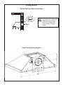
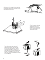
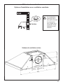
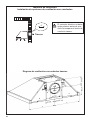
Rear
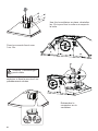
Ducted Venting Options Installation
Ducting Methods
The Electrical Connector
must be removed rst
before converting the
hood to Rear Ducting
mode.
Rear Ducted Venting diagram

9
Disconnect the
Electrical Connectors
by depressing the tabs
with your hand and
also using light force on
one tab with a at head
screwdriver.
Remove the 2 screws
as shown in the image
to the left from the top
electrical cover and set
aside.
As shown in the image to the left
pull out the loose cable with the
electrical cover and set aside.
Caution: Do not damage
the Cable.

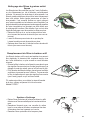
10
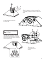
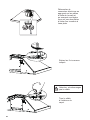
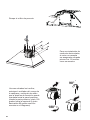
As shown in the image to the right use
a athead screwdriver to break out the
rear electrical knockout.
For a horizontal ducting
installation the motor
needs to be unsecured
by rst removing the 12
screws as shown.
Once the screws are removed,
extract the blower from the body
of the Hood and position it so the
transition opening is facing to the
rear wall (from the back remove and
rotate 180 degrees to the left, and
then ip it back 90 degrees as shown
in the diagram).

11
Once the blower is in place re-install the
12 screws to fasten the motor to the Hood
body.
Reconnect the
Connectors to the
blower.
Fix the Supplied Cover with
3 screws 12e.
As shown in the image to the right
take the cable and cover removed
previously and place back in original
position and secure with the 2 screws
removed previously.
Caution: Do not damage
the Cable.

12
2
3
´
>
x8
x8
´
´
´
´
´ ´
7.2.1
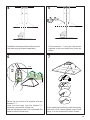
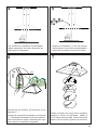
Draw a vertical line on the supporting wall as high as practical, at the center of the area in which
the hood will be installed.
Draw a horizontal line at where the bottom edge of the hood will be located as indicated in the gure
that is a minimum of 24" electric and 30" gas cooking surface clearance.
Installation Instructions
Place a Upper bracket 7.2.1 on the wall as shown about 1 1/8" from the ceiling or upper limit, aligning the
centers(notch) with the vertical reference line and mark the wall at the centers of the holes in the bracket.
Place the other bracket 7.2.1 on the wall as shown, below the rst bracket, at the height of the upper
chimney section supplied and aligning the centers(notch) with the vertical line.
Mark the wall at the centers of the holes in the bracket.
Place bracket 7.1 as shown 5” 13/16 from the vertical reference line and 7” 1/2 above the horizontal
reference line.
Mark the centers of the holes in the bracket and repeat this operation on the other side.
Drill ø 5/16" holes at all the centers points marked (point 1,2,3,4,5,6,7,8) as shown.
Fix the 2 brackets 7.2.1 using the 12a screws supplied with wall plugs (purchase separately).

13
I = 6x
4
5
6
7
12a
x2
Ø
8
mm
x2
x2
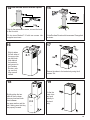
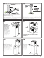
Installation screws provided must be secured
with wall plugs (purchase separately).
From inside the Hood body, mark the security
hole, drill ø 5/16" where marked, insert 2 wall
plugs 11 in the holes and x with 2 screws.
5/16"
Fix the brackets 7.1 using the 12a screws
supplied in the hood body xing holes as
shown.
Screw the two screws 12d supplied onto the
brackets 7.1.
Hook the hood body onto the bracket 7.1,
centering it around the vertical line.
Use the adjusting screws 12d underneath the
hood to level the hood body.
12a

14
2.1
2.2
8
10
11
9
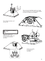
Slightly widen
the two sides
of the upper
chimney and
hook them
behind the
brackets 7.2.1,
making sure
that they are
well seated.
Secure the sides to the brackets by using the 4
screws 12b.
13
Fix the bracket
7.2.1 using the
screws 12a
supplied.
12
Slightly widen the two
sides of the lower section
and hook them between
the upper section and the
wall, making sure that they
are properly housed.
Install Roof or Wall
Cap purchased
separately. Con-
nect the 6" metal
ductwork to the
Roof or Wall Cap
and then attach
ductwork.
Vertical or Horizontal
Ducting Installation
L = 4x
12a
N = 4x
12b
2.1
Fix the the
lower chim-
ney hood
laterally to
the hood
body.

15
14
Non-Ducted Recirculation Option
Only for the recirculation version, connect the hood
to the Air outlet.
16 17
2.1
Fix the Ductless Diverter with two screws 12a supplied
as shown.
Slightly widen
the two sides of
the upper chim-
ney and hook
them behind
the brackets
and connect to
the Ductless
Diverter, mak-
ing sure that
they are well
seated.
15
12a
Fix the lower Bracket 7.2.1 with two screws 12a
supplied as shown.
N = 4x
12b
Secure the sides to the brackets by using the 4
screws 12b.
2.2
2.1
18 19
Slightly widen the two
sides of the the lower
chimney hood and hook
them between
the upper section and the
wall, making sure that they
are properly housed.
Fix the the
lower chim-
ney hood
laterally to
the hood
body .

16
22
21
Replace the metal grease lters
removed previously.
Direct Connect Wiring Box
Accessory sku # WIREBOX
(purchased separately)
Created by
-
Denomination
-
Lang EN
Sheet
1
/1
Modif.by
Approved by
Approval date
Doc. status
Drawing N.
NEW_DRAWING_BOX
Rev
01
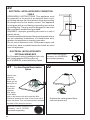
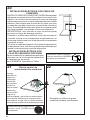
ELECTRICAL INSTALLATION WITH CONNECTION
CABLE
GROUNDING INSTRUCTIONS This appliance must
be grounded. In the event of an electrical short circuit,
grounding reduces the risk of electric shock by providing
an escape wire for the electric current. This appliance
is equipped with a cord having a grounding wire with a
grounding plug. The plug must be plugged into an outlet
that is properly installed and grounded.
WARNING - Improper grounding can result in a risk of
electric shock.
Consult a qualied electrician if the grounding instructions
are not completely understood, or if doubt exists as to
whether the appliance is properly grounded.
Do not use an extension cord. If the power supply cord
is too short, have a qualied electrician install an outlet
near the appliance.
ELECTRICAL INSTALLATION WITH
OPTIONAL WIRING BOX
For Permanent wiring Installation-Use only
with Listed rangehood Wiring Box kit
sku # WIREBOX, manufactured by Faber.
Max. 33 7/16”
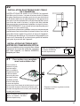
For Non-Ducted Recirculation
Option
Required Activated Charcoal Filter
Accessory - sku # - FILTER1
(purchased separately)
Attach each
charcoal
lter to the
black grid on
each side of
the blower.
Press the
charcoal
lter tightly
to the black
grid on the blower side and rotate the lter
clockwise (towards the front of the hood) until it
locks into place. Turn counterclockwise (towards
the back of the hood) to remove.
20

17
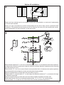
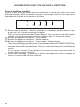
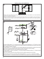
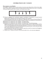
USE AND CARE INFORMATION
T1. Fan Off Button:Turn the blower Off. The fan can be operated by pressing any of the fan setting
buttons.
Hold down this button for 2 seconds to activate Delay Off function which will keep the fan On for 15
minutes and automatically shut Off.
T2. Fan Settings Buttons: Low Speed.
T3. Fan Settings Buttons: Medium Speed.
T4. Fan Settings Buttons: High Speed / Intensive Speed.
Hold down the button for 2 seconds to activate the INTENSIVE SPEED, which is timed to run for 10
minutes. At the end of this time it will automatically return to the speed set before.Suitable to deal
with maximum levels of cooking fumes.
If you hold this button down for 2 seconds when the hood is off, then after 2 minutes the motor will
shut off.
L. Light Button: Press the LIGHT button to turn the light on and again to turn off.
T1 T2 T3 T4 L
LT1 T2 T3 T4
For Best Results
Start the rangehood several minutes before cooking to develop proper airow. Allow the
rangehood to operate for several minutes after cooking is complete to clear all smoke and
odors from the kitchen.

18
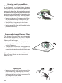
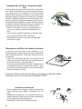
Cleaningmetalgreaselters
The lters must be cleaned every 2 months of operation,
or more frequently for particularly heavy usage, and
can be washed in a dishwasher.The metal grease lters
should be cleaned frequently in hot detergent solution or
washed in the dishwasher. Stainless steel cleaner should
be used on stainless rangehoods. Abrasives and scouring
agents can scratch stainless steel nishes and should not
be used to clean nished surface. Remove all water or
any other liquid from washing before re-installing lters.
• Remove the lters one at a time, supporting them
with one hand and turning the safety knobs (pull
and turn).
• Wash the lters, taking care not to bend them.
Allow them to dry before retting.
• Replace them and x them using the safety knobs
provided (pull and turn).
Replacing Activated Charcoal Filter
The Activated Charcoal Filters are not washable
and cannot be regenerated, and should be replaced
approximately every 4 months of operation, or more
frequently with heavy usage.
• Remove the charcoal lter by rotating it clockwise (
backwards) until it unlocks from the motor housing
and pull off sideways.
• To re-insert each charcoal lter, place up against the
side of the blower and push it inward. Then turn the
charcoal lter clockwise (forward) until it ts into place.
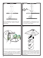
Lighting unit
• Remove the snap-on lamp cover by levering it from
under the metal ring, supporting it with one hand.
• Replace the lamp with a new one of the same type,
making sure that you insert the two pins properly into
the housings on the lamp holder.
• Replace the snap-on lamp cover.
"When used in recirculation mode, to Reduce the
Risk of Fire and Shock use only conversion kit
Model FILTER 1"

19
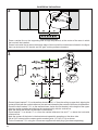
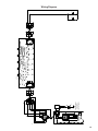
Wiring Diagram

20
January 4, 2016
FABER CONSUMER WARRANTY & SERVICE
All Faber products are warranted against any defect in materials or workmanship for the original purchaser
for a period of 1 year from the date of original purchase (requires proof of purchase). This warranty covers
labor and replacement parts. Faber, at its option, may repair or replace the product or components
necessary to restore the product to good working condition. To obtain warranty service, contact the dealer
from whom you purchased the range hood, or the local Faber distributor. If you cannot identify a local Faber
distributor, contact us at (508) 358-5353 for the name of a distributor in your area.
The following is not covered by Faber's warranty:
1. Service calls to correct the installation of your range hood, to instruct you how to use your range hood, to
replace or repair house fuses or to correct house wiring or plumbing.
2. Service calls to repair or replace range hood light bulbs, fuses or filters. Those consumable parts are
excluded from warranty coverage.
3. Repairs when your range hood is used for other than normal, single-family household use.
4. Damage resulting from accident, alteration, misuse, abuse, fire, flood, acts of God, improper installation,
installation not in accordance with electrical or plumbing codes or Faber documentation, or use of products
not approved by Faber.
5. Replacement parts or repair labor costs for units operated outside the United States or Canada, including
any non-UL or C-UL approved Faber range hoods.
6. Repairs to the hood resulting from unauthorized modifications made to the range hood.
7. Expenses for travel and transportation for product service in remote locations and pickup and delivery
charges. Faber range hoods should be serviced in the home.
THIS WARRANTY DOES NOT ALLOW RECOVERY OF INCIDENTAL OR CONSEQUENTIAL DAMAGES, INCLUDING, WITHOUT
LIMITATION, DIRECT, INDIRECT, INCIDENTAL, SPECIAL OR CONSEQUENTIAL DAMAGES, PERSONAL INJURY/WRONGFUL
DEATH OR LOST PROFITS FABER WARRANTY IS LIMITED TO THE ABOVE CONDITIONS AND TO THE WARRANTY PERIOD
SPECIFIED HEREIN AND IS EXCLUSIVE. EXCEPT AS EXPRESSLY SPECIFIED IN THIS AGREEMENT, FABER DISCLAIMS ALL
EXPRESS OR IMPLIED CONDITIONS, REPRESENTATIONS, AND WARRANTIES INCLUDING, WITHOUT LIMITATION, ANY
IMPLIED WARRANTIES OF MERCHANTABILITY OR FITNESS FOR A PARTICULAR PURPOSE
.
This warranty gives you specific legal rights that may vary from state to state.
Model#: ______________________________ Serial #: _____________________________
La page est en cours de chargement...
La page est en cours de chargement...
La page est en cours de chargement...
La page est en cours de chargement...
La page est en cours de chargement...
La page est en cours de chargement...
La page est en cours de chargement...
La page est en cours de chargement...
La page est en cours de chargement...
La page est en cours de chargement...
La page est en cours de chargement...
La page est en cours de chargement...
La page est en cours de chargement...
La page est en cours de chargement...
La page est en cours de chargement...
La page est en cours de chargement...
La page est en cours de chargement...
La page est en cours de chargement...
La page est en cours de chargement...
La page est en cours de chargement...
La page est en cours de chargement...
La page est en cours de chargement...
La page est en cours de chargement...
La page est en cours de chargement...
La page est en cours de chargement...
La page est en cours de chargement...
La page est en cours de chargement...
La page est en cours de chargement...
La page est en cours de chargement...
La page est en cours de chargement...
La page est en cours de chargement...
La page est en cours de chargement...
La page est en cours de chargement...
La page est en cours de chargement...
La page est en cours de chargement...
La page est en cours de chargement...
La page est en cours de chargement...
La page est en cours de chargement...
La page est en cours de chargement...
La page est en cours de chargement...
-
 1
1
-
 2
2
-
 3
3
-
 4
4
-
 5
5
-
 6
6
-
 7
7
-
 8
8
-
 9
9
-
 10
10
-
 11
11
-
 12
12
-
 13
13
-
 14
14
-
 15
15
-
 16
16
-
 17
17
-
 18
18
-
 19
19
-
 20
20
-
 21
21
-
 22
22
-
 23
23
-
 24
24
-
 25
25
-
 26
26
-
 27
27
-
 28
28
-
 29
29
-
 30
30
-
 31
31
-
 32
32
-
 33
33
-
 34
34
-
 35
35
-
 36
36
-
 37
37
-
 38
38
-
 39
39
-
 40
40
-
 41
41
-
 42
42
-
 43
43
-
 44
44
-
 45
45
-
 46
46
-
 47
47
-
 48
48
-
 49
49
-
 50
50
-
 51
51
-
 52
52
-
 53
53
-
 54
54
-
 55
55
-
 56
56
-
 57
57
-
 58
58
-
 59
59
-
 60
60


American Range NOPR30SSV Guide d'installation
- Catégorie
- Hottes
- Taper
- Guide d'installation
- Ce manuel convient également à
dans d''autres langues
Autres documents
-
Faber Glassy 30 SS 300 cfm Guide d'installation
-
Faber Nova Pro 30 SSV with VAM Guide d'installation
-
-
-
-
-
-
-
-