
INTRODUCTION
INTRODUCTION
INTRODUCTION | 1
INSTALLATION GUIDE
BUILT-IN UNDERCOUNTER ICE MAKER
GUIDE D’INSTALLATION
MACHINE À GLAÇONS ENCASTRÉE SOUS LE COMPTOIR
W11175865A

INTRODUCTION
2 | INTRODUCTION
SAFETY
All safety messages will tell you what the potential hazard is, tell you how to reduce the chance of injury, and tell you what can happen if the instructions are not followed.
Your safety and the safety of others are very important.
We have provided many important safety messages in this manual and on your appliance. Always read and obey all safety messages.
This is the safety alert symbol.
This symbol alerts you to potential hazards that can kill or hurt you and others.
All safety messages will follow the safety alert symbol and either the word “DANGER” or “WARNING.”
These words mean:
DANGER
WARNING
You can be killed or seriously injured if you don't immediately follow instructions.
You can be killed or seriously injured if you don't follow instructions.
IMPORTANT SAFETY INSTRUCTIONS
WARNING:
To reduce the risk of re, electric shock, or injury when using your refrigerator, follow these basic precautions:
SAVE THESE INSTRUCTIONS
■ Plug into a grounded 3 prong outlet.
■ Do not remove ground prong.
■ Do not use an adapter.
■ Do not use an extension cord.
■ Do not store explosive substances such as
aerosol cans with a flammable propellant in
this appliance.
■ Disconnect power before cleaning.
■ Disconnect power before servicing.
■ Replace all parts and panels before operating.
■
Connect to potable water supply only.
■ If the supply cord is damaged, it must be replaced
by the manufacturer, its service agent, or similarly
qualified person in order to avoid a hazard.
■ This appliance is not intended for use by persons
(including children) with reduced physical, sensory,
or mental capabilities, or lack of experience and
knowledge, unless they have been given
supervision or instruction concerning use of the
appliance by a person responsible for their safety.
■ Use two or more people to move and install
ice maker.
■ Children should be supervised to ensure that they do
not play with the appliance.
■ This appliance is intended to be used in household
and similar applications such as:
– staff kitchen areas in shops, offices, and other
working environments;
– farmhouses and by clients in hotels, motels, and
other residential-type environments;
– bed and breakfast-type environments;
– catering and similar non-retail applications.

INTRODUCTION
INTRODUCTION
REGISTERING YOUR
APPLIANCE
Gain access to our concierge-level customer support
by registering your appliance. We make product
registration simple and straightforward so that you
can start using your exclusive JennAir benets today.
Registering your appliance allows you to:
Streamline your warranty service
If we have your product information, we
can help you faster.
Protect your purchase
In case of an insurance loss, such as re,
ood, or theft, your product registration
could serve as a proof of purchase.
Keep your family safe
We’ll notify you in the rare case of a safety
notication.
Start taking advantage of these benets today by
going online to register your product at
jennair.com/customer-care.
TABLE OF CONTENTS
INTRODUCTION
PRODUCT IDENTIFICATION
Your product identication that includes the model
and serial number are listed on the product rating
plate.
Recording this information below allows us to more
easily assist you if your product shall every require
service from one of our Whirlpool Authorized Service
Providers.
Model Number: ________________________________
Serial Number: ________________________________
Date of Installation: ___________________________
Authorized Dealer: ____________________________
Authorized Dealer Phone #: ____________________
INTRODUCTION
Safety ............................................................ 2
Registering Your Appliance ........................... 3
Product Identication .................................... 3
GETTING STARTED
Before Installation .......................................... 4
Tools Required ............................................... 4
Parts Provided ............................................... 4
Vacation or Extended Time Without Use....... 5
Unpack the Ice Maker ................................... 5
Optional Personalizations .............................. 5
SITE PREPARATION
Product and Opening Dimensions ................ 6
Location Requirements ................................. 7
Electrical Requirements ................................. 8
Water Supply Requirements ..........................8
Drain Supply Requirements ........................... 9
Gravity Drain System .................................... 9
DOOR REVERSAL
Removing the Hinge Covers.......................... 10
Removing the Hinges .................................... 12
Preparing the Bottom Hinges ........................ 14
Reversing the Hinges .................................... 16
INSTALLATION
Connecting the Water Supply ....................... 18
Installing the Drain Pump .............................. 20
Connecting the Drain .................................... 26
Leveling and Securing ................................... 28
Custom Wood Panel Installation ................... 32
Installing Auxiliary Grill .................................. 34
APPENDIX
Accessories ................................................... 36
TABLE DES MATIÈRES.................39
INTRODUCTION | 3

GETTING STARTED
4 | GETTING STARTED
BEFORE INSTALLATION
Gather the required tools and parts before starting
installation. Read and follow the instructions provided
with any tools listed.
IMPORTANT: These instructions are intended
as a general guide only and do not supersede any
national or local codes in any way. Compliance
with all local, state, or national codes pertaining to
this type of installation should be determined prior to
installation.
Installer: Please be sure to leave Installation
Instructions with the homeowner.
Homeowner: Keep the Installation Instructions for
future reference.
TOOLS REQUIRED
Gather the required tools before starting installation.
Tools Required
Cordless drill and drill bits
Phillips screwdriver
Pencil
Masking tape
2 adjustable wrenches
Level
Wood screws (custom door panel)
Wood screws
2" Hole Saw or 2" Forstner bit
Double sided adhesive tape
PARTS PROVIDED
Cabinet brackets
Drain hose and clamp (in hose bag) - on
some models only
Auxiliary grill kit

GETTING STARTED | 5
GETTING STARTED
GETTING STARTED
UNPACK THE ICE MAKER
Removing Packaging Materials
Remove tape and glue from your ice maker
before using.
To remove any remaining tape or glue from
the exterior of the ice maker, rub the area
briskly with your thumb. Tape or glue residue
can also be easily removed by rubbing a
small amount of liquid dish soap over the
adhesive with your ngers. Wipe with warm
water and dry.
Do not use sharp instruments, rubbing
alcohol, ammable uids, or abrasive
cleaners to remove tape or glue. Do not
use chlorine bleach on the stainless steel
surfaces of the ice maker. These products
can damage the surface of your ice maker.
Cleaning Before Use
After you remove all of the packaging materials, clean
the inside of your ice maker before using it. See the
cleaning instructions in the “Ice Maker Care” section.
WARNING
Excessive Weight Hazard
Use two or more people to move and install
ice maker.
Failure to do so can result in back or other
injury.
VACATION OR EXTENDED
TIME WITHOUT USE
When you will not be using the ice maker for an
extended period of time, turn off the water and power
supply to the ice maker.
Check that the water supply lines are insulated
against freezing conditions. Ice formations in the
supply lines can increase water pressure and cause
damage to your ice maker or home. Damage from
freezing is not covered by the warranty.
OPTIONAL PERSONALIZATIONS
Reversing the Door
For how to reverse the door, refer the “Door Reversal”
section.
Custom Panel Installation
For instructions on how to install a custom door
panel, go to the “Custom Wood Door Panel” section.
If you plan to install a custom overlay panel, you will
need to make the panel yourself or consult a qualied
cabinetmaker or carpenter.
IMPORTANT:
The thickness of the overlay panel must be
3/4" (1.91 cm).
Overlay panel must not weigh more than
8 lbs (3.62 kg).
Overlay panels weighing more than
recommended may cause damage to your
ice maker.
Match wood grain direction with that of
adjacent cabinets.
Sand panel edges to provide a smooth
nish.
Use moisture sealer on both sides and all
edges of the panel to avoid damage from
moisture.
PARTS NEEDED:
Instructions, #8 x 1/2" pan head wood
screws (8)
Stainless Steel Panel Installation
Refer instructions received with Stainless Steel Panel
kit for panel installation.

SITE PREPARATION
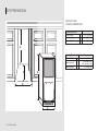
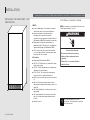
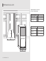
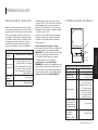
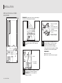
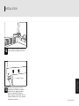
PRODUCT AND
OPENING DIMENSIONS
Product Dimensions
Product Width A 14
7
⁄
8
" (37.8 cm)
Product Height B 33
3
⁄
4
" (85.7 cm)
Product Depth (no door) C 22
1
⁄
16
" (56.1 cm)
Opening Dimensions
Opening Width D 15" (38.1 cm)
Opening Height E
34" min (86.4 cm)
34
1
⁄
2
" max (87.6 cm)
Opening Depth F 24" (60.96 cm)
D
E
F
A
B
C
SITE PREPARATION
6 | SITE PREPARATION

SITE PREPARATION | 7
SITE PREPARATION
SITE PREPARATION
A
D
C
B
LOCATION REQUIREMENTS
Installation must comply with all governing codes
and ordinances.
Temperature
It is recommended that you install the ice maker in a
well-ventilated area with temperatures above
55°F (13°C) and below 110°F (43°C). Best results are
obtained between 70°F and 90°F (21ºC and 32°C).
Location
The ice maker must be installed in an area sheltered
from the elements, such as wind, rain, or water spray.
To ensure proper ventilation for your ice maker, the
front side must be completely unobstructed. The ice
maker may be closed in on the top and three sides,
however the installation should allow the ice maker to
be pulled forward for servicing if necessary.
The auxiliary grill kit provided can be used to align
the toe grill with the rest of the cabinets while not
obstructing ventilation of the ice maker.
Floor must be able to support the ice maker’s total
weight, of more than 106 lbs (48.08 kg), including
door panels and contents of the ice maker. It is
important for the ice maker to be level in order to
work properly. If needed, you can adjust the height
of the ice maker by changing the height of the
leveling legs. The face of the cabinetry must be ush
with the front of the ice maker.
Check that the power supply cord, water supply line,
and drain line (on some models) are not damaged,
pinched, or kinked between the ice maker and the
cabinet.
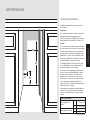
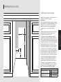
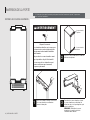
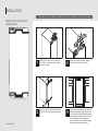
SITE PREPARATION
Utility Location Range
Power Supply Cord
Range
A 11
1
⁄
2
" (29.2 cm)
B 28
1
⁄
2
" (72.4 cm)
Water Supply Line Range
C 3
1
⁄
2
" (8.9 cm)
D 9" (22.9 cm)

8 | SITE PREPARATION
SITE PREPARATION
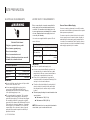
ELECTRICAL REQUIREMENTS
Electrical Requirements
Power Supply 115 V, 60Hz, AC only
Circuit Breaker 15-20 A, fused
Receptacle 3 prong grounding-type
Outlet Non-GFCI
IMPORTANT:
■ Use an outlet that cannot be turned off by a switch.
Do not use an extension cord.
■ It is recommended that this product not be
connected to a GFCI (Ground Fault Circuit
Interrupter) protected outlet, as nuisance tripping
of the power supply may occur.
■ The ice maker must be grounded. The ice maker
is equipped with a power supply cord having a
grounded 3 prong plug. The cord must be plugged
into a mating, grounded, 3 prong wall receptacle,
grounded in accordance with the National Electrical
Code and local codes and ordinances. If a mating
wall receptacle is not available, it is the personal
responsibility of the customer to have a properly
grounded 3 prong wall receptacle installed by a
qualied electrician.
Electrical Shock Hazard
Plug into a grounded 3 prong outlet.
Do not remove ground prong.
Do not use an adapter.
Do not use an extension cord.
Failure to follow these instructions can result
in death, fire, or electrical shock.
WARNING
WATER SUPPLY REQUIREMENTS
Before connecting the ice maker, ensure that the
water supply lines are insulated against freezing
conditions. Ice formations in the supply lines can
increase water pressure and damage the ice maker
or home. Damage from frozen supply lines is not
covered by the warranty.
Use new hoses supplied with the product. Do not
reuse old hoses.
Water Supply Requirements
Water Pressure 30-120 psi (207-827 kPa)
Excess Water Line
for Connection
30"
Water Inlet Supply
1/4" (6.35 mm) OD soft copper
tubing
Drain Pump With shut-off valve
IMPORTANT:
■ Connect to potable water supply only.
■ A reverse osmosis water ltration system is not
recommended for ice makers that have a drain
pump installed. Reverse osmosis water ltration
systems are for gravity drain systems only.
■ Connect the ice maker drain to your drain in
accordance with the International Plumbing Code
and any local codes and ordinance.
■ To achieve a ush installation, the water shutoff
valve should not be installed in the wall behind
the refrigerator, but in another easily accessible
location.
■ The drain pump discharge line must terminate at an
open-site drain.
Maximum rise 10 ft (3.1 m)
Maximum run 100 ft (30.5 m)
NOTE: If the drain hose becomes twisted and water
cannot drain, your ice maker will not work.
Reverse Osmosis Water Supply
A reverse osmosis system may be used if the water
pressure from the ltration system meets the required
water pressure requirements.
If a reverse osmosis system is desired, only a whole-
house capacity reverse osmosis system, capable of
maintaining the steady water supply required by the
ice maker, is recommended. Faucet capacity reverse
osmosis systems are not able to maintain the steady
water supply required by the ice maker.

SITE PREPARATION | 9
SITE PREPARATION
SITE PREPARATION
DRAIN SUPPLY REQUIREMENTS
Connect the ice maker drain to your drain in
accordance with all state and local codes and
ordinances. Follow these guidelines when installing
drain lines if the ice maker is provided with a gravity
drain system. This will help keep water from owing
back into the ice maker storage bin. Water owing
back into the ice maker can potentially ow onto the
oor and cause water damage.
Drain Requirements
Inside Diameter minimum 5/8" (15.88 mm)
Drain Lines
Drain lines must have a 1" drop
per 48" of run (2.54 cm drop
per 122 cm of run) or
1/4" drop per 12" of run(6.35 mm
drop per 30.48 cm of run)
Maximum rise 10 ft (3.1 m)
Maximum run 100 ft (30.5 m)
The ideal installation has a standpipe with a 1½"
(3.81 cm) to 2" (5.08 cm) PVC drain reducer installed
directly below the outlet of the drain tube as shown.
You must maintain a 1" (2.54 cm) air gap between the
drain hose and the standpipe.
Do not connect the outlet end of the drain tube to a
closed pipe system to keep drain water from backing
up into the ice maker.
Drain pump maximum capability: For every 1 ft
(0.31 m) of rise, subtract 10 ft (3.1 m) of maximum
allowable run.
IMPORTANT: A drain pump is necessary when a oor
drain is not available. A Drain Pump kit, Part Number
1901A, is available for purchase at
jennair.com/accessories/details/1901A.
NOTE: It may be desirable to insulate the drain
line thoroughly up to the drain inlet. An Insulation
Sleeve kit, Part Number W10365792, is available for
purchase at
jennair.com/accessories/details/W10365792.
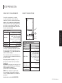
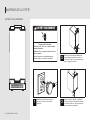
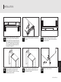
GRAVITY DRAIN SYSTEM
E
A
B
C
D
F
Gravity Drain System Dimensions
Drain Hose A
Air Gap B 1" (2.54 cm)
PVC Drain Reducer C
2" to 1
1
⁄
2
"
(5 cm - 3.8 cm)
Center of Drain D
23" (58.4 cm) from front
of door, with or without
3/4" (1.9 cm) panel on the
door, centered left to right
(7
5
⁄
16
" [18.56 cm]) from
either side of the
ice maker.
Bottom of Ice
Maker to top of
PVC Drain Reducer
E 1
7
⁄
8
" (4.8 cm)
Depth to center of
PVC Drain Reducer
F 23" (58.4 cm)

DOOR REVERSAL
10 | DOOR REVERSAL
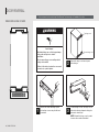
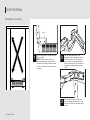
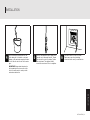
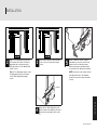
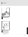
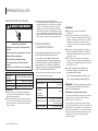
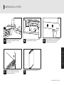
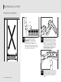
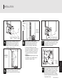
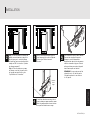
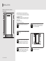
REMOVING HINGE COVERS
1
Remove the screws attaching top and
bottom hinge covers using the at head
screwdriver.
3
To remove hinge covers, cut hinge cover at
indicated point using diagonal cutting plier
and remove from hinges.
NOTE: Reinstall the hinge covers if product
is removed from cabinet installation.
2
Remove the hinge cover from top and
bottom hinges.
Top hinge cover
Bottom hinge cover
If door reversal is not needed, skip “Door Reversal” section and go to “Installation” section.!
Crush Hazard
Articulated hinges are self closing and many
pinch points exist prior to cabinet
installation.
Do not remove hinge covers until product is
ready to be installed.
Failure to follow these instructions can result
in crush, cut, or pinch injuries.
WARNING

DOOR REVERSAL
DOOR REVERSAL
DOOR REVERSAL | 11

DOOR REVERSAL
12 | DOOR REVERSAL
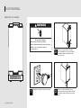
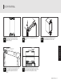
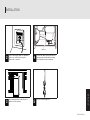
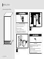
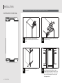
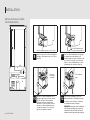
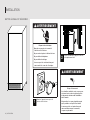
REMOVING THE HINGES
WARNING
Electrical Shock Hazard
Disconnect power before servicing.
Replace all parts and panels before operating.
Failure to do so can result in death or
electrical shock.
3
Remove screw (1) from the top and
bottom plastic end caps using the Phillips
screwdriver. Remove and place end caps
aside.
2
Remove screws (3) from the top and
bottom metal brackets using the Phillips
screwdriver. Remove and place metal
brackets aside.
1
Unplug the ice maker or disconnect power.

DOOR REVERSAL
DOOR REVERSAL
DOOR REVERSAL | 13
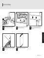
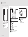
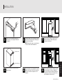
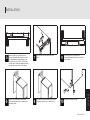
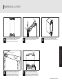
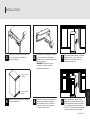
7
Remove the door and place aside.
5
Remove door swing limit pin from top hinge
and place aside.
8
Loosen the cabinet Phillips head screws
halfway, so that the top and bottom hinges
can slide off.
6
Unscrew the door hinge screws completely
from top and bottom hinges.
4
Remove the plastic screw cover from the
inside of the hinges and place aside.

DOOR REVERSAL
14 | DOOR REVERSAL
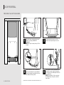
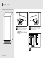
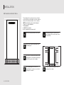
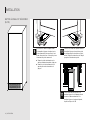
1
Once both hinges are removed, unscrew
the grill cover using a TORX T20
†
screwdriver.
NOTE: The grill cover may fall open. This is
normal.
5
4
3
2
11
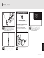
PREPARING THE BOTTOM HINGES
†TORX and T20 are trademarks of Acument Intellectual Properties, LLC.
Hinge shim
Grill cover
Black screw cover
4
Place the black screw cover between the
grill and the screws. Install the hinge shim
on the opposite side, making sure the notch
face down and in.
NOTE: Be sure that all of the cover edges
are behind the lip of the grill, or it will not
stay in place.
3
To attach the black screw cover to the
opposite side, rst pull the grill cover out.
2
Remove the black screw cover from the
grill by opening the grill cover, pushing the
screw cap inwards, and sliding it out to the
side. Remove the hinge shim.

DOOR REVERSAL
DOOR REVERSAL
DOOR REVERSAL | 15
5
Once the cover is secured, push the grill
cover back into its original position, and
reinstall the grill screws.

DOOR REVERSAL
16 | DOOR REVERSAL
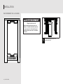
REVERSING THE HINGES
3
Take the original lower hinge, ip it and
place it in the upper hinge position on the
opposite side. Rest it on the cabinet hinge
screws.
2
Take the original upper hinge, ip it
and place it in the lower hinge position on
the opposite side. Rest it on the cabinet
hinge screws (i.e. the upper right hinge is
now the lower left hinge). The extensions on
the hinges should always face inside, not
outside.
1
Place the hinge shim on the opposite side
of the ice maker.
NOTE: The hinge shim is notched on
the bottom-inner side to indicate proper
placement. Flip the hinge shims as needed
to make sure that the notches are facing in
and down.
Notch

DOOR REVERSAL
DOOR REVERSAL
DOOR REVERSAL | 17
5
Place screw cap covers on all open screw
holes. Screw cap covers must also be
placed at the original locations of the
hinges.
7
Install the top and bottom plastic end caps
on the door (the upper right end cap is now
the lower left end cap and vice versa).
4
Both hinges should be resting on the
cabinet hinge screws. Be sure to fully
tighten all screws.
6
Reinstall the door swing limit pin on top
hinge.
8
Using screws (3), reinstall the top and
bottom metal brackets on the door.
Screw cap cover

INSTALLATION
18 | INSTALLATION
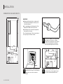
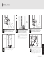
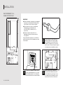
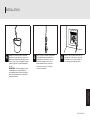
CONNECTING THE WATER SUPPLY
IMPORTANT:
■ Plumbing shall be installed in accordance with
the International Plumbing Code and any local
codes and ordinances.
■ Use copper tubing or JennAir supply line, Part
Number 8212547RP, and check for leaks.
■ Install tubing only in areas where temperatures
will remain above freezing.
Turn off main water supply. Turn on nearest faucet
line long enough to clear line of water.
1
Using a minimum 1/2" copper tubing with a
quarter turn shut-off valve or the equivalent
supply line, connect the ice maker as
shown.
2
Use 1/4" (6.35 mm) O.D. soft copper tubing
with square cut ends for the cold water
supply. Slip the compression sleeve and nut
onto the copper tubing. Be sure that you
have the proper length needed for the job.
3
Insert end of tubing squarely into outlet end
as far as it will go. Screw compression nut
onto outlet end with adjustable wrench.

INSTALLATION
INSTALLATION
INSTALLATION | 19
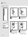
4
Flush out tubing by placing the free end
of the tubing into a container or sink, and
turning on the main water supply until water
is clear. Turn off shut-off valve on the water
pipe.
IMPORTANT: Always drain the water line
before making the nal connection to the
inlet of the water valve to avoid possible
water valve malfunction.
6
Turn shutoff valve on. Check for leaks.
Tighten any connections (including
connections at the valve) or nuts that leak.
5
Remove and discard the short, plastic tube
from the end of the water line inlet. Thread
the nut onto the end of the tubing. Tighten
the nut by hand. Then tighten it with a
wrench two more turns. Do not overtighten.

INSTALLATION
20 | INSTALLATION
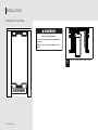
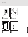
INSTALLING THE DRAIN PUMP - SITE
PREPARATION
NOTES:
■ Connect drain pump to your drain in accordance
with all state and local codes and ordinances.
■ It may be desirable to insulate drain tube
thoroughly up to drain inlet to minimize
condensation on the drain tube. Insulated tube kit
Part Number W10365792 is available for purchase.
■ Drain pump is designed to pump water to a
maximum height of 10 ft (3 m). Use only Whirlpool
approved drain pump kit Part Number 1901A.
■ Do not connect the outlet end of the drain tube
to a closed pipe system to keep drain water from
backing up into the ice maker.
Kit Contains:
■ Drain pump kit Part Number 1901A
■ 5/8" I.D. x 51/8" drain tube (ice maker bin to drain
pump reservoir inlet)
■ 1/2" I.D. x 10 ft (3 m) drain tube hose (drain pump
discharge to household drain)
■ 5/16" I.D. x 32" (81 cm) vent tube (drain pump
reservoir vent to ice maker cabinet back)
■ Cable tie (secures vent tube to black suction tube)
(1)
■ #8-32 x 3/8" pump mounting screws (secures
drain pump to baseplate and clamps to back of ice
maker) (5)
■ 5/8" small adjustable hose clamp (secures vent to
drain pump)
■ 7/8" large adjustable hose clamp, (secures drain
tube to ice maker bin and drain pump reservoir
inlet) (3)
■ Instruction sheet
If Ice Maker is Currently Installed
NOTE: If ice maker is not installed, please proceed to
“Drain Pump Installation” section.
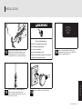
1
Press the OFF button to Stop ice
production. Then unplug the ice maker or
disconnect power.
3
If ice maker is built into cabinets, pull ice
maker out of the opening.
If drain pump is not needed, skip “Drain Pump Installation” section and go to “Connecting the Drain” section.!
WARNING
Electrical Shock Hazard
Disconnect power before servicing.
Replace all parts and panels before
operating.
Failure to do so can result in death or
electrical shock.
La page est en cours de chargement...
La page est en cours de chargement...
La page est en cours de chargement...
La page est en cours de chargement...
La page est en cours de chargement...
La page est en cours de chargement...
La page est en cours de chargement...
La page est en cours de chargement...
La page est en cours de chargement...
La page est en cours de chargement...
La page est en cours de chargement...
La page est en cours de chargement...
La page est en cours de chargement...
La page est en cours de chargement...
La page est en cours de chargement...
La page est en cours de chargement...
La page est en cours de chargement...
La page est en cours de chargement...
La page est en cours de chargement...
La page est en cours de chargement...
La page est en cours de chargement...
La page est en cours de chargement...
La page est en cours de chargement...
La page est en cours de chargement...
La page est en cours de chargement...
La page est en cours de chargement...
La page est en cours de chargement...
La page est en cours de chargement...
La page est en cours de chargement...
La page est en cours de chargement...
La page est en cours de chargement...
La page est en cours de chargement...
La page est en cours de chargement...
La page est en cours de chargement...
La page est en cours de chargement...
La page est en cours de chargement...
La page est en cours de chargement...
La page est en cours de chargement...
La page est en cours de chargement...
La page est en cours de chargement...
La page est en cours de chargement...
La page est en cours de chargement...
La page est en cours de chargement...
La page est en cours de chargement...
La page est en cours de chargement...
La page est en cours de chargement...
La page est en cours de chargement...
La page est en cours de chargement...
La page est en cours de chargement...
La page est en cours de chargement...
La page est en cours de chargement...
La page est en cours de chargement...
La page est en cours de chargement...
La page est en cours de chargement...
-
 1
1
-
 2
2
-
 3
3
-
 4
4
-
 5
5
-
 6
6
-
 7
7
-
 8
8
-
 9
9
-
 10
10
-
 11
11
-
 12
12
-
 13
13
-
 14
14
-
 15
15
-
 16
16
-
 17
17
-
 18
18
-
 19
19
-
 20
20
-
 21
21
-
 22
22
-
 23
23
-
 24
24
-
 25
25
-
 26
26
-
 27
27
-
 28
28
-
 29
29
-
 30
30
-
 31
31
-
 32
32
-
 33
33
-
 34
34
-
 35
35
-
 36
36
-
 37
37
-
 38
38
-
 39
39
-
 40
40
-
 41
41
-
 42
42
-
 43
43
-
 44
44
-
 45
45
-
 46
46
-
 47
47
-
 48
48
-
 49
49
-
 50
50
-
 51
51
-
 52
52
-
 53
53
-
 54
54
-
 55
55
-
 56
56
-
 57
57
-
 58
58
-
 59
59
-
 60
60
-
 61
61
-
 62
62
-
 63
63
-
 64
64
-
 65
65
-
 66
66
-
 67
67
-
 68
68
-
 69
69
-
 70
70
-
 71
71
-
 72
72
-
 73
73
-
 74
74


Jenn-Air JUIFN15HX Guide d'installation
- Taper
- Guide d'installation
- Ce manuel convient également à
dans d''autres langues
Documents connexes
Autres documents
-
Maytag W10520283B User Instructions
-
KitchenAid WUI75X15HZ Guide d'installation
-
KitchenAid KUIO338HSS Guide d'installation
-
Maytag W10520283B Le manuel du propriétaire
-
KitchenAid WUI75X15HB Guide d'installation
-
KitchenAid KUIX335HPS Guide d'installation
-
JennAir JUIFN15HX Mode d'emploi
-
KitchenAid P6WG2KL Mode d'emploi
-
-