
B347808886COM04GO
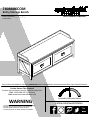
- Unit can tip over causing severe injury or death.
- Anchor unit to stud in wall (if instructed to).
- Do Not allow children to climb on unit.
- Put heavy items on lower shelves or drawers.
WARNING
THIS INSTRUCTION BOOKLET CONTAINS IMPORTANT SAFETY INFORMATION. PLEASE READ AND KEEP FOR FUTURE REFERENCE.
Do Not Return This Product!
Contact our customer service team for help first.
Call: 1-800-489-3351 (toll free)
Visit: www.ameriwoodhome.com
Follow Ameriwood Home
Date of Purchase ___ / ___ / ___
Lot Number:
7808886COM
Entry Storage Bench
Tube
You
Assembly Difficulty Meter
Easy Tough

Do NOT return this product!
Contact our friendly customer service team first for help.
Call us!
1-800-489-3351
Visit ameriwoodhome.com
Assembly Tips
- Open your item in the area you plan to keep it to avoid excessive heavy lifting.
- Identify, sort and count the parts before attempting assembly.
- Compression dowels are lightly tapped in with a hammer.
- Slides are labeled with a R (right) and L (left) for proper placement.
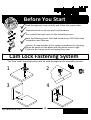
- Make sure to always face the point on the top of the Cam Lock towards the
outer edge.
- Use all the nails provided for the back panel and spread them out equally.
- Back panel must be used to make sure your unit is sturdy.
- Do NOT use harsh chemicals or abrasive cleaners on this item.
- Never push, pull, or drag your furniture.
Tube
You
PEOPLE NEEDED FOR ASSEMBLY: 1-2
ESTIMATED ASSEMBLY TIME: 1 HOUR
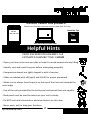
Helpful Hints
2
Tube
You
systembuild.com

P
Quick
Tip
Assembly
P
P
P
Read through each step carefully and follow the proper order
Separate and count all your parts and hardware
Give yourself enough room for the assembly process
Have the following tools: Flat Head Screwdriver, #2 Phillips Head
Screwdriver and Hammer
Caution: If using a power drill or power screwdriver for screwing,
please be aware to slow down and stop when screw is tight.
Failure to do so may result in stripping the screw.
P
Before You Start
Cam Lock Fastening System
This Cam Lock Fastening System will be used throughout the assembly process.
1
3
2
4
3
Tube
You
systembuild.com

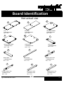
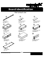
Board Identification
Not actual size
TOP
T7808886010GO
QTY: 1 PC
A
4
Tube
You
systembuild.com
BOTTOM
T7808886020GO
QTY: 1 PC
B
LEFT SIDE PANEL
T7808886031GO
QTY: 1 PC
C
RIGHT SIDE PANEL
T7808886041GO
QTY: 1 PC
D
PARTITION
T7808886051GO
QTY: 1 PC
E
LEFT RAIL
T7808886060GO
QTY: 1 PC
F
RIGHT RAIL
T7808886070GO
QTY: 1 PC
G
BACK RAIL
T7808886080GO
QTY: 1 PC
H
FRONT LEFT LEG
T7808886091GO
QTY: 1 PC
I
FRONT RIGHT LEG
T7808886101GO
QTY: 1 PC
J
REAR LEFT LEG
T7808886110GO
QTY: 1 PC
K
REAR RIGHT LEG
T7808886120GO
QTY: 1 PC
L

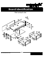
Board Identification
Not actual size
5
Tube
You
systembuild.com
TOP APRON
T7808886130GO
QTY: 1 PC
M
BOTTOM SUPPORT
T7808886140GO
QTY: 1 PC
N
BOTTOM SUPPORT
T7808886150GO
QTY: 1 PC
O
DRAWER FRONT
T7808886161GO
QTY: 2 PCS
P
LEFT DRAWER SIDE
T7808886172GO
QTY: 2 PCS
Q
RIGHT DRAWER SIDE
T7808886182GO
QTY: 2 PCS
R
DRAWER BACK
T7808886191GO
QTY: 2 PCS
S
DRAWER BOTTOM
T7808886201GO
QTY: 2 PCS
T
DRAWER SUPPORT
T7808886210GO
QTY: 2 PCS
U
BACK PANEL
T7808886220GO
QTY: 1 PC
V

Board Identification
Not actual size
6
Tube
You
systembuild.com
A
B
C
D
E
F
G
H
I
J
K
L
M
N
O
P
P
Q
Q
R
R
S
S
T
T
U
U
V

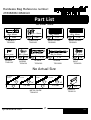
Part List
Hardware Bag Reference number:
27808886COM2GO
Actual Size
×26
Ø15 x 10mm
CAM LOCK
TGO2100
2
×26
CAM BOLT
TGO2000
Ø8 x 20mm
7
Tube
You
1
systembuild.com
×18
SCREW
TGO1301
Ø3 x 12mm
6 ×4
M4 x 12mm
×15
Ø4.2 x 45mm
SCREW
TGO1008
BOLT
TGO1620
98
×18
WOOD DOWEL
TGO2903
Ø6 x 30mm
4
×17
WOOD DOWEL
TGO2900
Ø8 x 30mm
3
×28
SCREW
TGO1007
Ø3.5 x 12mm
5 ×12
Ø4.2 x 32mm
SCREW
TGO1022
7
No Actual Size
×2 set
14"
left cabinet
member
left drawer
member
×2 set
right cabinet
member
right drawer
member
11
10
10-1 10-2 11-1 11-2 14"
×2
HANDLE
TGO5513
12
METAL SLIDE
TGO4513

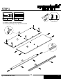
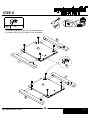
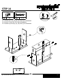
STEP 1
1.1 Screw (1) into (A) as illustrated.
1.2 Insert (3) into (B), (H) & (M) as illustrated.
×6
8
Tube
You
1
systembuild.com
×10
3
1
A
B
H
M
3

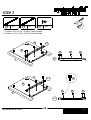
STEP 2
9
Tube
You
4
2.1 Insert (4) into (C) & (D) as illustrated.
systembuild.com
×12
C
D
4

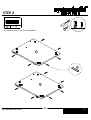
STEP 3
10
Tube
You
×14
1
3.1 Screw (1) into (F), (G), (I), (J), (K) & (L) as illustrated.
3.2 Insert (3) into (F) & (G) as illustrated.
systembuild.com
3 ×2 Proper orientation of CAM LOCK
Tip
Quick
Assembly
UNLOCK
LOCK
3
FG
I
J
KL
1

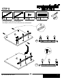
4.1 Attach (F) & (G) to (H) with (2) as illustrated.
4.2 Connect (F), (G), (H) & (A) together by (3) as illustrated.
STEP 4
11
Tube
You
systembuild.com
Proper orientation of CAM LOCK
Tip
Quick
Assembly
UNLOCK
LOCK
×2
2
H
G
F
H
A
G
F
2

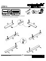
STEP 5
12
Tube
You
Proper orientation of CAM LOCK
Tip
Quick
Assembly
UNLOCK
LOCK
systembuild.com
5.1 Attach (F), (G), (H) & (M) to (A) with (8) as illustrated.
×108
G
H
F
A
M
8

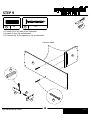
6.1 Attach (I) & (K) to (C) with (2) as illustrated.
6.2 Attach (J) & (L) to (D) with (2) as illustrated.
STEP 6
13
Tube
You
systembuild.com
C
I
K
J
L
D
2
Proper orientation of CAM LOCK
Tip
Quick
Assembly
UNLOCK
LOCK
×8
2

STEP 7
14
Tube
You
7.1 Attach (10-2) to (C) , (I) with (5) as illustrated.
7.2 Attach (11-2) to (D), (J) with (5) as illustrated.
systembuild.com
10-2 ×1 11-2 ×1 ×85
5 5 5
5
5
5
10-2
C
I
K
11-2
11-2
10-2
5
D
J
L

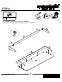
STEP 8
15
Tube
You
systembuild.com
8.1 Insert (3) into (E) as illustrated.
8.2 Attach (10-2) & (11-2) to (E) with (5) as illustrated.
10-2 ×1 11-2 ×1 ×85 3 ×3
555
10-2
5
5
5
11-2
5
E
E
3

STEP 9
16
Tube
You
systembuild.com
9.1 Attach (E) to (B) with (8) as illustrated.
9.2 Insert (3) into (O) as illustrated.
9.3 Connect (N) & (O) together by (3) as illustrated.
3 ×2 ×28
N
O3
3
8
FINISHED EDGE
E
B

STEP 10
17
Tube
You
systembuild.com
10.1 Attach (C) & (D) to (B) with (2) as illustrated.
10.2 Attach (N) & (O) to (B) with (8) as illustrated.
2 ×4 ×38 Proper orientation of CAM LOCK
Tip
Quick
Assembly
UNLOCK
LOCK
B
D
C
N
O
82

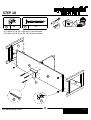
STEP 11
18
Tube
You
systembuild.com
11.1 Attach (A) to (C), (D) & (E) with (2) as illustrated.
2 ×6 Proper orientation of CAM LOCK
Tip
Quick
Assembly
UNLOCK
LOCK
D
C
E
A
2

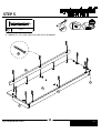
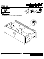
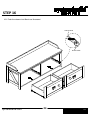
STEP 12
19
Tube
You
systembuild.com
×186
12.1 Attach (V) to sub-assembly A/B/C/D from previous step with (6) as illustrated.
* Assure that the unit is square. Distance from corner to corner must be equal as
shown.
IMPORTANT! THE BACK PANEL IS A STRUCTURAL PART
OF THIS UNIT AND MUST BE INSTALLED PROPERLY.
D
C
V
B
A
6

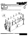
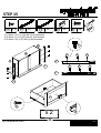
STEP 13
20
Tube
You
systembuild.com
×6
1 4 ×6
13.1 Insert (4) into (R), (Q), (U) as illustrated.
13.2 Cam bolt (1) into (1) as illustrated.
R
Q
P
U
x 2
4
1
4
4
La page est en cours de chargement...
La page est en cours de chargement...
La page est en cours de chargement...
La page est en cours de chargement...
La page est en cours de chargement...
La page est en cours de chargement...
La page est en cours de chargement...
La page est en cours de chargement...
La page est en cours de chargement...
La page est en cours de chargement...
La page est en cours de chargement...
-
 1
1
-
 2
2
-
 3
3
-
 4
4
-
 5
5
-
 6
6
-
 7
7
-
 8
8
-
 9
9
-
 10
10
-
 11
11
-
 12
12
-
 13
13
-
 14
14
-
 15
15
-
 16
16
-
 17
17
-
 18
18
-
 19
19
-
 20
20
-
 21
21
-
 22
22
-
 23
23
-
 24
24
-
 25
25
-
 26
26
-
 27
27
-
 28
28
-
 29
29
-
 30
30
-
 31
31


dans d''autres langues
- español: Dorel Home 7808886COM
Documents connexes


Autres documents
-
Ameriwood HD34376 Mode d'emploi
-
-
ROOMS TO GO 21511539 Assembly Instructions
-
-
Ameriwood Home HD45101 Mode d'emploi
-
-
-
-