
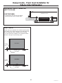
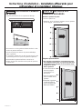
INSTALLATION
INSTRUCTIONS
with Design Guide
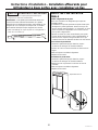
Flush Inset Installation for Built-In Refrigerators
Pour obtenir une version française de ce manuel d’instructions,
visitez notre site monogram.com.
Para consultar una version en español de este manual de instrucciones,
visite nuestro sitio de internet monogram.com.
MONOGRAM.COM

2
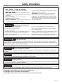
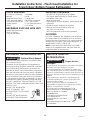
Safety Information
BEFORE YOU BEGIN
Read these instructions completely and carefully.
•
IMPORTANT – Save these instructions for
local inspector’s use. Observe all governing codes and
ordinances.
•
Note to Installer – Be sure to leave these
instructions with the Consumer.
• Note to Consumer – Keep these instructions with
your Owner’s Manual for future reference.
If you received a damaged unit, you should immediately
contact your dealer or builder.
Skill Level – Installation of this unit requires basic
mechanical, carpentry and plumbing skills. Proper
installation is the responsibility of the installer. Product
failure due to improper installation is not covered under
the Monogram Warranty. See the Owner’s Manual for
warranty information.
For Monogram local service in your area, visit monogram.com
For Monogram service in Canada, visit monogram.ca
For Monogram Parts and Accessories, visit monogram.com/use-and-care/parts
WARNING
Tip Over Hazard.
These appliances are top heavy, especially with any doors open, and must be secured to prevent tipping
forward which could result in death or serious injury. Read and follow the entire installation instructions for
securing the appliance with the anti-tip system.
WARNING
Fire or Explosion Hazard.
Keep flammable materials and vapors away from appliance. Failure to do so can result in fire, explosion,
or death.
WARNING
To reduce the risk associated with choking, do not allow children under 3 years of age to
have access to small parts during the installation of this product.
CAUTION
Lifting Hazard
This unit is very heavy. To reduce the risk of person injury during maneuvering and installing this appliance,
3 people are required for proper installation.
CAUTION
Keep fingers out of the “pinch point” areas; clearances between the doors and between the
doors and cabinet are necessarily small. Be careful closing doors when children are in the area.
WARNING
Electrical Shock Hazard.
Plug into a grounded 3-prong outlet.
Do not remove the ground prong.
Do not use an adapter.
Immediately discontinue use of a damaged supply cord.
If the supply cord is damaged it must be replaced by a
qualified service professional with an authorized service
part from the manufacturer.
Do not use an extension cord with this appliance.
Failure to follow these instructions can result in death,
fire, or electrical shock.
Follow the instructions in the section Grounding the unit.
This appliance must be installed with a means in the
fixed house wiring or circuit breaker for disconnecting the
appliance from the electrical supply after installation.
31-1000454 Rev. 2

3
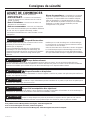
Consignes de sécurité
AVANT DE COMMENCER
Veuillez lire toutes ces instructions attentivement.
• IMPORTANT – Conservez ces instructions à
l’usage de l’inspecteur local. Observez tous les codes et
décrets en vigueur.
•
Note à l’installateur – Assurez-vous de laisser ces
instructions au consommateur.
•
Note au consommateur - Conservez ces instructions
avec votre manuel d’utilisation pour
consultation ultérieure.
Si vous avez reçu un appareil endommagé, veuillez
communiquer immédiatement avec votre revendeur ou votre
entrepreneur.
Niveau de compétence – L’installation de cet appareil
exige des compétences de base en mécanique, menuiserie
et plomberie. La responsabilité d’une installation adéquate
relève de l’installateur. La garantie Monogram ne couvre
pas les défectuosités du produit causées par une installation
inadéquate. Consultez le manuel d’utilisation pour des
renseignements sur la garantie.
AVERTISSEMENT
Risque de basculement.
Ces électroménagers sont lourds du haut, notamment lorsqu’une porte est ouverte, de sorte qu’ils doivent être fixés pour
prévenir un basculement vers l’avant susceptible d’occasionner des blessures graves ou la mort. Lisez et observez la totalité des
instructions d’installation pour connaître la façon de fixer l’électroménager sur le dispositif antibasculement.
AVERTISSEMENT
Risque d'incendie ou d'explosion.
Gardez les matériaux et les vapeurs inflammables à l’écart de l’appareil. L’omission de prendre cette précaution peut entraîner un
incendie, une explosion ou la mort.
AVERTISSEMENT
Pour réduire le risque d’étouffement pendant l’installation de ce produit, ne pas laisser les petites pièces
à la portée des enfants âgés de moins de 3 ans.
AVERTISSEMENT
Risque lié à la manipulation d’un objet lourd
Cet appareil est très lourd. Afin de réduire le risque de blessure pendant la manipulation et l’installation de cet électroménager, la
participation de 3 personnes est nécessaire à l’exécution d’une installation correcte.
AVERTISSEMENT
Gardez vos doigts éloignés des points de pincement. Les espaces entre les portes et ceux entre les
portes et l’armoire sont particulièrement restreints. Soyez prudent lorsque vous fermez les portes en présence d’enfants.
AVERTISSEMENT
Risque d’électrocution.
Branchez l’appareil dans une prise à 3 broches mise à la terre.
N’enlevez pas la broche de mise à la terre.
N’utilisez pas un adaptateur.
Cessez immédiatement l’utilisation d’un cordon électrique
endommagé. Si le cordon électrique est endommagé, son
remplacement doit être exécuté par un technicien en réparation
qualifié au moyen d’un cordon de rechange autorisé par le
fabricant.
N’utilisez pas un cordon de rallonge avec cet électroménager.
Le non-respect de ces instructions peut occasionner un décès,
un incendie ou un choc électrique
Suivez les instructions de la section Mise à la terre de l’appareil.
Le circuit électrique auquel cet électroménager sera raccordé
doit comporter un disjoncteur ou un autre dispositif permettant
de couper l’alimentation électrique à l’appareil après l’installation.
Pour joindre le service Monogram de votre région, visitez monogram.com
Pour le service Monogram au Canada, visitez monogram.ca
Pour le service des Pièces et accessoires Monogram, visitez monogram.com/use-and-care/parts.
31-1000454 Rev. 2

4
Información sobre Seguridad
ANTES DE COMENZAR
Lea estas instrucciones en su totalidad y atentamente.
•
IMPORTANTE – Conserve estas
instrucciones para uso del inspector local. Cumpla con
todos los códigos y ordenanzas gubernamentales.
•
Nota para el Instalador – Asegúrese de entregarle
estas instrucciones al Comprador.
• Nota para el Consumidor – Guarde estas
instrucciones con su Manual del Propietario para
referencia futura.
Si la unidad que recibió está dañada, se deberá
comunicar de inmediato con su vendedor o fabricante.
Nivel de habilidad – La instalación de esta unidad
requiere un nivel básico de habilidades mecánicas,
de carpintería y plomería. La correcta instalación
del producto es responsabilidad del instalador. Si se
producen fallas en el producto debido a una instalación
inadecuada, la Garantía de Monogram no cubrirá las
mismas. Para obtener información sobre la garantía,
consulte el Manual del Propietario.
ADVERTENCIA
Riesgo de Caídas
Estos electrodomésticos son inestables, especialmente cuando una puerta se encuentre abierta, y deben estar
asegurados a fin de evitar caídas hacia adelante que podrían resultar en la muerte o en lesiones graves. Lea y siga
las instrucciones de instalación en su totalidad para asegurar el electrodoméstico con el sistema anti volcaduras.
ADVERTENCIA
Peligro de Incendio o Explosión
Mantenga cualquier material y vapores inflamables alejados del electrodoméstico. Si no se cumple con esto, se podrá
producir una explosión, un incendio o la muerte.
ADVERTENCIA
A fin de reducir el riesgo asociado con descargas, no permita que los niños menores de 3
años de edad tengan acceso a las partes pequeñas durante la instalación de este producto.
PRECAUCIÓN
Riesgo al levantar la puerta
Este refrigerador es muy pesado. A fin de reducir el riesgo de lesiones personales durante la maniobra e instalación
de este refrigerador, se requiere contar con 3 personas para una correcta instalación del modelo de 36” de ancho y
con 4 personas para una correcta instalación del modelo de 42” o 48”.
PRECAUCIÓN
Mantenga los dedos fuera de los espacios de “riesgo de lastimaduras”; los espacios entre
las puertas y entre las puertas y el gabinete son necesariamente pequeños. Tenga el cuidado de cerrar las puertas
cuando se encuentren niños en el área.
ADVERTENCIA
Riesgo de Descarga Eléctrica
Enchufe en un tomacorriente con conexión a tierra de 3
cables.
No elimine el cable de conexión a tierra.
No use un adaptador.
Inmediatamente interrumpa el uso de un cable de
suministro de corriente dañado. Si el cable de corriente se
encuentra dañado, su reemplazo deberá ser realizado por
un profesional calificado del servicio técnico, utilizando una
pieza del servicio técnico autorizada por el fabricante.
No use prolongadores con este electrodoméstico.
Si no se siguen estas instrucciones, se podrá producir la
muerte, incendios o descargas eléctricas.
Siga las instrucciones que figuran en la sección de
Conexión de Tierra de la unidad.
Este electrodoméstico deberá ser instalado por algún
medio en el cableado fijo del hogar o en un disyuntor para
desconectar el electrodoméstico del suministro eléctrico
luego de la instalación.
Para acceder al servicio local de Monogram en su área, visite monogram.com
Para acceder al servicio de Monogram en Canadá, visite monogram.ca
Para acceder a Piezas y Accesorios de Monogram, visite monogram.com/use-and-care/parts
31-1000454 Rev. 2

5
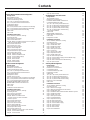
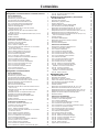
Contents
Safety 2
French Door Bottom Freezer Refrigerator 6
Design Guide
The Installation Space 7
Dimensions and Clearances 7
Custom Handle Design Guide 7
1/2” (1.27 cm) Overlay Panel Dimensions 8
3/4” (1.9 cm) Decorative Panel Dimensions 9
Customization Basics 9
Refrigerator Location 9
3/4” (1.9 cm) Raised Fresh Food Door Panel Routing 10
3/4” (1.9 cm) Raised Freezer Drawer Panel Routing 11
3/4” (1.9 cm) Raised Grille Panel Routing 12
Side Panels 13
Side Cleats 13
Installation Instructions
Tools, Hardware, Materials, Flooring 14
Grounding the Unit 14
Step 1. Remove Packaging 15
Step 2. Install Water Line 15
Step 2A. Water Line with Reverse Osmosis System or
other Household Filtration System 15
Step 3. Install Side Panels 16
Step 4. Install Case Trim 16
Step 5. Anti-Tip Procedures 16
Step 6. Level Refrigerator 18
Step 7, Secure Unit to Wall 18
Step 8. Alternate Anti-Tip Procedure 19
Step 9. Adjust Door Swing 19
Step 10. Install Grille Panel 20
Step 11. Install Assembled Panels 20
Step 12. Connect Water Supply 21
Step 13. Connect Power 21
Step 14. Start Icemaker 21
Step 15. Install Toekick 22
Inspect Final Installation 22
Bottom Freezer Refrigerator 23
Design Guide
The Installation Space 24
Dimensions and Clearances 24
Custom Handle Design Guide 24
1/2” (1.27 cm) Overlay Panel Dimensions 25
3/4” (1.9 cm) Decorative Panel Dimensions 26
Customization Basics 26
Refrigerator Location 26
Optional Accessory Kits 26
3/4” (1.9 cm) Raised Fresh Food Door Panel Routing 27
3/4” (1.9 cm) Raised Freezer Drawer Panel Routing 28
3/4” (1.9 cm) Raised Grille Panel Routing 29
Installation ZKBFN720NII Unification Kit 30
ZKBFN720NII Unification Kit Dimensions 30
Side Panels 30
Side Cleats 30
Unified Door Panel Dimensions 30
Installation Instructions
Tools, Hardware, Materials, Flooring 31
Grounding the Unit 31
Step 1. Remove Packaging 32
Step 2. Install Water Line 32
Step 2A. Water Line with Reverse
Osmosis System or other Household
Filtration System 33
Step 3. Install Side Panels 33
Step 4. Install Case Trim 33
Step 5. Anti-Tip Procedures 33
Step 6. Level Refrigerator 36
Step 7. Alternate Anti-Tip Procedure 36
Step 8. Adjust Door Swing 37
Step 9. Install Grille Panel 37
Step 10. Install Door Panels and Custom Handles 38
Step 11. Connect Water Supply 38
Step 12. Connect Power 39
Step 13. Start Icemaker 39
Step 14. Install Toekick 39
All-Refrigerator and All-Freezer 40
Design Guide
The Installation Space 41
Dimensions and Clearances 41
Installation ZKBFN720NII Unification Kit 42
Custom Handle Design Guide 42
1/2” (1.27 cm) Overlay Panel Dimensions 43
3/4” (1.9 cm) Decorative Panel Dimensions 44
3/4” (1.9 cm) Raised Door Panel Routing 45
3/4” (1.9 cm) Raised Grille Panel Routing 46
3/4” (1.9 cm) Raised Door Panel Routing
for Unified Installation 47
Side Panels 48
ZKBFN720NII Unification Kit 48
Unified Door Panel Dimensions 48
Side Cleats 49
Refrigerator Location 49
Installation Instructions
Tools, Hardware, Materials, Flooring 50
Grounding the Unit 50
Step 1. Remove Packaging 51
Step 2. Install Water Line 51
Step 3. Install Side Panels 51
Step 4. Install Case Trim 52
Step 5. Anti-Tip Procedures 52
Step 6. Level Unit 54
Step 7 Secure Unit to Wall 55
Step 8. Adjust Door Swing 55
Step 9. Install Grille Panel 55
Step 10. Install Overlay Panels 56
Step 11. Connect Water Supply (Freezer Models Only) 57
Step 12. Connect Power 57
Step 13. Start Icemaker(Freezer Models Only) 57
Step 14. Install Toekick 58
Side-by-Side Refrigerator 59
Design Guide
The Installation Space 60
Dimensions and Clearances 60
Customization Basics 61
Custom Handle Design Guide 61
Refrigerator Location 61
Side Panels 61
1/2” (1.27 cm) Overlay Panel Dimensions 62
3/4” (1.9 cm) Raised Panel Dimensions 63
3/4” (1.9 cm) Raised Door Panel Routing 64
3/4” (1.9 cm) Raised Grille Panel Routing 65
Dispenser Trim Fit Examples 66
Side Cleats 66
Installation Instructions
Tools, Hardware, Materials, Flooring 67
Grounding the Unit 67
Step 1. Remove Packaging 68
Step 2. Move the Refrigerator into the House 68
Step 3. Install Water Line 68
Step 4. Installation with Household Water Filtration System 69
Step 5. Install Side Panels 69
Step 6. Install Case Trim 69
Step 7. Anti-Tip Procedures 70
Step 8. Level Refrigerator 70
Step 9. Adjust Door Swing 71
Step 10. Install Grille Panel 71
Step 11. Install Overlay Panels 72
Step 12. Connect Water Supply 73
Step 13. Connect Power 74
Step 14. Start Icemaker 74
Step 15. Install Toekick 75
Inspect Final Installation 75
31-1000454 Rev. 2

6
Instructions for French Door
Bottom Freezer Refrigerator
31-1000454 Rev. 2

7
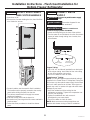
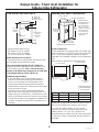
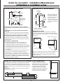
Design Guide - Flush Inset Installation for French Door
Bottom Freezer Refrigerator
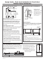
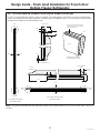
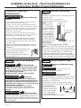
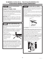
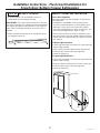
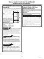
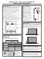
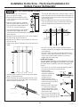
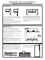
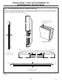
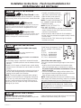
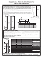
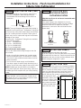
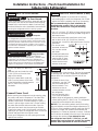
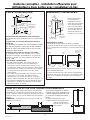
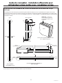
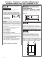
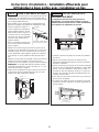
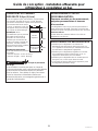
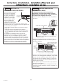
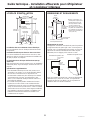
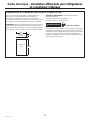
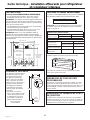
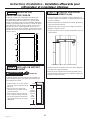
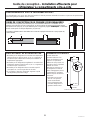
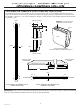
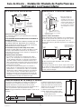
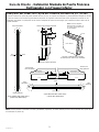
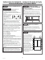
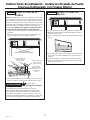
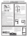
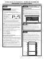
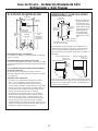
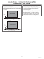
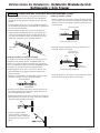
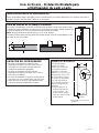
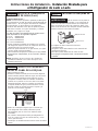
CUSTOM HANDLE DESIGN GUIDE
Custom handles must be used for Flush Inset Installation.
For custom handle installation, counterbore holes in rear
of decorative panels must ensure 1/2” (1.27 cm) material
thickness remains for handle support.
NOTE: The counterbore must not exceed 1” (2.54 cm) in
diameter.
Minimum distance on Fresh Food
Doors from handle side edge to handle
center should be 1-1/4" (3.18 cm) on
each door as shown.
Minimum distance on Freezer Door
from top edge to handle center on the
freezer drawer should be 1-1/2”
(3.81 cm) as shown.
1/4”
1/2”
3/4”
7/8"
0.85"
1/2"
1-1/4”
1-1/4”
1-1/2”
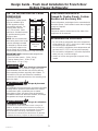
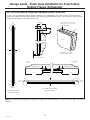
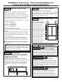
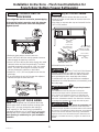
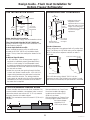
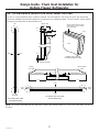
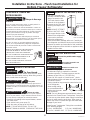
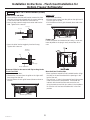
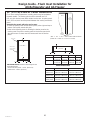
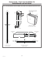
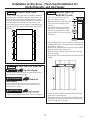
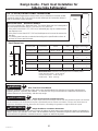
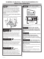
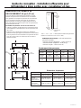
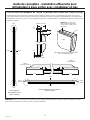
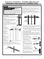
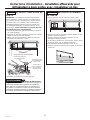
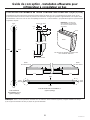
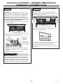
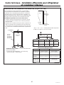
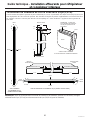
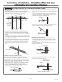
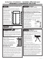
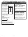
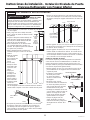
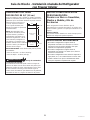
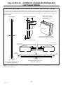
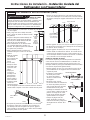
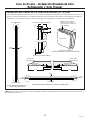
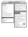
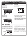
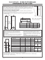
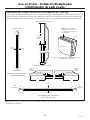
THE INSTALLATION SPACE
Water And Electrical Locations
Electrical and water supply must be located as shown.
The cutout depth must be 26-3/16” (66.52 cm)
The refrigerator will project forward, slightly beyond
adjacent cabinetry, depending on your installation.
Allow minimum 1/8” (0.32 cm) air gap between case
back & wall.
Cutout depth beneath a soffit:
When installed beneath a soffit, the soffit cannot exceed
the 24” (60.96 cm) installation depth shown. The top
case trim overlaps the bottom of the soffit.
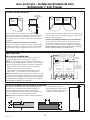
Additional Specifications
• A 115 volt 60Hz., 15 or 20 amp power supply is
required. An individual properly grounded branch
circuit or circuit breaker is recommended. Install
a properly grounded 3-prong electrical receptacle
recessed into the back wall. Electrical must be located
on rear wall as shown.
• Water line can enter the opening through the floor
or back wall. Route SmartConnect
™
kit or 1/4” O.D.
copper tubing between the cold water line and the
water connection location. The tubing should be
long enough to extend to the front of the refrigerator.
Installation of an easily accessible shut-off valve in the
water line is required.
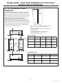
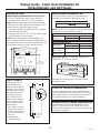
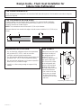
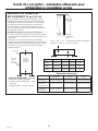
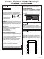
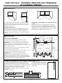
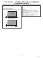
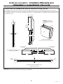
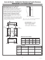
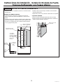
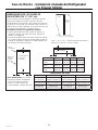
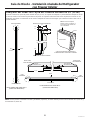
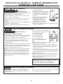
DIMENSIONS AND CLEARANCES
Product Clearances
These refrigerators are equipped with a 3-position door
stop. The factory set 115° door swing can be adjusted
to 90° if clearance to adjacent cabinets or walls is
restricted.
Do not use the 130° door swing option for flush
installation.
For a 90° door swing, allow 4” (10.16 cm) min.
clearance to adjacent wall from cutout. If the 90° door
stop position is used, pan access is maintained, but pan
removal is restricted.
23-7/8"
Behind
Frame
90°90°
19-1/2”
4” Min. Distance
to Adjacent Wall
from Cutout
8"
Min. to
Wall
8"
Min. to
Wall
115°
115°
6"
Wall View
Electrical
Area
85"
Finished
Opening
75-1/2" From
Floor to
Bottom
of Electrical Area
10"
26-3/16" Cutout
Depth
39"
Finished Width
4-1/16"
7"
3-1/2"
3-1/2"
3-1/2" 3-1/2"
7"
3-1/2"
Water Supply
* Shipping height. The
refrigerator can be
adjusted to fit into a cutout
that is 85
” (215.9 cm)
max. height. Use leveling
legs and wheels for a
maximum 1
” (2.54 cm)
height adjustment.
36" Frame to
Frame Width
*84" From
Floor to
Top Frame
35"
Case Width
*83 1/2"
at
Rear
Depth Including
Handles: 27-1/2"
31-1000454 Rev. 2

8
Design Guide - Flush Inset Installation for French Door
Bottom Freezer Refrigerator
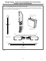
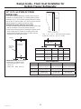
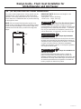
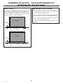
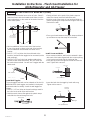
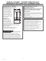
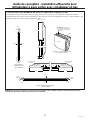
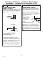
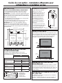
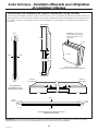
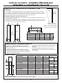
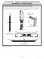
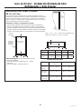
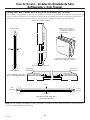
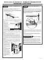
1/2” (1.27 cm) OVERLAY PANEL
DIMENSIONS
For a more custom appearance, overlay panels may be
installed on trimmed models. The overlay panel must
be secured to a 1/4” (.64 cm) thick backer panel which
slides into the trim. A spacer panel 0.10” (0.25 cm) thick
must be placed between the overlay and backer panel.
Assemble the panels with glue and screws:
• Center the spacer panel on the backer panel, left to
right and top to bottom. Secure the panels with glue.
• Refer to the following chart for locating the backer panel
to the overlay panel. Secure the overlay panel to the
backer panel with glue and screws. Screws must be
countersunk into the backer panel.
Fresh Food Freezer Grille
1/4” (0.63 cm)
Backer Panel
46-1/16” x 16-1/2”
(116.99 cm x 41.91 cm)
21-7/8” x 33-7/8”
(55.56 cm x 86.04 cm)
8-7/8” x 33-7/8”
(22.54 cm x 86.04 cm)
.10” (0.25 cm)
Spacer Panel
44-11/16” x 15”
(113.51 cm x 38.10 cm)
20-1/2” x 32-1/2”
(52.07 cm x 82.55 cm)
7-5/8” x 32-1/2”
(19.37 cm x 82.55 cm)
1/2” (1.27 cm)
Overlay Panel
46-7/16” x 18-3/4”
(120.49 cm x 47.63 cm)
22-3/8” x 38"
(56.83 cm x 96.52 cm)
10-13/16” x 38”
(27.46 cm x 96.52 cm)
.250” + .10” + .50” = .850” Total Panel Thickness
(0.635 cm + 0.254 cm + 1.27 cm = 2.159)
1/2"
Overlay
Panel
1/4"
Backer
Panel
Door
.10"
Spacer
ABCD
Door Panels 2-1/16”
(5.24 cm)
3/16”
(0.47 cm)
3/16”
(0.47 cm)
3/16”
(0.47 cm)
Drawer Panel 2-1/16”
(5.24 cm)
2-1/16”
(5.24 cm)
1/4”
(0.64 cm)
1/4”
(0.63 cm)
Grille Panel 2-1/16”
(5.24 cm)
2-1/16”
(5.24 cm)
1-11/16”
(4.28 cm)
1/4”
(0.63 cm)
Panel Dimensions
Hinge
Side
Hinge
Side
Handle
Side
Fresh
Food
Back
Backer with
Overlay Panel
Assembly
A
B
C
D
Fresh
Food
Back
A
B
C
D
C
D
A B
Grille Back
C
D
A B
Freezer Back
Panel Locations
IMPORTANT NOTE: Maximum total weight for the
assembled panels:
• Fresh food door panels – 30 lbs. (14 kg)
• Freezer drawer panel – 28 lbs.(13 kg)
• Grille Panel – 11 lbs. (5 kg)
31-1000454 Rev. 2

9
Design Guide - Flush Inset Installation for French Door
Bottom Freezer Refrigerator
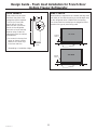
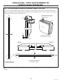
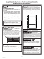
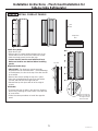
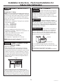
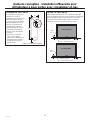
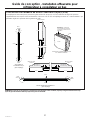
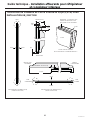
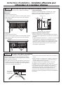
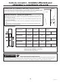
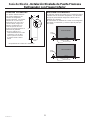
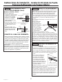
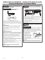
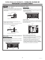
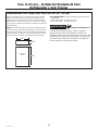
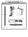
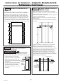
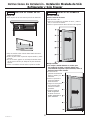
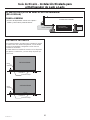
3/4” (1.9 cm) DECORATIVE PANEL
DIMENSIONS
For a more custom
appearance, overlay panels
may be installed to give
a flush appearance with
surrounding cabinets. The
overlay panel must be
3/4” (1.9 cm) thick. Panel
attaches to included brackets
to provide mounting to the
appliance door.
NOTE: We recommend that
decorative panels have inside
corners and edges rounded
or beveled by cabinet maker
to avoid sharp edges on the
panels. Edges to be treated
should include the top, bottom and hinge side edges.
IMPORTANT NOTE: Maximum total weight for the
assembled panels:
• Fresh food door panels – 30 lbs. (14 kg)
• Freezer drawer panel – 28 lbs.(13 kg)
• Grille Panel – 11 lbs. (5 kg)
WARNING
d
Door Trim Pinch Point Hazard
Improper installation can lead to a finger pinch point
hazard between the side door trim and the cabinets
when operating the door, especially with children. To
minimize this risk you must follow the installation
instructions for cabinet dimensions, trim assembly, and
door stop angle.
AVERTISSEMENT
d
Risque de pincement
de doigts
Une installation incorrecte peut poser un risque de coincement
de doigts entre la garniture de porte latérale et les armoires
en actionnant la porte, en particulier pour les enfants.
Pour réduire ce risque, vous devez suivre les instructions
d’installation relatives aux dimensions d’armoire, au montage
des garnitures et à l’angle de l’arrêt de porte.
ADVERTENCIA
d
Riesgo de Lastimadura
con el Marco de la Puerta
Una instalación inadecuada podrá conducir a riesgos de
pellizcos de dedos entre el marco lateral de la puerta y los
gabinetes al utilizar la puerta, especialmente con los niños.
A fin de minimizar este riesgo, usted deberá seguir las
instrucciones de instalación para dimensiones de gabinetes,
ensambles de marcos y ángulos de detención de puertas.
Grille Panel
Fresh
Food
Panel
Fresh
Food
Panel
38"
18-3/4" 18-3/4"
10-13/16"
Freezer Drawer
Panel
22-3/8"
46-7/16"
CUSTOMIZATION BASICS:
Framed Or Overlay Panels, Custom
Handles and Accessory Kits
These refrigerators are designed to be customized with
decorative panels. Field installed custom door and grille
panels are required.
Side Panels
Side panels must be used whenever the sides of the
refrigerator will be exposed.
REFRIGERATOR LOCATION
• Do not install the refrigerator where the temperature
will go below 55°F (13°C). It will not run often enough
to maintain proper temperatures.
• Do not install the refrigerator where temperatures will
go above 100°F (37°C). It will not perform properly.
• Do not install the refrigerator in a location exposed to
water (rain, etc.) or direct sunlight.
• Install it on a floor strong enough to support it fully
loaded.
31-1000454 Rev. 2

10
Design Guide - Flush Inset Installation for French Door
Bottom Freezer Refrigerator
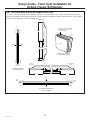
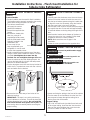
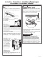
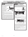
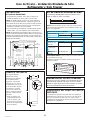
3/4” (1.9 cm) RAISED FRESH FOOD DOOR PANEL ROUTING
For 3/4” (1.9 cm) raised door panels, routing is required. The router depth is 1/4” (0.63 cm) all the way around the
panel back. Additional panel width reductions are required per the diagrams below. This will create a “picture frame”
routing that will slide onto the attached door trim.
1/4”
11/32”
3/16”
3/4” PANEL SIDE VIEW
(AFTER ROUTING)
Front
TOP DETAIL TOP
CORNER VIEW SHOWING
“PICTURE FRAME” ROUTING
DETAIL BOTTOM
BOTTOM
Back
Front
Back
7/16”
3/4”
1/4”
NOTE: Routed areas should be
finished as they may be visible
when assembled.
3/4” PANEL BOTTOM VIEW
(AFTER ROUTING)
HINGE
SIDE
HANDLE
SIDE
Front
Back
DETAIL
HINGE SIDE
DETAIL HANDLE
SIDE
2-1/16” 3/16”
ROUTER DEPTH 1/4”
ROUTER
DEPTH 1/4”
NOTE: For panels constructed with rails and stiles (5-panel), the minimum width is 3” (7.62 cm) for rails and 4” (10.16 cm)
for stiles.
31-1000454 Rev. 2

11
Design Guide - Flush Inset Installation for French Door
Bottom Freezer Refrigerator
3/4” (1.9 cm) RAISED FREEZER DRAWER PANEL ROUTING
For 3/4” (1.9 cm) raised door panel, routing is required. The router depth is 1/4” (0.63 cm) all the way around the
panel back. Additional panel width reductions are required per the diagrams below. This will create a “picture frame”
routing that will slide onto the attached door trim.
1/4”
11/32”
1/4”
3/4” PANEL SIDE VIEW
(AFTER ROUTING)
Front
TOP DETAIL TOP
CORNER VIEW SHOWING
“PICTURE FRAME” ROUTING
DETAIL BOTTOM
BOTTOM
Back
Front
Back
1/2”
3/4”
1/4”
NOTE: Routed areas should be
finished as they may be visible
when assembled.
3/4” PANEL BOTTOM VIEW
(AFTER ROUTING)
LEFT
SIDE
RIGHT
SIDE
Front
Back
DETAIL
LEFT SIDE
DETAIL RIGHT
SIDE
2-1/16” 2-1/16”
ROUTER DEPTH 1/4” ROUTER DEPTH 1/4”
NOTE: For panels constructed with rails and stiles (5-panel), the minimum width is 3” (7.62 cm) for rails and 4” (10.16 cm)
for stiles.
31-1000454 Rev. 2

12
Design Guide - Flush Inset Installation for French Door
Bottom Freezer Refrigerator
3/4” (1.9 cm) RAISED GRILLE PANEL ROUTING
For 3/4” (1.9 cm) raised grille panel, routing is required. The router depth is 1/4” (0.63 cm) all the way around the
panel back. Additional panel width reductions are required per the diagrams below. This will create a “picture frame”
routing that will slide onto the attached grille trim.
3/4” PANEL SIDE VIEW
(AFTER ROUTING)
3/4” PANEL BOTTOM VIEW
(AFTER ROUTING)
Front
TOP
DETAIL TOP
CORNER VIEW SHOWING
“PICTURE FRAME” ROUTING
DETAIL BOTTOM
BOTTOM
LEFT
SIDE
RIGHT
SIDE
DETAIL
LEFT SIDE
DETAIL RIGHT
SIDE
Back
Front
Back
Front
Back
NOTE: Routed areas should be
finished as they may be visible
when assembled.
2-1/16” 2-1/16”
ROUTER DEPTH 1/4” ROUTER DEPTH 1/4”
1/4”
1-11/16”
ROUTER DEPTH 1/4”
NOTE: For panels constructed with rails and stiles (5-panel), the minimum width is 3” (7.62 cm) for rails and 4” (10.16 cm)
for stiles.
31-1000454 Rev. 2

13
Design Guide - Flush Inset Installation for French Door
Bottom Freezer Refrigerator
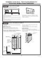
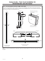
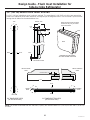
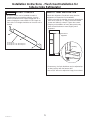
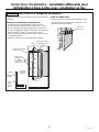
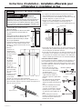
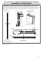
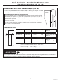
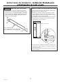
SIDE PANELS
Side panels must be used
whenever the sides of the
refrigerator will be exposed.
The 1/4” (0.63 cm) side
panels will slip into the
side case trim. Secure the
panels to the refrigerator
with stick-on hook and loop
fastener strips. Order the
side panels from the cabinet
manufacturer.
• Cut a notch in the top front
corner as shown to allow
clearance for corner keys
in the front side trim.
* Depending on installation height.
*84"
2-9/16"
24"
*3" to 4"
3/16"
1-7/8"
SIDE CLEATS
Wood cleats are required to be installed vertically down
both sides of the cabinet opening to provide depth stop
for the refrigerator when installed into the opening.
The cleat should be installed per the diagrams below
based on the type of panel being used.
5-1/4”
Finished
Cleat
Case Trim
1/2”
3/4” Panel
DOOR
TOP VIEW
5-3/8”
Finished
Cleat
Case Trim
1/2”
1/2” Panel
DOOR
TOP VIEW
31-1000454 Rev. 2

14
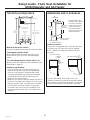
Installation Instructions - Flush Inset Installation for
French Door Bottom Freezer Refrigerator
GROUNDING THE REFRIGERATOR
WARNING
Electrical Shock Hazard.
Failure to follow these instructions can result in death,
fire, or electrical shock.
The power cord of this appliance is equipped with a
3-prong (grounding) plug which mates with a standard
3-prong (grounding) wall receptacle to minimize the
possibility of electric shock hazard from this appliance.
Have the wall outlet and circuit checked by a qualified
electrician to make sure the outlet is properly grounded.
Where a standard 2-prong wall outlet is encountered, it
is your personal responsibility and obligation to have it
replaced with a properly grounded 3-prong wall outlet.
DO NOT, UNDER ANY CIRCUMSTANCES, CUT OR
REMOVE THE THIRD (GROUND) PRONG FROM THE
POWER CORD.
DO NOT USE AN ADAPTER
PLUG TO CONNECT THE
REFRIGERATOR TO A 2-PRONG
OUTLET.
DO NOT USE AN EXTENSION
CORD WITH THIS APPLIANCE.
MISE À LA TERRE DU
RÉFRIGÉRATEUR
AVERTISSEMENT
Risque de choc
électrique.
Le non-respect de ces instructions peut entraîner des risques
d’incendies, des chocs électriques ou la mort.
Le cordon d’alimentation de cet appareil est équipé d’une
fiche à trois broches (pour une mise à la terre) qui s’adapte à
la prise de courant standard à 3 broches (pour une mise à la
terre) pour minimiser les risques de chocs électriques par cet
appareil.
Faites vérifier la prise murale et le circuit électrique par
un électricien qualifié pour s’assurer que le système est
correctement mis à la terre.
Dans le cas d’une prise biphasée, l’installateur a la
responsabilité et l’obligation de la remplacer par une prise
triphasée correctement mise à la terre.
NE COUPEZ PAS OU N’ENLEVEZ PAS, SOUS
AUCUN PRÉTEXTE, LA TROISIÈME BROCHE DE
MISE À LA TERRE DU CORDON
D’ALIMENTATION.
N’UTILISEZ PAS D’ADAPTATEUR
POUR BRANCHER LE
RÉFRIGÉRATEUR À UNE PRISE
BIPHASÉE.
N’UTILISEZ PAS DE RALLONGE AVEC
CET APPAREIL.
TOOLS REQUIRED
• Tinsnips to cut banding • Stepladder
• Bucket • Level
• Appliance Hand Truck • Tubing cutter
• 7/16” open-end wrench • #2 Phillips screwdriver
• Drill and appropriate bits • 5/16”, 7/16” socket
• Safety glasses • 1-1/4” open end wrench
• Pliers • 1/4” ratchet
HARDWARE SUPPLIED WITH UNIT
• Water filter bypass plug
• Anti-Tip brackets
• 1/4” nut and ferrule
MATERIALS REQUIRED
• 35” (88.9 cm) long 2x4 for Anti-Tip support
• 1/4” copper water line tubing or SmartConnect
™
Refrigerator Tubing kits
• Water shut-off valve
• Custom panels for fresh food door, freezer drawer and
grille panel
• Screws to secure refrigerator to cabinetry.
• Stick-on hook and loop fastener strips for
1/4” (0.63 cm) side panels
• ZKFN Kit required for all flush inset installation
FLOORING
For proper installation, this refrigerator must be placed
on a level surface of hard material that is at the same
height as the rest of the flooring. This surface should be
strong enough to support a fully loaded refrigerator, or
approximately 1,200 lbs. (544.31 cm).
NOTE: Protect the finish of the flooring. Cut a large
section of the cardboard carton and place under the
refrigerator where you are working.
31-1000454 Rev. 2

15
Installation Instructions - Flush Inset Installation for
French Door Bottom Freezer Refrigerator
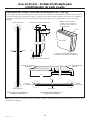
STEP 2 INSTALL WATER LINE
WARNING
Connect to potable water supply
only.
AVERTISSEMENT
Raccordez l’appareil à une
alimentation d’eau potable seulement.
ADVERTENCIA
Realice la conexión a un
suministro de agua potable únicamente.
• A cold water supply is required for automatic icemaker
operation. The water pressure must be between 40
and 120 p.s.i. (275-827 kPa).
• Route 1/4” OD copper or SmartConnect
™
plastic
tubing between house cold water line and the water
connection location.
• Tubing should be long
enough to extend to the
front of the refrigerator.
Allow enough tubing
to accommodate bend
leading into the water line connection.
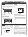
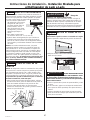
STEP 1 REMOVE PACKAGING
WARNING
Tip Over Hazard.
Refrigerator is much heavier at the top than at the
bottom. To avoid a risk of death or serious injury,
be careful when moving, and when using a hand
truck, handle only from side.
DO NOT ATTEMPT TO ROLL UNIT OFF SKID.
AVERTISSEMENT
Risque de
basculement Parce que le haut du réfrigérateur est
plus lourd que sa base, la prudence est de mise lors son
déplacement, de l’utilisation d’un diable-brouette, de sa
manipulation faite seulement sur son côté afin d’éviter les
blessures graves ou mortelles.
IL NE FAUT PAS ESSAYER DE FAIRE ROULER
L’APPAREIL MÉNAGER POUR L’ENLEVER DE LAY
PALETTE.
ADVERTENCIA
Riesgo de Caídas
El refrigerador es mucho más pesado en su parte superior
que en su parte inferior – tenga cuidado al moverlo. Al
usar un carro manual, sosténgalo de costado únicamente.
NO INTENTE HACER RODAR LA UNIDAD FUERA DEL
ANTIDESLIZANTE.
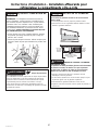
STEP 1 REMOVE PACKAGING
(Cont.)
• Carefully cut banding at the top and bottom, remove
the outer carton.
• Slide out the back corner posts (2).
• Slide the carton off the top of the cabinet.
NOTE: IT IS NOT
NECESSARY TO
LAY THE CABINET
DOWN IN ORDER TO
REMOVE THE SKID!
• The unit is secured
to the skid with 2
full-length tie-down
straps. Remove the
ten 5/16” bolts from
the base channels in
the tie-downs.
• Remove the four
7/16” bolts securing the straps to the skid.
NOTE: DO NOT ATTEMPT TO ROLL UNIT OFF SKID.
• The support blocks on the bottom of the refrigeration
case must be removed before the refrigerator is taken
off the skid or damage will occur. Carefully tilt the
refrigerator and slide the blocks out from beneath.
• Remove the toekick and set aside for final installation.
• Lift the refrigerator off the skid with an appliance dolly.
Floor
Waterline Tubing
CONEXIÓN A TIERRA DEL
REFRIGERADOR
ADVERTENCIA
Riesgo de Descarga
Eléctrica
Si no se siguen estas instrucciones, se podrá producir la
muerte, incendios o descargas eléctricas.
El cable de corriente de este electrodoméstico cuenta con
un enchufe de 3 cables (conexión a tierra) que se conecta a
un tomacorriente de pared estándar de 3 cables (conexión
a tierra) para minimizar el riesgo de posibles descargas
eléctricas por parte del mismo.
Contrate a un electricista calificado para que controle el
tomacorriente y el circuito eléctrico, a fin de asegurar que el
enchufe esté correctamente conectado a tierra.
En caso de contar con un tomacorriente de pared de 2
cables, es su responsabilidad y obligación reemplazarlo
por un tomacorriente de pared de 3 cables correctamente
conectado a tierra.
NUNCA, BAJO NINGUNA CIRCUNSTANCIA, CORTE NI
ELIMINE EL TERCER CABLE (TIERRA) DEL CABLE DE
CORRIENTE.
NO USE UN ENCHUFE ADAPTADOR PARA
CONECTAR EL REFRIGERADOR A UN
TOMACORRIENTE DE 2 PATAS.
NO USE UN PROLONGADOR CON ESTE
ELECTRODOMÉSTICO.
CUSTOM HADNLE TRIM KIT
CASE TRIM
Remove 2 strap bolts on
each side
Remove 5 base
channel bolts on
each side
31-1000454 Rev. 2

16
Installation Instructions - Flush Inset Installation for
French Door Bottom Freezer Refrigerator
NOTE: Commonwealth of Massachusetts Plumbing
Codes 248CMR shall be adhered to. Saddle valves
are illegal and use is not permitted in Massachusetts.
Consult with your licensed plumber.
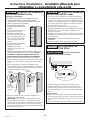
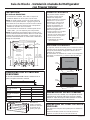
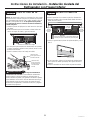
STEP 5 ANTI-TIP PROCEDURE
WARNING
Tip Over Hazard.
These refrigerators are top heavy, especially with any
doors open, and must be secured to prevent tipping
forward which could result in death or serious injury.
Read and follow the entire installation instructions for
securing the refrigerator with the anti-tip system.
AVERTISSEMENT
Risque de
basculement
Ces réfrigérateurs présentent une partie supérieure lourde,
en particulier avec une porte ouverte; ils doivent donc être
fixés pour prévenir le basculement vers l’avant et le risque
concomitant de blessure grave ou fatale. Lisez et suivez
les instructions d’installation complètes pour l’installation du
système anti-basculement.
ADVERTENCIA
Riesgo de Caídas
Estos refrigeradores son inestables, especialmente
cuando una puerta se encuentre abierta, y deberán estar
asegurados a fin de evitar caídas hacia adelante que
podrían resultar en la muerte o en lesiones graves. Lea y
siga las instrucciones de instalación en su totalidad para
asegurar el refrigerador con el sistema anti volcaduras.
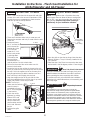
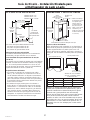
STEP 3 INSTALL SIDE PANELS
Skip this step when not using side panels
If you are using 1/4” (0.63 cm) side panels, they should
be inserted into the case trim. Fasten the panels to the
refrigerator with stick-on hook and loop fastener strips
before setting refrigerator in place.
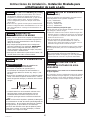
STEP 2A WATER LINE
INSTALLATION WITH A REVERSE
OSMOSIS SYSTEM
Skip this step when not using an RO System
If the water supply to the refrigerator is from a Reverse
Osmosis Water System, use the refrigerator’s filter
bypass plug. Using the refrigerator’s water filtration
cartridge with the RO filter can result in hollow ice
cubes.
Filter Bypass Plug
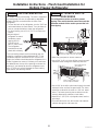
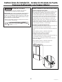
STEP 4 INSTALL CASE TRIM
The unit arrives with case
trim for standard installation
attached. Flush installation
case trim is provided in
kit ZKFN. Remove the
factory installed case trim.
Install new case trim using
supplied right hand and left
hand case trim pieces and
case trim screws. Attach
case trim to each side of
case as shown in illustration
using case trim screws
in holes provided down
each side of the case. The
cutouts on the case trim
should align with the lower
fresh food door hinges.
STEP 2 INSTALL WATER LINE
(Cont.)
NOTE: The only Monogram Appliances-approved
plastic tubing is supplied in the SmartConnect
™
Refrigerator Tubing kits. Do not use any other plastic
water supply line because the line is under pressure at
all times. Other types of plastic may crack or rupture
with age and cause water damage to your home.
SmartConnect
™
Refrigerator Tubing Kits are available in
the following lengths:
2‘ (.6 m) WX08X10002
8’ (2.4 m) WX08X10006
15’ (4.6 m) WX08X1 0015
25’ (7.6 m) WX08X10025
Shut off the main water supply.
Turn on the nearest faucet long enough to clear the line
of water.
• Install a shut-off valve between the icemaker water
valve and cold water pipe in a basement or cabinet.
The shut-off valve should be located where it will be
easily accessible.
• Turn on the main water supply and flush debris.
Run about a quart of water through the tubing into a
bucket. Shut off water supply at the shut-off valve.
NOTE: Saddle type shut-off valves are included in
many water supply kits, but are not recommended for
this application.
31-1000454 Rev. 2

17
Installation Instructions - Flush Inset Installation for
French Door Bottom Freezer Refrigerator
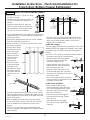
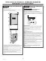
STEP 5 ANTI-TIP PROCEDURE (cont.)
• Cut a 1” (2.54 cm) x 4” (10.16 cm) block,
35” (88.9 cm) long.
• Measure and mark under the soffit, 5-1/4”
(13.33 cm) from the front edge of the
cabinet.
• Secure the wood block to under the
soffit. From the bottom of the block to
the finished floor should measure 84”
(213.36 cm). See the illustration.
• The kit supplied with the unit contains 2 lag bolts and 4
toggles with bolts. The wall bracket will be attached to
the wall in 4 places.
• Measure the opening where the unit is to be installed.
Mark the center with a vertical line.
• Measure up 81-1/2” (207.01 cm) from the floor. Mark
this point on the wall.
• Using a level, draw a
horizontal line on the
wall at this height.
• Locate at least 2
studs on the back
wall. Mark these
points on the
horizontal line.
• Place the bottom
of the wall bracket
with tabs on the
horizontal line. Align
the center notch on
the bracket with the
center line on the
wall.
• The anti-tip wall bracket has a series of holes. Select 2
holes that match with the located studs. Make sure the
holes selected are on the center of the studs. Mark the
wall at these points.
• Mark an additional hole at each end of the bracket.
If one of the studs is closer to the end of the bracket,
mark an additional hole towards the center of the
bracket.
• Drill 1/2” (1.27 cm) holes into the wall board at the
locations marked for the toggles to be mounted (not the
stud markings).
• Drill 3/16” (0.47 cm) holes into wooden studs where
marked. If steel stud construction, drill 1/2” (1.27 cm)
holes into the studs where marked. You will use 2
toggles with the metal studs.
Install Wall Toggles:
The wall toggles and bolts can be ordered as Service Kit
#WR49X10193. Wall toggles are installed in the drywall
and metal studs for stability. Install the wall toggles as
follows:
• Drill 1/2” (1.27 cm) holes at the wall markings made in
the holes at the ends of the wall bracket.
• Hold the metal channel flat against
the plastic straps and slide the
channel through the hole.
• Gently pull back at the ends of the
plastic straps to make the channel
rest flush behind the wall.
• Hold the ends of the straps in one
hand and slide the plastic cap along
the straps until the flange of the cap is
flush with the wall.
• Place your thumb between the plastic
straps and bend up and down to snap
the straps off at the wall.
Install Screws and Bolts:
• Have someone hold the wall
bracket centered in place with each
of the holes aligned with the correct
opening in the bracket and level
with the horizontal line.
• Insert the lag screws through the
bracket and into the stud. Tighten
with a wrench.
• Insert the bolts into the toggle
by hand until snug. Tighten with
a wrench.
Line on Wall
Center
Anti-Tip Wall Bracket
Bolt
Wall Toggle
Drywall or
Steel Stud
Plastic Straps
Metal Channel
Wood Stud
Lag Screw
Anti-Tip Wall Bracket
Cap
Two Additional
Hole Locations at
Ends of Brackets
Center
Wall Bracket
Line On Wall
Wall Studs
81-1/2”
To Floor
31-1000454 Rev. 2

18
Installation Instructions - Flush Inset Installation for
French Door Bottom Freezer Refrigerator
STEP 5 ANTI-TIP PROCEDURE
(CONT)
CONNECT POWER CORD:
• Before pushing the refrigerator into the opening, plug
the power cord into the receptacle. Open the grille
panel and reach into the opening at the back to grasp
the power cord. Pull the power cord into the opening
as you push the refrigerator back.
• Gently push refrigerator into the opening with hands
against front corners.
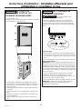
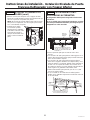
IMPORTANT: When the refrigerator is installed under
a soffit or if there is not enough height for this method
of security, brackets cannot be used. Proceed to step
6 to level the refrigerator and then to step 8 to secure
refrigerator to cabinets.
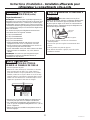
STEP 6 LEVEL REFRIGERATOR
All models have 4-point leveling. The front is supported
by leveling legs, the rear is supported by adjustable
wheels. Both are accessible from the front of the
refrigerator.
• To level the back of the refrigerator, turn the 7/16” hex
nut located above the front wheels. Turn clockwise to
raise or counterclockwise to lower the refrigerator.
• For front leveling, use a 1-1/4” open-end wrench.
• Adjust height of
refrigerator to match
installation cutout opening
83-1/2” (212.09 cm) to
84-1/2” (10.16 cm). The
refrigerator should be
level and plumb with
cabinetry.
The rear leveling wheels and front leveling legs are
limited to a maximum height adjustment of 1” (2.54 cm).
If the installation requires more than 84-1/2” (214.63
cm) height, the installer should elevate the refrigerator
on a sheet of plywood or runners. Cabinetry trim could
also be added across the top of the opening to shorten
the opening. If you attempt to raise the refrigerator
more than 1” (2.54 cm), you will damage the front
leveling legs and the rear leveling wheels.
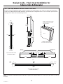
STEP 7 SECURE UNIT TO WALL
• The “L” rod can be found in the upper left corner of
the unit in the access compartment. Look through the
access compartment to make sure the rod lines up
with the anti-tip bracket.
• There are 2 washers and a hair pin cotter with the rod.
Remove the washers and hair pin cotter from the end
of the rod.
• Rotate and move the “L” rod into the slot in the anti-
tip bracket tab. Once it is in the slot, rotate the “L” rod
so the hook portion is pointing down. The holes at the
front end of the rod should be in a vertical position.
• Pull out on the end of the rod to make sure it is secure
in the bracket.
• Locate the hole on the rod that is closest to the unit.
A hair pin cotter will be put through this hole to secure
the rod. If this hole appears to be too far away for a
snug fit against the unit, add the washers one at a
time until the pin will fit tightly into the hole.
• Align the straight section of the pin with the hole from
the underside of the rod. Push the pin up until it snaps
into position. Pliers may be used. NOTE: The hair pin
cotter must be vertical when this step is completed to
ensure the “L” rod is engaged in the bracket.
• Check the rod for tightness by pulling forward. If the
rod moves, remove the hair pin cotter and place
another washer on the rod. Reinsert the pin.
31-1000454 Rev. 2

19
Installation Instructions - Flush Inset Installation for
French Door Bottom Freezer Refrigerator
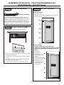
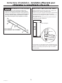
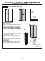
STEP 8 ALTERNATE ANTI-TIP
PROCEDURE
The refrigerator must be secured to prevent tipping.
If the anti-tip bracket cannot be used, this alternate
procedure may be used to secure the refrigerator
against tip-over
• Raise the grille panel to access case trim.
• Use a 3/16” bit to drill four evenly spaced clearance
holes through the metal top case trim.
• Use a 1/16” bit to drill to pilot holes through the metal
clearance holes and into the wood soffit. The holes
should be centered in the soffit or a 3/4” min. wood
brace. The brace spanning the enclosure must be
securely fastened to cabinets on both sides.
• Install four, 1-1/2” (3.81 cm) drywall screws into the
pilot holes.
• If no soffit above the unit, drill screws into adjacent
cabinets through the side case trim.
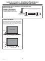
STEP 9 ADJUST DOOR SWING
• Lift the grille panel to access the wire cover trim.
• Remove screws on both sides of the wire cover trim
and rotate off.
• Use pliers to unscrew door stop and reinstall into the
90° or 130° position.
• Reinstall the wire cover trim.
WARNING
d
Door Trim Pinch Point Hazard
Improper installation can lead to a finger pinch point
hazard between the side door trim and the cabinets
when operating the door, especially with children.
To minimize this risk you must follow the installation
instructions for cabinet dimensions, trim assembly, and
door stop angle.
AVERTISSEMENT
d
Risque de pincement
de doigts
Une installation incorrecte peut poser un risque de
coincement de doigts entre la garniture de porte latérale
et les armoires en actionnant la porte, en particulier pour
les enfants. Pour réduire ce risque, vous devez suivre les
instructions d’installation relatives aux dimensions d’armoire,
au montage des garnitures et à l’angle de l’arrêt de porte.
ADVERTENCIA
d
Riesgo de Lastimadura con
el Marco de la Puerta : Una instalación inadecuada podrá
conducir a riesgos de pellizcos de dedos entre el marco lateral
de la puerta y los gabinetes al utilizar la puerta, especialmente
con los niños. A fin de minimizar este riesgo, usted deberá
seguir las instrucciones de instalación para dimensiones de
gabinetes, ensambles de marcos y ángulos de detención de
puertas.
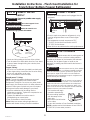
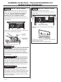
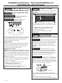
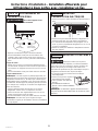
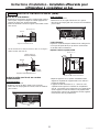
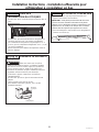
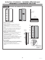
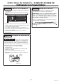
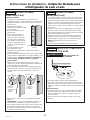
STEP 9 ADJUST DOOR SWING
NOTE: This refrigerator has a 3-position door stop.
When space does not allow the door to swing open
fully to 115°, you may change the door swing to
a 90° opening. A 130° door swing is available for
standard installation only. If used for flush installation,
damage will occur to wood panels. Skip this step if
door opening is satisfactory for your installation
situation.
Remove
Wire Cover
Trim Screws
Pin Location for
90° Door Swing
Pin Location for
130° Door Swing -
Not for use with
Flush Installation
Pin Location
as Shipped for
115°
Door Swing
31-1000454 Rev. 2

20
Installation Instructions - Flush Inset Installation for
French Door Bottom Freezer Refrigerator
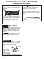
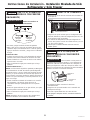
STEP 10 INSTALL GRILLE PANEL
• Raise the access panel to the stop position.
• Loosen the screws on the side trim behind the frame.
Remove the bottom trim.
• Slide the panel over the metal baker panel and into the
trim.
• If necessary, tap with a wood block until the panel slips
under the top trim piece.
• Reassemble the bottom trim. Tighten the screws.
• Adjust the hinge spring to accommodate the panel
weight, if necessary.
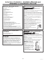
STEP 11
INSTALL ASSEMBLED PANELS
• Install custom handles according to the manufacturer’s
instructions.
FRESH FOOD DOORS
• Beginning with the right fresh food door, slide
assembled door panel into the trim on the door.
• Place the custom handle trim against the side of the
refrigerator door, aligned top to bottom. The holes in the
trim should align to the holes in the door.
• Attach the custom handle trim with the 8 screws
previously removed.
• Repeat these steps with the left fresh food door.
FREEZER DRAWER
• Slide the assembled panel into the drawer trim.
• Secure the original drawer trim using the original round
head trim screws.
Door Trim and
8 Screws
2-sided
Mylar
Tape
Flange
Trim
Cover
Door
Handle
Trim
Shims
Flange Trim Cover
and 4 Screws
Custom Handle
Trim and 4 Screws
Shims
Double-Sided
Mylar Tape
Located
on Back of
Flange Trim
Cover
31-1000454 Rev. 2
La page est en cours de chargement...
La page est en cours de chargement...
La page est en cours de chargement...
La page est en cours de chargement...
La page est en cours de chargement...
La page est en cours de chargement...
La page est en cours de chargement...
La page est en cours de chargement...
La page est en cours de chargement...
La page est en cours de chargement...
La page est en cours de chargement...
La page est en cours de chargement...
La page est en cours de chargement...
La page est en cours de chargement...
La page est en cours de chargement...
La page est en cours de chargement...
La page est en cours de chargement...
La page est en cours de chargement...
La page est en cours de chargement...
La page est en cours de chargement...
La page est en cours de chargement...
La page est en cours de chargement...
La page est en cours de chargement...
La page est en cours de chargement...
La page est en cours de chargement...
La page est en cours de chargement...
La page est en cours de chargement...
La page est en cours de chargement...
La page est en cours de chargement...
La page est en cours de chargement...
La page est en cours de chargement...
La page est en cours de chargement...
La page est en cours de chargement...
La page est en cours de chargement...
La page est en cours de chargement...
La page est en cours de chargement...
La page est en cours de chargement...
La page est en cours de chargement...
La page est en cours de chargement...
La page est en cours de chargement...
La page est en cours de chargement...
La page est en cours de chargement...
La page est en cours de chargement...
La page est en cours de chargement...
La page est en cours de chargement...
La page est en cours de chargement...
La page est en cours de chargement...
La page est en cours de chargement...
La page est en cours de chargement...
La page est en cours de chargement...
La page est en cours de chargement...
La page est en cours de chargement...
La page est en cours de chargement...
La page est en cours de chargement...
La page est en cours de chargement...
La page est en cours de chargement...
La page est en cours de chargement...
La page est en cours de chargement...
La page est en cours de chargement...
La page est en cours de chargement...
La page est en cours de chargement...
La page est en cours de chargement...
La page est en cours de chargement...
La page est en cours de chargement...
La page est en cours de chargement...
La page est en cours de chargement...
La page est en cours de chargement...
La page est en cours de chargement...
La page est en cours de chargement...
La page est en cours de chargement...
La page est en cours de chargement...
La page est en cours de chargement...
La page est en cours de chargement...
La page est en cours de chargement...
La page est en cours de chargement...
La page est en cours de chargement...
La page est en cours de chargement...
La page est en cours de chargement...
La page est en cours de chargement...
La page est en cours de chargement...
La page est en cours de chargement...
La page est en cours de chargement...
La page est en cours de chargement...
La page est en cours de chargement...
La page est en cours de chargement...
La page est en cours de chargement...
La page est en cours de chargement...
La page est en cours de chargement...
La page est en cours de chargement...
La page est en cours de chargement...
La page est en cours de chargement...
La page est en cours de chargement...
La page est en cours de chargement...
La page est en cours de chargement...
La page est en cours de chargement...
La page est en cours de chargement...
La page est en cours de chargement...
La page est en cours de chargement...
La page est en cours de chargement...
La page est en cours de chargement...
La page est en cours de chargement...
La page est en cours de chargement...
La page est en cours de chargement...
La page est en cours de chargement...
La page est en cours de chargement...
La page est en cours de chargement...
La page est en cours de chargement...
La page est en cours de chargement...
La page est en cours de chargement...
La page est en cours de chargement...
La page est en cours de chargement...
La page est en cours de chargement...
La page est en cours de chargement...
La page est en cours de chargement...
La page est en cours de chargement...
La page est en cours de chargement...
La page est en cours de chargement...
La page est en cours de chargement...
La page est en cours de chargement...
La page est en cours de chargement...
La page est en cours de chargement...
La page est en cours de chargement...
La page est en cours de chargement...
La page est en cours de chargement...
La page est en cours de chargement...
La page est en cours de chargement...
La page est en cours de chargement...
La page est en cours de chargement...
La page est en cours de chargement...
La page est en cours de chargement...
La page est en cours de chargement...
La page est en cours de chargement...
La page est en cours de chargement...
La page est en cours de chargement...
La page est en cours de chargement...
La page est en cours de chargement...
La page est en cours de chargement...
La page est en cours de chargement...
La page est en cours de chargement...
La page est en cours de chargement...
La page est en cours de chargement...
La page est en cours de chargement...
La page est en cours de chargement...
La page est en cours de chargement...
La page est en cours de chargement...
La page est en cours de chargement...
La page est en cours de chargement...
La page est en cours de chargement...
La page est en cours de chargement...
La page est en cours de chargement...
La page est en cours de chargement...
La page est en cours de chargement...
La page est en cours de chargement...
La page est en cours de chargement...
La page est en cours de chargement...
La page est en cours de chargement...
La page est en cours de chargement...
La page est en cours de chargement...
La page est en cours de chargement...
La page est en cours de chargement...
La page est en cours de chargement...
La page est en cours de chargement...
La page est en cours de chargement...
La page est en cours de chargement...
La page est en cours de chargement...
La page est en cours de chargement...
La page est en cours de chargement...
La page est en cours de chargement...
La page est en cours de chargement...
La page est en cours de chargement...
La page est en cours de chargement...
La page est en cours de chargement...
La page est en cours de chargement...
La page est en cours de chargement...
La page est en cours de chargement...
La page est en cours de chargement...
La page est en cours de chargement...
La page est en cours de chargement...
La page est en cours de chargement...
La page est en cours de chargement...
La page est en cours de chargement...
La page est en cours de chargement...
La page est en cours de chargement...
La page est en cours de chargement...
La page est en cours de chargement...
La page est en cours de chargement...
La page est en cours de chargement...
La page est en cours de chargement...
La page est en cours de chargement...
La page est en cours de chargement...
La page est en cours de chargement...
La page est en cours de chargement...
La page est en cours de chargement...
La page est en cours de chargement...
La page est en cours de chargement...
La page est en cours de chargement...
La page est en cours de chargement...
La page est en cours de chargement...
La page est en cours de chargement...
La page est en cours de chargement...
-
 1
1
-
 2
2
-
 3
3
-
 4
4
-
 5
5
-
 6
6
-
 7
7
-
 8
8
-
 9
9
-
 10
10
-
 11
11
-
 12
12
-
 13
13
-
 14
14
-
 15
15
-
 16
16
-
 17
17
-
 18
18
-
 19
19
-
 20
20
-
 21
21
-
 22
22
-
 23
23
-
 24
24
-
 25
25
-
 26
26
-
 27
27
-
 28
28
-
 29
29
-
 30
30
-
 31
31
-
 32
32
-
 33
33
-
 34
34
-
 35
35
-
 36
36
-
 37
37
-
 38
38
-
 39
39
-
 40
40
-
 41
41
-
 42
42
-
 43
43
-
 44
44
-
 45
45
-
 46
46
-
 47
47
-
 48
48
-
 49
49
-
 50
50
-
 51
51
-
 52
52
-
 53
53
-
 54
54
-
 55
55
-
 56
56
-
 57
57
-
 58
58
-
 59
59
-
 60
60
-
 61
61
-
 62
62
-
 63
63
-
 64
64
-
 65
65
-
 66
66
-
 67
67
-
 68
68
-
 69
69
-
 70
70
-
 71
71
-
 72
72
-
 73
73
-
 74
74
-
 75
75
-
 76
76
-
 77
77
-
 78
78
-
 79
79
-
 80
80
-
 81
81
-
 82
82
-
 83
83
-
 84
84
-
 85
85
-
 86
86
-
 87
87
-
 88
88
-
 89
89
-
 90
90
-
 91
91
-
 92
92
-
 93
93
-
 94
94
-
 95
95
-
 96
96
-
 97
97
-
 98
98
-
 99
99
-
 100
100
-
 101
101
-
 102
102
-
 103
103
-
 104
104
-
 105
105
-
 106
106
-
 107
107
-
 108
108
-
 109
109
-
 110
110
-
 111
111
-
 112
112
-
 113
113
-
 114
114
-
 115
115
-
 116
116
-
 117
117
-
 118
118
-
 119
119
-
 120
120
-
 121
121
-
 122
122
-
 123
123
-
 124
124
-
 125
125
-
 126
126
-
 127
127
-
 128
128
-
 129
129
-
 130
130
-
 131
131
-
 132
132
-
 133
133
-
 134
134
-
 135
135
-
 136
136
-
 137
137
-
 138
138
-
 139
139
-
 140
140
-
 141
141
-
 142
142
-
 143
143
-
 144
144
-
 145
145
-
 146
146
-
 147
147
-
 148
148
-
 149
149
-
 150
150
-
 151
151
-
 152
152
-
 153
153
-
 154
154
-
 155
155
-
 156
156
-
 157
157
-
 158
158
-
 159
159
-
 160
160
-
 161
161
-
 162
162
-
 163
163
-
 164
164
-
 165
165
-
 166
166
-
 167
167
-
 168
168
-
 169
169
-
 170
170
-
 171
171
-
 172
172
-
 173
173
-
 174
174
-
 175
175
-
 176
176
-
 177
177
-
 178
178
-
 179
179
-
 180
180
-
 181
181
-
 182
182
-
 183
183
-
 184
184
-
 185
185
-
 186
186
-
 187
187
-
 188
188
-
 189
189
-
 190
190
-
 191
191
-
 192
192
-
 193
193
-
 194
194
-
 195
195
-
 196
196
-
 197
197
-
 198
198
-
 199
199
-
 200
200
-
 201
201
-
 202
202
-
 203
203
-
 204
204
-
 205
205
-
 206
206
-
 207
207
-
 208
208
-
 209
209
-
 210
210
-
 211
211
-
 212
212
-
 213
213
-
 214
214
-
 215
215
-
 216
216
-
 217
217
-
 218
218
-
 219
219
-
 220
220


dans d''autres langues
- English: GE ZKFN Installation guide
- español: GE ZKFN Guía de instalación
Documents connexes
-
GE ZWE23PSNSS Guide d'installation
-
GE ZIFS360NHBRH Guide d'installation
-
-
-
GE ZIC360NHRH Guide d'installation
-
-
GE ZIR360NNLH Guide d'installation
-
-
Autres documents
-
 GE Monogram ZIRS360NBRH Guide d'installation
-
Monogram ZIPP360NHSS Guide d'installation
-
-
-
-
-
-
 Brainerd H0103AV-W-O2 Guide d'installation
-
-

