Intellinet 561426 Quick Instruction Guide
- Taper
- Quick Instruction Guide

Important: Read before use. • Importante: Leer antes de usar.
Scan to
register your
product warranty
24-Port Gigabit Ethernet PoE+ Web-
Managed Switch with 4 Gigabit
Combo Base-T/SFP Ports Instructions
Model 561426-V3 (IPS-28GM04-370W)
For additional benets:
or go to: register.intellinet-network.com/r/561426

2
This guide presents the basic steps to set up and operate this device.
For the user manual and specifications, visit intellinetnetwork.com. Register your
product at register.intellinet-network.com/r/561426 or scan the QR code on the cover.
Placement
Prior to use, it is recommended that the switch be placed/positioned:
• on a level surface that can support the weight of the switch
(and any other items that need to be considered);
• with a minimum of 25 mm (approx. 1”) of clearance on
the top and sides for adequate ventilation;
• away from sources of electrical noise: radios,
transmitters, broadband amplifiers, etc.;
• within 100 m (approx. 328’) of network devices it’s to be connected to;
• where it cannot be affected by excessive moisture.
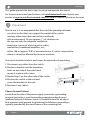
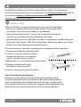
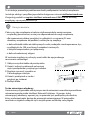
The switch includes brackets and screws for optional rack mounting.
1 Disconnect any cables from the switch.
2 Position a bracket over the mounting
holes on one side of the switch and
secure it in place with screws.
3 Repeat Step 2 on the other side of the switch.
4 Position the switch in the rack and
screw the brackets to the rack.
5 Reconnect any cables.
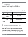
Chassis Ground Column
Located on the side of the power supply connector, a grounding
terminal connector is used to provide proper grounding for your
Intellinet Network Solutions switch. It should be wired to an object
that provides earth ground. In rackmount installations, grounding is
typically provided by the metal frame of the mounting rack.
English
Instructions

3
English
Connections
• All ports on the switch support Auto-MDI/MDI-X functionality,
so you can use straight or crossover UTP/STP cables to connect
the RJ45 ports to PCs, routers, hubs, other switches, etc.
• Use the included power cable to connect the receptacle on the back of
the switch to a power outlet, and confirm that the Power LED lights.
• Cat5e/6/6a/8.x UTP/STP cables provide optimal performance;
if a status LED doesn’t indicate a link or activity, check the
corresponding device for proper setup and operation.
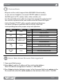
LED Color Status Operation
PWR Green On Unit is receiving power.
Off Check connection.
SYS Green Blinking System is booting or has booted successfully.
Off System not started.
Link / Act
1–24, 25T–28T
10/100M: Orange;
1000M: Green
On Valid port connection.
Blinking Data transmitted/received.
Off No link established.
PoE
1 – 24 Orange
On The connected device is receiving power.
Blinking Abnormal power supply.
Off No PD device is linked.
25S–28S
(SFP) Green
On Valid port connection.
Blinking Data transmitted/received.
Off No link established.
Basic Web-Based Browser Management
1 Open your Web browser.
2 Enter http:// and the IP address of the switch in the Address
field. The default management IP address is 192.168.2.1.
3 Press Enter to display the login screen. In the Username field, enter admin; in the
Password field, enter the serial number on the bottom of the switch. Click OK.
Instructions

4
Anleitung
Deutsch
Diese Kurzanleitung zeigt die grundlegenden Schritte zur
Einrichtung und Inbetriebnahme dieses Geräts.
Das Benutzerhandbuch und die technischen Daten finden
Sie unter intellinetnetwork.com. Registrieren Sie Ihr
Produkt auf register.intellinet-network.com/r/561426 oder
scannen Sie den QR-Code auf dem Deckblatt.
Nutzungsumgebung
Er wird empfohlen, den Switch vor der Nutzung folgendermaßen aufzustellen:
• auf ebenem Untergrund, der das Gewicht des Switches
(und evtl. anderer Gegenstände) trägt;
• mit mindestens 25 mm Abstand zu allen Seiten für angemessenen Luftdurchsatz;
• fern von anderen Übertragungsgeräten wie Radios, Breitband-verstärker, etc.;
• max. 100 m von den Netzwerkgeräten entfernt, die Sie anschließen möchten;
• nicht in feuchten Umgebungen.
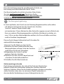
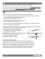
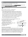
Diesem Switch liegen Haltewinkel und Schrauben für
optionale Rackmontage bei.
1 Trennen Sie alle Kabel von dem Switch.
2 Platzieren Sie einen Haltewinkel über den
Montagelöchern auf einer Seite des Switches
und fixieren Sie ihn mit Schrauben.
3 Wiederholen Sie Schritt 2 auf der
anderen Seite des Switches.
4 Platzieren Sie den Switch in dem Rack und
schrauben Sie die Haltewinkel fest.
5 Schließen Sie alle Kabel wieder an.
Gehäuseerdungsschraube
Der Erdungsendverbinder, der sich auf der Seite des Netzsteckers
befindet, erleichtert die korrekte Erdung des Intellinet Network
Solutions Schalters. Wenn Sie die Gehäuseerdungsschraube verwenden,
stellen Sie bitte sicher, dass sie mit einem Objekt verbunden ist,
das eine direkte Verbindung zu einem Erdungsleiter besitzt.

5
Anschlüsse
• Alle Ports unterstützen Auto-MDI/MDI-X Funktionalität, daher können Sie
ein Crossover- oder Nicht-Crossover UTP-/STP-Kabel verwenden, um die
RJ45-Ports mit PCs, Routern, Hubs, anderen Switchen etc. zu verbinden.
• Verwenden Sie das beiliegende Stromkabel, um die Strombuchse
auf der Rückseite des Switches mit einer Steckdose zu
verbinden und prüfen Sie, dass die Power-LED leuchtet.
• Cat5e/6/6a/8.x- UTP/STP-Kabel bieten die beste Performance. Wenn eine LED
keine Verbindung/Aktivität anzeigt, überprüfen Sie das verbundene Gerät.
LED Farbe Status Bedeutung
PWR Grün An Gerät wird mit Strom versorgt.
Aus Stromanschluss prüfen.
SYS Grün Blinkend Das System startet oder wurde erfolgreich gestartet.
Aus System nicht gestartet.
Link / Act
1–24, 25T–28T
10/100M: Orange;
1000M: Grün
An Verbindung ist hergestellt.
Blinkend Datenübertragung.
Aus Verbindung ist nicht hergestellt.
PoE
1 – 24 Orange
An Das angeschlossene Gerät erhält Strom.
Blinkend Unnormale Spannungsversorgung am Port.
Aus Kein PD-Gerät angeschlossen.
25S–28S
(SFP) Grün
An Verbindung ist hergestellt.
Blinkend Datenübertragung.
Aus Verbindung ist nicht hergestellt.
Grundlagen der Steuerung über den Webbrowser.
1 Öffnen Sie Ihren Webbrowser.
2 Geben Sie http:// und die IP-Adresse des Switches in der
Adresszeile ein. Die Standard-IP-Adresse lautet 192.168.2.1.
3 Drücken Sie Enter, um zum Loginfenster zu gelangen. Geben Sie als
Benutzernamen admin. Geben Sie im Passwort-Feld die Seriennummer ein, die
sich auf dem Aufkleber auf der Unterseite des Switch befindet. Klicken Sie auf OK.
Deutsch
Anleitung

6Español
Esta guía presenta los pasos básicos para instalar y operar este dispositivo.
Para tener el manual de usuario y los requisitos, visita intellinetnetwork.com. Registre
el producto en register.intellinet-network.com/r/561426 o
escanee el código QR en la cubierta.
Colocación
Antes de utilizarlo, se recomienda que el switch sea colocado/fijado:
• Sobre una superficie plana que pueda soportar el peso del switch
(y cualquier otro artículo que deba ser considerado);
• Con un mínimo de 25 mm (1” aprox.) de espacio libre en la parte
superior y en los lados para una ventilación adecuada;
• Apartado de fuentes de ruido eléctrico: radios, transmisores, amplificadores, etc.;
• Dentro de 100 m (aprox. 328’) de los dispositivos de red que deben conectarse;
• Donde no sea afectado por la humedad excesiva.
El switch incluye los soportes y tornillos para su montaje en Rack (opcional).
1 Desconecte cualquier cable del switch.
2 Coloque el soporte sobre los orificios
de montaje, ubicados a un lado del
switch y sujételo con los tornillos.
3 Repita el paso 2 en el lado contrario del switch.
4 Coloque el switch en el rack y
atornille los soportes al rack.
5 Conecte nuevamente todos los cables.
Chasis-Tornillo de toma de tierra
Ubicado en el lado del conector de la fuente de alimentación, el
conector del terminal de tierra facilita la adecuada conexión para el
switch (conmutador) de Intellinet Network Solutions. Cuando utilice
el tornillo de toma de tierra del chasis, asegúrese de engancharlo a un
objeto que proporcione acceso directo a un conductor de tierra.
Instrucciones

7
Conexiónes
• Todos los puertos del switch soportan Auto-MDI/MDI-X, puede
utilizarse cable directo o cruzado UTP/STP para conectar los
puertos RJ45 a la PC, router, hub, otros switches, etc.
• Utilice el cable de corriente incluido para conectar la parte trasera del switch
con una toma de corriente, y confirme que el LED de encendido se ilumina.
• Los cables Cat5e/6/6a/8.x UTP/STP proporcionan un redimiento optimo; Si un LED
no indica conectividad ó actividad, compruebe las conexiones sean adecuadas.
LED Color Estado Operación
PWR Verde Encendido El dispositivo recibe energía.
Apagado Compruebe la conexión.
SYS Verde Parpadeo El sistema se está iniciando o se ha iniciado correctamente.
Apagado Sistema no iniciado.
Link / Act
1–24, 25T–28T
10/100M:
Naranja;
1000M: Verde
Encendido Válida el puerto de conexión.
Parpadeo Datos enviados/recibidos.
Apagado No hay conexión.
PoE
1 – 24 Naranja
Encendido El dispositivo conectado recibe alimentación eléctrica.
Parpadeo Suministro eléctrico anómalo.
Apagado No hay un dispositivo PD conectado.
25S–28S
(SFP) Verde
Encendido Válida el puerto de conexión.
Parpadeo Datos enviados/recibidos.
Apagado No hay conexión.
Administración básica vía Navegador Web
1 Inicie su Navegador Web.
2 Ingrese http:// y la dirección IP del switch en la barra de direcciones.
La dirección de administración por defecto es 192.168.2.1.
3 Presione Enter para ingresar a la pantalla de inicio de sesión. El nombre
de usuario es admin, la contraseña es el número de serie que está en la
etiqueta en la parte inferior del conmutador. Haga clic en OK (Aceptar).
Español
Instrucciones

8Français
Ce guide décrit les bases pour configurer et opérer cet appareil.
Pour obtenir le manuel utilisateur et des spécifications, visitez intellinetnetwork.com.
Enregistrez votre produit sur register.intellinet-network.com/r/561426
ou scannez le code QR figurant sur la couverture.
Placement
Avant d’utiliser le commutateur, il est recommandé de le placer:
• sur une surface plane qui peut supporter son poids (et celui d’autres objets) ;
• ac. un écartement minimal de 25 mm d’autres
objets pour une ventilation suffisante ;
• loin des appareils électriques qui peuvent être
source d‘interférence (des radios etc.) ;
• pas plus loin que 100 m de l’appareil réseau auquel vous voudriez connecter. ;
• loin des environnements humides.
Le commutateur inclut des équerres et vis pour un montage en rack optionnelle.
1 Déconnectez tous les cordons du commutateur.
2 Positionnez une équerre sur les trous
de montage à un côté du commutateur
et sécurisez-la avec des vis.
3 Répétez l’étape 2 à l’autre côté du commutateur.
4 Positionnez le commutateur en rack
et vissez les équerres au rack.
5 Reconnectez tous les cordons.
Vis de châssis/Mise à la terre
Situé sur le côté du connecteur d’alimentation, le connecteur de
terre facilite la mise à la terre du commutateur de Intellinet Network
Solutions. Lors de l’utilisation de la vis de mise à la terre du châssis,
assurez-vous de la connecter à un objet qui fournit un accès direct à
la terre. Dans les installations en armoire (ou en rack), ce contact se
fait généralement via le cadre métallique du rack de montage.
Instructions

9
Connexions
• Tous les ports de ce commutateur supportent la fonctionnalité Auto-MDI/
MDI-X, donc vous pouvez utiliser des câbles UTP/STP croisés ou non-croisés pour
connecter les ports RJ45 aux PCs, routeurs, hubs, d’autres commutateurs etc.
• Utilisez le cordon d’alimentation inclus pour connecter l’entrée
d’alimentation au panneau arrière du commutateur à une
prise de courant et confirmez que la DEL s’allume.
• Des câbles Cat5e/6/6a/8.x UTP/STP garantissent des performances optimales;
si un DEL n’indique pas d’activité, vérifiez l’appareil correspondant.
DEL Couleur État Description
PWR Vert Allumé Appareil est alimenté.
Éteint Vérifiez l’alimentation.
SYS Vert Clignotant Le système démarre ou a démarré avec succès.
Éteint Le système n’a pas démarré.
Link / Act
1–24, 25T–28T
10/100M : Orange ;
1000M : Vert
Allumé Connexion est établie.
Clignotant Données sont transmises.
Éteint Connexion n’est pas établie.
PoE
1 – 24 Orange
Allumé L’appareil connecté est alimenté.
Clignotant Alimentation électrique anormale.
Éteint Port n’est connecté pas à un appareil PD.
25S–28S
(SFP) Vert
Allumé Connexion est établie.
Clignotant Données sont transmises.
Éteint Connexion n’est pas établie.
Base de la gestion Web
1 Ouvrez votre navigateur Web.
2 Entrez http:// et l’adresse IP du commutateur dans le champ
Adresse. L’adresse IP par défaut degestion est 192.168.2.1.
3 Appuyez sur Entrée pour afficher la fenêtre connexion. Dans le
champ nom utilisateur, entrez admin ; dans le champ mot de
passe, saisissez le numéro de série figurant sur l’autocollant
qui se trouve au bas de l’interrupteur. Cliquez sur OK.
Français
Instructions

10 Polski
Ta instrukcja prezentuje podstawowe kroki podłączenia i instalacji urządzenia.
Instrukcja obsługi i specyfikacja produktu dostępne na stronie intellinetnetwork.com.
Zarejestruj produkt na register.intellinet-network.com/r/561426 lub zeskanuj
znajdujący się na pokrywie kod QR.
Umiejscowienie
Zaleca się, aby urządzenie w trakcie użytkowania było umiejscowione:
• na płaskiej powierzchni, w miejscu odpowiednim do wagi urządzenia;
• dla zapewnienia dobrej wentylacji w odległości co najmniej 25 mm
obudowy urządzenia od podłoża, na którym się znajduje;
• z dala od źródeł zakłóceń elektrycznych: radia, nadajniki szerokopasmowe, itp.;
• w odległości do 100 m od innych urządzeń sieciowych,
z którymi bezpośrednio jest połączony;
• z dala od nadmiernej wilgoci.
W zestawie znajdują się uchwyty oraz śrubki do opcjonalnego
mocowania rackowego.
1 Odłącz wszystkie kable od przełącznika.
2 Umieść uchwyt na dziurach na bocznej
części przełącznika i przykręć go śrubami.
3 Powtórz czynność z punktu nr
2 dla drugiego uchwytu.
4 Umieść przełącznik w racku i
przykręć go śrubami.
5 Podłącz kable.
Śruba uziemiająca obudowy
Umieszczony w gniazdku elektrycznym zacisk uziemienia umożliwia prawidłowe
uziemienie przełącznika Intellinet Network Solutions. Używając śruby
uziemiającej obudowy, upewnij się, że przewód jest podłączony do obiektu,
który ma bezpośredni dostęp do przewodu uziemiającego. W przypadku
montażu w regałach odbywa się to zwykle przez metalową ramę regału.
Instrukcje

11
Polski
Podłączenie
• Wszystkie porty przełącznika obsługują auto-krosowanie MDI/MDI-X,
możliwe więc jest użycie kabla prostego lub krosowanego, aby połączyć
porty RJ45 z komputerami, routerami, czy innymi przełącznikami.
• Użyj dołączonego kabla, aby podłączyć zasilanie do gniazda na tylnym
panelu przełącznika, sprawdź, czy zapaliła się dioda zasilania.
• Kable Cat5e/6/6a/8.x UTP/STP zapewniają optymalną wydajność; jeśli
diody statusu nie sygnalizują linku lub aktywności, sprawdź podłączone
urządzenie pod kątem poprawności konfiguracji oraz jego zasilania.
Dioda Kolor Status Objaśnienie
PWR Zielony On (wł.) Urządzenie jest zasilone.
Off (wył.) Sprawdź, czy zasilanie jestpodłączone.
SYS Zielony Migająca
System uruchamia się lub został pomyślnie uruchomiony.
Off (wył.) System nie został uruchomiony.
Link / Act
1–24, 25T–28T
10/100M:
Pomarańczowy;
1000M: Zielony
On (wł.) Prawidłowe podłączenie portu.
Migająca Transmisja/odbiór.
Off (wył.) Nie nawiązano połączenia.
PoE
1 – 24 Pomarańczowy
On (wł.) Podłączone urządzenie jest zasilane.
Migająca
Nieoczekiwanie wysokie napięcie wydzielone do portu.
Off (wył.) Nie ma połączenia z urządzeniem PoE.
25S–28S
(SFP) Zielony
On (wł.) Prawidłowe podłączenie portu.
Migająca Transmisja/odbiór.
Off (wył.) Nie nawiązano połączenia.
Konfiguracja podstawowa
1 Otwórz przeglądarkę internetową.
2 Wpisz http:// oraz adres IP przełącznika w pasek adresu przeglądarki.
Domyślnym adresem IP urządzenia jest 192.168.2.1.
3 Wciśnij Enter, aby wyświetlić okno logowania. W pole nazwa
użytkownika wpisz admin, w polu Hasło wpisz numer seryjny
znajdujący się na naklejce na spodzie switcha. Wciśnij OK.
Instrukcje

12 Italiano
Questa guida fornisce le indicazioni basilari per settare
e mettere in funzione l’apparecchio.
Per il manuale di utilizzo e le specifiche, visita intellinetnetwork.com. Registra il tuo
prodotto su register.intellinet-network.com/r/561426 o scansiona
il codice QR presente sulla copertina.
Posizionamento
Prima di utilizzare il prodotto, si consiglia di fare
attenzione a dove viene collocato lo switch:
• su una superficie piana che può supportare il peso dello switch (o
qualsiasi altro oggetto che deve essere tenuto in considerazione);
• con un minimo di 25 mm (approssimativamente 1”) di spazio libero
verso l’alto e lateralmente per permettere un’adeguata ventilazione;
• lontano da sorgenti che possono provocare disturbi e interferenze
elettro magnetiche: radio, trasmettitori, amplificatori di banda, ecc.;
• entro 100 m dalle periferiche di rete a cui è stato connesso;
• dove non venga sottoposto ad eccessiva umidità.
Lo switch include staffe e viti per il montaggio opzionale a rack.
1 Disconnettere qualsiasi cavo dallo switch.
2 Posizionare la staffa sui fori di
fissaggio su un lato dello switch e
assicurarla sul posto con le viti.
3 Ripetere il passo 2 per l’altro lato dello switch.
4 Posizionare lo switch sul rack ed
avvitare le staffe sul rack.
5 Ricollegare i cavi.
Vite di messa a terra del telaio
Collocato sul lato del connettore di alimentazione elettrica, il connettore
del terminal di messa a terra facilita la corretta messa a terra dello switch
Intellinet Network Solutions. Quando si utilizza la vite di messa a terra del
telaio occorre collegarla con un cavo a una oggetto che fornisca accesso
diretto a un conduttore di massa. Normalmente nelle installazioni in rack
questo avviene attraverso la cornice metallica del rack di montaggio.
Istruzioni

13
Italiano
Connessioni
• Tutte le porte sullo switch supportano la funzionalità Auto-MDI/
MDI-X, così si possono usare sia cavi dritti che incrociati UTP/STP
per collegare le porte RJ45 ai PC, router, hub, altri switch, etc.
• Utilizzare il cavo di alimentazione incluso per collegare la presa
sul retro dello switch ad una presa di corrente e verificare
che la luci del LED di alimentazione sia accesa.
• I cavi Cat5e/6/6a/8.x UTP/STP forniscono ottimali prestazioni; se il
LED di stato non indica una connessione o un’attività, verificare la
corrispondente periferica per un corretto settaggio e funzionamento.
LED Colore Stato Operazione
PWR Verde Accesso L’ unità sta ricevendo corrente.
Spento Verificare la connessione.
SYS Verde Lampeggiante Il sistema si sta avviando o è stato avviato correttamente.
Spento Il sistema non è stato avviato.
Link / Act
1–24, 25T–28T
10/100M: Arancia;
1000M: Verde
Accesso Porta di connessione valida.
Lampeggiante Dati trasmessi/ricevuti.
Spento Nessuna connessione stabilita.
PoE
1 – 24 Arancia
Accesso Il dispositivo collegato sta ricevendo corrente.
Lampeggiante Alimentazione elettrica anomala.
Spento Nessuna periferica PD è collegata.
25S–28S
(SFP) Verde
Accesso Porta di connessione valida.
Lampeggiante Dati trasmessi/ricevuti.
Spento Nessuna connessione stabilita.
Gestione tramite browser
1 Aprire il vostro Web browser.
2 Inserire http:// e l’indirizzo IP dello switch nel campo riservato
all’indirizzo. L’indirizzo IP predefinito è 192.168.2.1.
3 Premere Invio per visualizzare la schermata di accesso. Nel campo
Username, inserire admin ; nel campo Password, inserire il numero di
serie che si trova nell’adesivo sul fondo dell’interruttore. Cliccare OK.
Istruzioni

14
WASTE ELECTRICAL & ELECTRONIC EQUIPMENT
DISPOSAL OF ELECTRIC AND ELECTRONIC EQUIPMENT
(Applicable In The European Union And Other European Countries With Separate Collection Systems)
ENGLISH: This symbol on the product or its
packaging means that this product must not
be treated as unsorted household waste. In
accordance with EU Directive 2012/19/EU on
Waste Electrical and Electronic Equipment (WEEE),
this electrical product must be disposed of in
accordance with the user’s local regulations for
electrical or electronic waste. Please dispose of this
product by returning it to your local point of sale or
recycling pickup point in your municipality.
DEUTSCH: Dieses auf dem Produkt oder der
Verpackung angebrachte Symbol zeigt an,
dass dieses Produkt nicht mit dem Hausmüll
entsorgtwerden darf. In Übereinstimmung mit der
Richtlinie 2012/19/EU des Europäischen Parlaments
und des Rates über Elektro- und Elektronik-Altgeräte
(WEEE) darf dieses Elektrogerät nicht im normalen
Hausmüll oder dem Gelben Sack entsorgt werden.
Wenn Sie dieses Produkt entsorgen möchten,
bringen Sie es bitte zur Verkaufsstelle zurück oder
zum Recycling-Sammelpunkt Ihrer Gemeinde.
ESPAÑOL: Este símbolo en el producto o su
embalaje indica que el producto no debe tratarse
como residuo doméstico. De conformidad con
la Directiva 2012/19/EU de la UE sobre residuos
de aparatos eléctricos y electrónicos (RAEE), este
producto eléctrico no puede desecharse se con el
resto de residuos no clasificados. Deshágase de este
producto devolviéndolo a su punto de venta o a un
punto de recolección municipal para su reciclaje.
FRANÇAIS: Ce symbole sur Ie produit ou son
emballage signifie que ce produit ne doit
pas être traité comme un déchet ménager.
Conformément à la Directive 2012/19/EU
sur les déchets d’équipements électriques et
électroniques (DEEE), ce produit électrique ne
doit en aucun cas être mis au rebut sous forme
de déchet municipal non trié. Veuillez vous
débarrasser de ce produit en Ie renvoyant à son
point de vente ou au point de ramassage local
dans votre municipalité, à des fins de recyclage.
ITALIANO: Questo simbolo sui prodotto o
sulla relativa confezione indica che il prodotto
non va trattato come un rifiuto domestico. In
ottemperanza alla Direttiva UE 2012/19/EU sui
rifiuti di apparecchiature elettriche ed elettroniche
(RAEE), questa prodotto elettrico non deve
essere smaltito come rifiuto municipale misto.
Si prega di smaltire il prodotto riportandolo al
punto vendita o al punto di raccolta municipale
locale per un opportuno riciclaggio.
POLSKI: Jeśli na produkcie lub jego opakowaniu
umieszczono ten symbol, wówczas w czasie
utylizacji nie wolno wyrzucać tego produktu
wraz z odpadami komunalnymi. Zgodnie z
Dyrektywą Nr 2012/19/EU w sprawie zużytego
sprzętu elektrycznego i elektronicznego (WEEE),
niniejszego produktu elektrycznego nie wolno
usuwać jako nie posortowanego odpadu
komunalnego. Prosimy o usuniecie niniejszego
produktu poprzez jego zwrot do punktu zakupu
lub oddanie do miejscowego komunalnego punktu
zbiórki odpadów przeznaczonych do recyklingu.
WARRANTY AT: | GARANTIE AUF: | GARANTÍA EN: | GARANTIE À : | GWARANCJA NA: | GARANZIA A:
intellinetnetwork.com
EN MÉXICO: Póliza de Garantía Intellinet Network Solutions — Datos del importador y responsable
ante el consumidor • IC Intracom México, S.A.P.I. de C.V. • Av. Interceptor Poniente # 73, Col. Parque
Industrial La Joya, Cuautitlán Izcalli, Estado de México, C.P. 54730, México. • Tel. (55)1500-4500
La presente garantía cubre los siguientes productos contra cualquier
defecto de fabricación en sus materiales y mano de obra.
A Garantizamos los productos de limpieza, aire comprimido y consumibles, por 60
dias a partir de la fecha de entrega, o por el tiempo en que se agote totalmente
su contenido por su propia función de uso, lo que suceda primero.
B Garantizamos los productos con partes móviles por 3 años.
C Garantizamos los demás productos por 5 años (productos sin
partes móviles), bajo las siguientes condiciones:
1 Todos los productos a que se refiere esta garantía, ampara su

North America
IC Intracom America
550 Commerce Blvd.
Oldsmar, FL 34677 USA
Asia & Africa
IC Intracom Asia
4-F, No. 77, Sec. 1, Xintai 5th Rd.
Xizhi Dist., New Taipei City 221, Taiwan
Europe
IC Intracom Europe
Löhbacher Str. 7, D-58553
Halver, Germany
15
cambio físico, sin ningún cargo para el consumidor.
2 El comercializador no tiene talleres de servicio, debido a que los productos que se garantizan
no cuentan con reparaciones, ni refacciones, ya que su garantía es de cambio físico.
3 La garantía cubre exclusivamente aquellas partes, equipos o sub-ensambles que
hayan sido instaladas de fábrica y no incluye en ningún caso el equipo adicional o
cualesquiera que hayan sido adicionados al mismo por el usuario o distribuidor.
Para hacer efectiva esta garantía bastará con presentar el producto al distribuidor en el domicilio
donde fue adquirido o en el domicilio de IC Intracom México, S.A.P.I. de C.V., junto con los accesorios
contenidos en su empaque, acompañado de su póliza debidamente llenada y sellada por la casa
vendedora (indispensable el sello y fecha de compra) donde lo adquirió, o bien, la factura o ticket de
compra original donde se mencione claramente el modelo, número de serie (cuando aplique) y fecha
de adquisición. Esta garantía no es válida en los siguientes casos: Si el producto se hubiese utilizado en
condiciones distintas a las normales; si el producto no ha sido operado conforme a los instructivos de
uso; o si el producto ha sido alterado o tratado de ser reparado por el consumidor o terceras personas.
REGULATORY STATEMENTS
FCC Class A
This equipment has been tested and found to comply with the limits for a Class A digital device,
pursuant to Part 15 of the Federal Communications Commission (FCC) Rules. These limits are
designed to provide reasonable protection against harmful interference when the equipment
is operated in a commercial environment. This equipment generates, uses and can radiate radio
frequency energy, and if not installed and used in accordance with the instruction manual may
cause harmful interference to radio communications. Operation of this equipment in a residential
area is likely to cause harmful interference, in which case the user will be required to correct
the interference at his own expense. Any changes or modifications made to this equipment
without the approval of the manuafacturer could result in the product not meeting the Class
A limits, in which case the FCC could void the user’s authority to operate the equipment.
CE/UKCA
ENGLISH : This device complies with the requirements of CE 2014/30/EU (UKCA Electromagnetic
Compatibility Regulations 2016) and / or 2014/35/EU (UKCA Electrical Equipment
[Safety] Regulations 2016). The Declaration of Conformity for is available at:
DEUTSCH : Dieses Gerät enspricht der CE 2014/30/EU und / oder 2014/35/EU. Die
Konformitätserklärung für dieses Produkt finden Sie unter:
ESPAÑOL : Este dispositivo cumple con los requerimientos de CE 2014/30/EU y / o
2014/35/EU. La declaración de conformidad esta disponible en:
FRANÇAIS : Cet appareil satisfait aux exigences de CE 2014/30/EU et / ou
2014/35/EU. La Déclaration de Conformité est disponible à:
POLSKI : Urządzenie spełnia wymagania CE 2014/30/EU I / lub 2014/35/EU. Deklaracja
zgodności dostępna jest na stronie internetowej producenta:
ITALIANO : Questo dispositivo è conforme alla CE 2014/30/EU e / o 2014/35/EU.
La dichiarazione di conformità è disponibile al:
support.intellinet-network.com/barcode/561426

-
 1
1
-
 2
2
-
 3
3
-
 4
4
-
 5
5
-
 6
6
-
 7
7
-
 8
8
-
 9
9
-
 10
10
-
 11
11
-
 12
12
-
 13
13
-
 14
14
-
 15
15
-
 16
16


Intellinet 561426 Quick Instruction Guide
- Taper
- Quick Instruction Guide
dans d''autres langues
- italiano: Intellinet 561426
- English: Intellinet 561426
- español: Intellinet 561426
- Deutsch: Intellinet 561426
- polski: Intellinet 561426
Documents connexes
-
Intellinet 561747 IES-05GP Mode d'emploi
-
Intellinet 561853 Mode d'emploi
-
Intellinet 561969 Mode d'emploi
-
Intellinet 560993 Mode d'emploi
-
-
Intellinet 561907 Mode d'emploi
-
Intellinet 561914 Mode d'emploi
-
Intellinet 561891 Quick Instruction Guide
-
-
Intellinet 508827 Manuel utilisateur