Lincoln Electric Red-D-Arc DC655e Mode d'emploi
- Catégorie
- Système de soudage
- Taper
- Mode d'emploi

RED-D-ARC
DC655e (CE)
IM983
O
ctober, 2009
Red-D-Arc Spec-BuiltWelding Equipment
This
RED-D-ARC
welder is built to
RED-D-ARC Extreme Duty
design specifications by Lincoln Electric.
Safety Depends onYou
This welder is designed and built with safety in mind.
However, your overall safety can be increased by proper installation
... and thoughtful operation on your part.
DO NOT INSTALL, OPERATE OR REPAIR THIS EQUIPMENT
WITHOUT READING THIS MANUAL AND THE SAFETY
PRECAUTIONS CONTAINED THROUGHOUT.
And, most importantly, think before you act and be careful.
For use with machines having Code Numbers:
11532
The Global Leader in Welder Rentals
OPERATOR’S MANUAL
(

THANK YOU FOR SELECTING
A QUALITY PRODUCT BY
LINCOLN ELEC TRIC.
PLEASE EXAMINE CARTON AND EQUIPMENT FOR
DAMAGE IMMEDIATELY
When this equipment is shipped, title passes to the purchaser
upon receipt by the carrier. Consequently, claims for material
damaged in shipment must be made by the purchaser against the
transportation company at the time the shipment is received.
SAFETY DEPENDS ON YOU
Lincoln arc welding and cutting equipment is designed and built
with safety in mind. However, your overall safety can be increased
by proper installation ... and thoughtful operation on your part.
DO NOT INSTALL, OPERATE OR REPAIR THIS EQUIPMENT
WITHOUT READING THIS MANUAL AND THE SAFETY
PRECAUTIONS CONTAINED THROUGHOUT. And, most importantly,
think before you act and be careful.
This statement appears where the information must be followed
exactly to avoid serious personal injury or loss of life.
This statement appears where the information must be followed
to avoid minor personal injury or damage to this equipment.
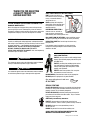
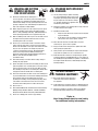
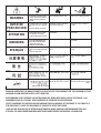
KEEP YOUR HEAD OUT OF THE FUMES.
DON’T get too close to the arc.
Use corrective lenses if necessary
to stay a reasonable distance
away from the arc.
READ and obey the Safety Data
Sheet (SDS) and the warning label
that appears on all containers of
welding materials.
USE ENOUGH VENTILATION or
exhaust at the arc, or both, to
keep the fumes and gases from
your breathing zone and the general area.
IN A LARGE ROOM OR OUTDOORS, natural ventilation may be
adequate if you keep your head out of the fumes (See below).
USE NATURAL DRAFTS or fans to keep the fumes away
from your face.
If you de velop unusual symptoms, see your supervisor.
Perhaps the welding atmosphere and ventilation system
should be checked.
WEAR CORRECT EYE, EAR &
BODY PROTECTION
PROTECT your eyes and face with welding helmet
properly fitted and with proper grade of filter plate
(See ANSI Z49.1).
PROTECT your body from welding spatter and arc
flash with protective clothing including woolen
clothing, flame-proof apron and gloves, leather
leggings, and high boots.
PROTECT others from splatter, flash, and glare
with protective screens or barriers.
IN SOME AREAS, protection from noise may be appropriate.
BE SURE protective equipment is in good condition.
Also, wear safety glasses in work area
AT ALL TIMES.
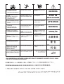
SPECIAL SITUATIONS
DO NOT WELD OR CUT containers or materials which previously
had been in contact with hazardous substances unless they are
properly cleaned. This is extremely dangerous.
DO NOT WELD OR CUT painted or plated parts unless special
precautions with ventilation have been taken. They can release
highly toxic fumes or gases.
Additional precautionary measures
PROTECT compressed gas cylinders from excessive heat,
mechanical shocks, and arcs; fasten cylinders so they cannot fall.
BE SURE cylinders are never grounded or part of an
electrical circuit.
REMOVE all potential fire hazards from welding area.
ALWAYS HAVE FIRE FIGHTING EQUIPMENT READY FOR
IMMEDIATE USE AND KNOW HOW TO USE IT.
WARNING
CAUTION
Safety 01 of 04 - 5/16/2018

SECTION A:
WARNINGS
CALIFORNIA PROPOSITION 65 WARNINGS
WARNING: Breathing diesel engine exhaust
exposes you to chemicals known to the State
of California to cause cancer and birth defects,
or other reproductive harm.
• Always start and operate the engine in a
well-ventilated area.
• If in an exposed area, vent the exhaust to the outside.
• Do not modify or tamper with the exhaust system.
• Do not idle the engine except as necessary.
For more information go to
www.P65 warnings.ca.gov/diesel
WARNING: This product, when used for welding or
cutting, produces fumes or gases which contain
chemicals known to the State of California to cause
birth defects and, in some cases, cancer. (California
Health & Safety Code § 25249.5 et seq.)
WARNING: Cancer and Reproductive Harm
www.P65warnings.ca.gov
ARC WELDING CAN BE HAZARDOUS. PROTECT
YOURSELF AND OTHERS FROM POSSIBLE SERIOUS
INJURY OR DEATH. KEEP CHILDREN AWAY.
PACEMAKER WEARERS SHOULD CONSULT WITH
THEIR DOCTOR BEFORE OPERATING.
Read and understand the following safety highlights. For
additional safety information, it is strongly recommended
that you purchase a copy of “Safety in Welding & Cutting -
ANSI Standard Z49.1” from the American Welding Society,
P.O. Box 351040, Miami, Florida 33135 or CSA Standard
W117.2-1974. A Free copy of “Arc Welding Safety” booklet
E205 is available from the Lincoln Electric Company,
22801 St. Clair Avenue, Cleveland, Ohio 44117-1199.
BE SURE THAT ALL INSTALLATION, OPERATION,
MAINTENANCE AND REPAIR PROCEDURES ARE
PERFORMED ONLY BY QUALIFIED INDIVIDUALS.
FOR ENGINE POWERED
EQUIPMENT.
1.a. Turn the engine off before troubleshooting
and maintenance work unless the
maintenance work requires it to be running.
1.b. Operate engines in open, well-ventilated areas or vent the engine
exhaust fumes outdoors.
1.c. Do not add the fuel near an open flame welding
arc or when the engine is running. Stop the
engine and allow it to cool before refueling to
prevent spilled fuel from vaporizing on contact
with hot engine parts and igniting. Do not spill fuel when filling
tank. If fuel is spilled, wipe it up and do not start engine until
fumes have been eliminated.
1.d. Keep all equipment safety guards, covers
and devices in position and in good repair.
Keep hands, hair, clothing and tools away
from V-belts, gears, fans and all other
moving parts when starting, operating or
repairing equipment.
1.e. In some cases it may be necessary to remove safety guards to
perform required maintenance. Remove guards only when
necessary and replace them when the maintenance requiring
their removal is complete. Always use the greatest care when
working near moving parts.
1.f. Do not put your hands near the engine fan. Do not attempt to
override the governor or idler by pushing on the throttle control
rods while the engine is running.
1.g. To prevent accidentally starting gasoline engines while turning
the engine or welding generator during maintenance work,
disconnect the spark plug wires, distributor cap or magneto wire
as appropriate.
1.h. To avoid scalding, do not remove the radiator
pressure cap when the engine is
hot.
ELECTRIC AND
MAGNETIC FIELDS MAY
BE DANGEROUS
2.a. Electric current flowing through any conductor
causes localized Electric and Magnetic Fields (EMF).
Welding current creates EMF fields around welding cables
and welding machines
2.b. EMF fields may interfere with some pacemakers, and
welders having a pacemaker should consult their physician
before welding.
2.c. Exposure to EMF fields in welding may have other health effects
which are now not known.
2.d. All welders should use the following procedures in order to
minimize exposure to EMF fields from the welding circuit:
2.d.1. Route the electrode and work cables together - Secure
them with tape when possible.
2.d.2. Never coil the electrode lead around your body.
2.d.3. Do not place your body between the electrode and work
cables. If the electrode cable is on your right side, the
work cable should also be on your right side.
2.d.4. Connect the work cable to the workpiece as close as pos-
sible to the area being welded.
2.d.5. Do not work next to welding power source.
SAFETY
Safety 02 of 04 - 5/16/2018

ELECTRIC SHOCK
CAN KILL.
3.a. The electrode and work (or ground) circuits are
electrically “hot” when the welder is on. Do
not touch these “hot” parts with your bare skin or wet clothing.
Wear dry, hole-free gloves to insulate hands.
3.b. Insulate yourself from work and ground using dry insulation.
Make certain the insulation is large enough to cover your full area
of physical contact with work and ground.
In addition to the normal safety precautions, if
welding must be performed under electrically
hazardous conditions (in damp locations or while
wearing wet clothing; on metal structures such as
floors, gratings or scaffolds; when in cramped
positions such as sitting, kneeling or lying, if there
is a high risk of unavoidable or accidental contact
with the workpiece or ground) use the following
equipment:
• Semiautomatic DC Constant Voltage (Wire) Welder.
• DC Manual (Stick) Welder.
• AC Welder with Reduced Voltage Control.
3.c. In semiautomatic or automatic wire welding, the electrode,
electrode reel, welding head, nozzle or semiautomatic welding
gun are also electrically “hot”.
3.d. Always be sure the work cable makes a good electrical
connection with the metal being welded. The connection should
be as close as possible to the area being welded.
3.e. Ground the work or metal to be welded to a good electrical (earth)
ground.
3.f. Maintain the electrode holder, work clamp, welding cable and
welding machine in good, safe operating condition. Replace
damaged insulation.
3.g. Never dip the electrode in water for cooling.
3.h. Never simultaneously touch electrically “hot” parts of electrode
holders connected to two welders because voltage
between the
two can be the total of the open circuit voltage of both
welders.
3.i. When working above floor level, use a safety belt to protect
yourself from a fall should you get a shock.
3.j. Also see It ems 6.c. and 8.
ARC RAYS CAN BURN.
4.a. Use a shield with the proper filter and cover plates to protect your
eyes from sparks and the rays of the arc when welding or
observing open arc welding. Headshield and filter lens should
conform to ANSI Z87. I standards.
4.b. Use suitable clothing made from durable flame-resistant material
to protect your skin and that of your helpers from the arc rays.
4.c. Protect other nearby personnel with suitable, non-flammable
screening and/or warn them not to watch the arc nor expose
themselves to the arc rays or to hot spatter or metal.
FUMES AND GASES
CAN BE DANGEROUS.
5.a. Welding may produce fumes and gases
hazardous to health. Avoid breathing these
fumes and gases. When welding, keep your head out of the fume.
Use enough ventilation and/or exhaust at the arc to keep fumes
and gases away from the breathing zone. When welding
hardfacing (see instructions on container or SDS)
or on lead or cadmium plated steel and other
metals or coatings which produce highly toxic
fumes, keep exposure as low as possible and
within applicable OSHA PEL and ACGIH TLV limits
using local exhaust or mechanical ventilation
unless exposure assessments indicate otherwise.
In confined spaces or in some circumstances,
outdoors, a respirator may also be required.
Additional precautions are also required when
welding
on galvanized steel.
5. b. The operation of welding fume control equipment is affected by
various factors including proper use and positioning of the
equipment, maintenance of the equipment and the specific
welding procedure and application involved. Worker exposure
level should be checked upon installation and periodically
thereafter to be certain it is within applicable OSHA PEL and
ACGIH TLV limits.
5.c. Do not weld in locations near chlorinated hydrocarbon vapors
coming from degreasing, cleaning or spraying operations. The
heat and rays of the arc can react with solvent vapors to form
phosgene, a highly toxic gas, and other irritating products.
5.d. Shielding gases used for arc welding can displace air and
cause
injury or death. Always use enough ventilation, especially in
confined areas, to insure breathing air is safe.
5.e. Read and understand the manufacturer’s instructions for this
equipment and the consumables to be used, including the
Safety Data Sheet (SDS) and follow your employer’s safety
practices. SDS forms are available from your welding
distributor or from the manufacturer.
5.f. Also see item 1.b.
SAFETY
Safety 03 of 04 - 5/16/2018

WELDING AND CUTTING
SPARKS CAN CAUSE
FIRE OR EXPLOSION.
6.a. Remove fire hazards from the welding area. If
this is not possible, cover them to prevent the welding sparks
from starting a fire. Remember that welding sparks and hot
materials from welding can easily go through small cracks and
openings to adjacent areas. Avoid welding near hydraulic lines.
Have a fire extinguisher readily available.
6.b. Where compressed gases are to be used at the job site, special
precautions should be used to prevent hazardous situations.
Refer to “Safety in Welding and Cutting” (ANSI Standard Z49.1)
and the operating information for the equipment being used.
6.c. When not welding, make certain no part of the electrode circuit is
touching the work or ground. Accidental contact can cause
overheating and create a fire hazard.
6.d. Do not heat, cut or weld tanks, drums or containers until the
proper steps have been taken to insure that such procedures
will not cause flammable or toxic vapors from substances inside.
They can cause an explosion even though they have been
“cleaned”. For information, purchase “Recommended Safe
Practices for the Preparation for Welding and Cutting of
Containers and Piping That Have Held Hazardous Substances”,
AWS F4.1 from the American Welding Society
(see address above).
6.e. Vent hollow castings or containers before heating, cutting or
welding. They may explode.
6.f. Sparks and spatter are thrown from the welding arc. Wear oil free
protective garments such as leather gloves, heavy shirt, cuffless
trousers, high shoes and a cap over your hair. Wear ear plugs
when welding out of position or in confined places. Always wear
safety glasses with side shields when in a welding area.
6.g. Connect the work cable to the work as close to the welding area
as practical. Work cables connected to the building framework or
other locations away from the welding area increase the
possibility of the welding current passing through lifting chains,
crane cables or other alternate circuits. This can create fire
hazards or overheat lifting chains or cables until they fail.
6.h. Also see item 1.c.
6.I. Read and follow NFPA 51B “Standard for Fire Prevention During
Welding, Cutting and Other Hot Work”, available from NFPA, 1
Batterymarch Park, PO box 9101, Quincy, MA 022690-9101.
6.j. Do not use a welding power source for pipe thawing.
CYLINDER MAY EXPLODE IF
DAMAGED.
7.a. Use only compressed gas cylinders containing
the correct shielding gas for the process used
and properly operating regulators designed for
the gas and pressure used. All hoses, fittings,
etc. should be suitable for the application and
maintained in good condition.
7.b. Always keep cylinders in an upright position securely chained to
an undercarriage or fixed support.
7.c. Cylinders should be located:
• Away from areas where they may be struck or subjected
to physical damage.
• A safe distance from arc welding or cutting operations
and any other source of heat, sparks, or flame.
7.d. Never allow the electrode, electrode holder or any other
electrically “hot” parts to touch a cylinder.
7.e. Keep your head and face away from the cylinder valve outlet
when opening the cylinder valve.
7.f. Valve protection caps should always be in place and hand tight
except when the cylinder is in use or connected for use.
7.g. Read and follow the instructions on compressed gas cylinders,
associated equipment, and CGA publication P-l, “Precautions for
Safe Handling of Compressed Gases in Cylinders,” available from
the Compressed Gas Association, 14501 George Carter Way
Chantilly, VA 20151.
FOR ELECTRICALLY
POWERED EQUIPMENT.
8.a. Turn off input power using the disconnect
switch at the fuse box before working on
the equipment.
8.b. Install equipment in accordance with the U.S. National Electrical
Code, all local codes and the manufacturer’s recommendations.
8.c. Ground the equipment in accordance with the U.S. National
Electrical Code and the manufacturer’s recommendations.
Refer to
http://www.lincolnelectric.com/safety
for additional safety information.
SAFETY
Safety 04 of 04 - 5/16/2018

iv
SAFETY
iv
PRÉCAUTIONS DE SÛRETÉ
Pour votre propre protection lire et observer toutes les instruc-
tions et les précautions de sûreté specifiques qui parraissent
dans ce manuel aussi bien que les précautions de sûreté
générales suivantes:
Sûreté Pour Soudage A L’Arc
1. Protegez-vous contre la secousse électrique:
a. Les circuits à l’électrode et à la piéce sont sous tension
quand la machine à souder est en marche. Eviter toujours
tout contact entre les parties sous tension et la peau nue
ou les vétements mouillés. Porter des gants secs et sans
trous pour isoler les mains.
b. Faire trés attention de bien s’isoler de la masse quand on
soude dans des endroits humides, ou sur un plancher
metallique ou des grilles metalliques, principalement dans
les positions assis ou couché pour lesquelles une
grande partie du corps peut être en contact avec la
masse.
c. Maintenir le porte-électrode, la pince de masse, le câble
de soudage et la machine à souder en bon et sûr état
defonctionnement.
d.Ne jamais plonger le porte-électrode dans l’eau pour le
refroidir.
e. Ne jamais toucher simultanément les parties sous tension
des porte-électrodes connectés à deux machines à soud-
er parce que la tension entre les deux pinces peut être le
total de la tension à vide des deux machines.
f. Si on utilise la machine à souder comme une source de
courant pour soudage semi-automatique, ces precautions
pour le porte-électrode s’applicuent aussi au pistolet de
soudage.
2. Dans le cas de travail au dessus du niveau du sol, se pro-
téger contre les chutes dans le cas ou on recoit un choc. Ne
jamais enrouler le câble-électrode autour de n’importe quelle
partie du corps.
3. Un coup d’arc peut être plus sévère qu’un coup de soliel,
donc:
a. Utiliser un bon masque avec un verre filtrant approprié
ainsi qu’un verre blanc afin de se protéger les yeux du
rayonnement de l’arc et des projections quand on soude
ou quand on regarde l’arc.
b. Porter des vêtements convenables afin de protéger la
peau de soudeur et des aides contre le rayonnement de
l‘arc.
c. Protéger l’autre personnel travaillant à proximité au
soudage à l’aide d’écrans appropriés et non-inflamma-
bles.
4. Des gouttes de laitier en fusion sont émises de l’arc de
soudage. Se protéger avec des vêtements de protection
libres de l’huile, tels que les gants en cuir, chemise épaisse,
pantalons sans revers, et chaussures montantes.
5. Toujours porter des lunettes de sécurité dans la zone de
soudage. Utiliser des lunettes avec écrans lateraux dans les
zones où l’on pique le laitier.
6. Eloigner les matériaux inflammables ou les recouvrir afin de
prévenir tout risque d’incendie dû aux étincelles.
7. Quand on ne soude pas, poser la pince à une endroit isolé de
la masse. Un court-circuit accidental peut provoquer un
échauffement et un risque d’incendie.
8. S’assurer que la masse est connectée le plus prés possible
de la zone de travail qu’il est pratique de le faire. Si on place
la masse sur la charpente de la construction ou d’autres
endroits éloignés de la zone de travail, on augmente le risque
de voir passer le courant de soudage par les chaines de lev-
age, câbles de grue, ou autres circuits. Cela peut provoquer
des risques d’incendie ou d’echauffement des chaines et des
câbles jusqu’à ce qu’ils se rompent.
9. Assurer une ventilation suffisante dans la zone de soudage.
Ceci est particuliérement important pour le soudage de tôles
galvanisées plombées, ou cadmiées ou tout autre métal qui
produit des fumeés toxiques.
10. Ne pas souder en présence de vapeurs de chlore provenant
d’opérations de dégraissage, nettoyage ou pistolage. La
chaleur ou les rayons de l’arc peuvent réagir avec les
vapeurs du solvant pour produire du phosgéne (gas forte-
ment toxique) ou autres produits irritants.
11. Pour obtenir de plus amples renseignements sur la sûreté,
voir le code “Code for safety in welding and cutting” CSA
Standard W 117.2-1974.
PRÉCAUTIONS DE SÛRETÉ POUR
LES MACHINES À SOUDER À
TRANSFORMATEUR ET À
REDRESSEUR
1. Relier à la terre le chassis du poste conformement au code
de l’électricité et aux recommendations du fabricant. Le dis-
positif de montage ou la piece à souder doit être branché à
une bonne mise à la terre.
2. Autant que possible, I’installation et l’entretien du poste
seront effectués par un électricien qualifié.
3. Avant de faires des travaux à l’interieur de poste, la
debrancher à l’interrupteur à la boite de fusibles.
4. Garder tous les couvercles et dispositifs de sûreté à leur
place.
Mar. ‘93

v
SAFETY
v
Electromagnetic Compatibility (EMC)
Conformance
Products displaying the CE mark are in conformity with European Community Council Directive of 3 May
1989 on the approximation of the laws of the Member States relating to electromagnetic compatibility
(89/336/EEC). It was manufactured in conformity with a national standard that implements a harmonized
standard: EN 60974-10 Electromagnetic Compatibility (EMC) Product Standard for Arc Welding Equipment.
It is for use with other Lincoln Electric equipment. It is designed for industrial and professional use.
Introduction
All electrical equipment generates small amounts of electromagnetic emission. Electrical emission may be
transmitted through power lines or radiated through space, similar to a radio transmitter. When emissions
are received by other equipment, electrical interference may result. Electrical emissions may affect many
kinds of electrical equipment; other nearby welding equipment, radio and TV reception, numerical controlled
machines, telephone systems, computers, etc. Be aware that interference may result and extra precautions
may be required when a welding power source is used in a domestic establishment.
Installation and Use
The user is responsible for installing and using the welding equipment according to the manufacturer’s
instructions. If electromagnetic disturbances are detected then it shall be the responsibility of the user of the
welding equipment to resolve the situation with the technical assistance of the manufacturer. In some cases
this remedial action may be as simple as earthing (grounding) the welding circuit, see Note. In other cases it
could involve construction of an electromagnetic screen enclosing the power source and the work complete
with associated input filters. In all cases electromagnetic disturbances must be reduced to the point where
they are no longer troublesome.
Note: The welding circuit may or may not be earthed for safety reasons according to national codes.
Changing the earthing arrangements should only be authorized by a person who is compe-
tent to access whether the changes will increase the risk of injury, e.g., by allowing parallel
welding current return paths which may damage the earth circuits of other equipment.
Assessment of Area
Before installing welding equipment the user shall make an assessment of potential electromagnetic prob-
lems in the surrounding area. The following shall be taken into account:
a) other supply cables, control cables, signaling and telephone cables; above, below and adjacent to the
welding equipment;
b) radio and television transmitters and receivers;
c) computer and other control equipment;
d) safety critical equipment, e.g., guarding of industrial equipment;
e) the health of the people around, e.g., the use of pacemakers and hearing aids;
f) equipment used for calibration or measurement
g) the immunity of other equipment in the environment. The user shall ensure that other equipment being
used in the environment is compatible. This may require additional protection measures;
h) the time of day that welding or other activities are to be carried out.
L10093 3-1-96H

SAFETY
vi
vi
Electromagnetic Compatibility (EMC)
The size of the surrounding area to be considered will depend on the structure of the building and other
activities that are taking place. The surrounding area may extend beyond the boundaries of the premises.
Methods of Reducing Emissions
Mains Supply
Welding equipment should be connected to the mains supply according to the manufacturer’s recommenda-
tions. If interference occurs, it may be necessary to take additional precautions such as filtering of the mains
supply. Consideration should be given to shielding the supply cable of permanently installed welding equip-
ment, in metallic conduit or equivalent. Shielding should be electrically continuous throughout its length. The
shielding should be connected to the welding power source so that good electrical contact is maintained
between the conduit and the welding power source enclosure.
Maintenance of the Welding Equipment
The welding equipment should be routinely maintained according to the manufacturer’s recommendations.
All access and service doors and covers should be closed and properly fastened when the welding equip-
ment is in operation. The welding equipment should not be modified in any way except for those changes
and adjustments covered in the manufacturers instructions. In particular, the spark gaps of arc striking and
stabilizing devices should be adjusted and maintained according to the manufacturer’s recommendations.
Welding Cables
The welding cables should be kept as short as possible and should be positioned close together, running at
or close to floor level.
Equipotential Bonding
Bonding of all metallic components in the welding installation and adjacent to it should be considered.
However, metallic components bonded to the work piece will increase the risk that the operator could
receive a shock by touching these metallic components and the electrode at the same time. The operator
should be insulated from all such bonded metallic components.
Earthing of the Workpiece
Where the workpiece is not bonded to earth for electrical safety, not connected to earth because of its size
and position, e.g., ships hull or building steelwork, a connection bonding the workpiece to earth may reduce
emissions in some, but not all instances. Care should be taken to prevent the earthing of the workpiece
increasing the risk of injury to users, or damage to other electrical equipment. Where necessary, the connec-
tion of the workpiece to earth should be made by a direct connection to the workpiece, but in some countries
where direct connection is not permitted, the bonding should be achieved by suitable capacitance, selected
according to national regulations.
Screening and Shielding
Selective screening and shielding of other cables and equipment in the surrounding area may alleviate prob-
lems of interference. Screening of the entire welding installation may be considered for special applications.
1
_________________________
1
Portions of the preceding text are contained in EN 60974-10: “Electromagnetic Compatibility (EMC) prod-
uct standard for arc welding equipment.”
L10093 3-1-96H

viii viii
Page
Installation.......................................................................................................Section A
Technical Specifications........................................................................................A-1
Safety Precautions.................................................................................................A-2
Select Suitable Location........................................................................................A-2
Electromagnetic Compatibility (EMC) .............................................................A-2
Stacking ..........................................................................................................A-2
Tilting...............................................................................................................A-2
Input Connections..................................................................................................A-2
Fuses and Wire Sizes.....................................................................................A-2
Ground Connection.........................................................................................A-2
Input Power Supply Connections....................................................................A-3
Reconnect Procedure............................................................................................A-3
Output Connections...............................................................................................A-4
Auxiliary Power and Control Connections......................................................A-5, A-6
________________________________________________________________________
Operation.........................................................................................................Section B
Safety Precautions ................................................................................................B-1
General Description, Recommended Processes and Equipment..........................B-1
Design Features ....................................................................................................B-1
Welding Capabillity................................................................................................B-2
Graphic Symbols ...................................................................................................B-2
Controls and Settings .............................................................................B-3 Thru B-5
Case Back Connections ........................................................................................B-5
Auxiliary Power......................................................................................................B-5
Machine Protection.................................................................................B-5 Thru B-6
Welding Performance.............................................................................B-6 Thru B-7
________________________________________________________________________
Accessories.....................................................................................................Section C
Power Wire Feeders..............................................................................................C-1
Field Installed Options...........................................................................................C-1
Remote Output Control..........................................................................................C-1
________________________________________________________________________
Maintenance ....................................................................................................Section D
Safety Precautions ................................................................................................D-1
General Maintenance............................................................................................D-1
________________________________________________________________________
Troubleshooting ..............................................................................................Section E
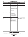
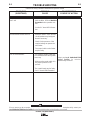
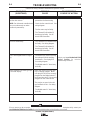
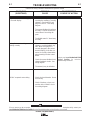
How to Use Troubleshooting Guide.......................................................................E-1
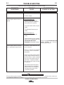
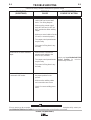
Troubleshooting Guide ...........................................................................E-2 Thru E-7
P.C. Board Troubleshooting Guide................................................................E-8, B-9
________________________________________________________________________
Connection, Wiring Diagrams and Dimension Prints ..................................Section F
________________________________________________________________________
Parts List .....................................................................................................P-587 Series
________________________________________________________________________
TABLE OF CONTENTS

A-1
DC655e (CE) (RED-D-ARC)
A-1
INSTALLATION
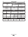
TECHNICAL SPECIFICATIONS – DC655e (CE)
Volts at Rated Amperes
44
44
Auxiliary Power
See the OPERATION section for
Auxiliary Power information
Amps
650
815
Maximum Open Circuit Voltage
46 CV Mode
68 CC Mode
Duty Cycle
100% Duty Cycle
IEC974-1
60% Duty Cycle
INPUT - THREE PHASE ONLY
OUTPUT
1
Also called “inverse time” or “thermal/magnetic” circuit breakers; circuit breakers which have a delay in tripping action that decreases as the magnitude of the current increases.
RECOMMENDED INPUT WIRE AND FUSE SIZES
Standard
Voltage
230/400/50/60*
100% Duty Cycle
122/70
60% Duty Cycle
150/86
Input Current at Rated Output
RATED OUTPUT
INPUT
VOLTAGE /
FREQUENCY
230
400
(SUPER LAG)
OR BREAKER
SIZE (AMPS)
1
225 Amp
125 Amp
Copper
GROUND WIRE
IN CONDUIT
AWG(IEC-MM
2
) SIZES
4 (21)
6 (14)
TYPE 80°C
COPPER WIRE
IN CONDUIT
AWG(IEC-MM
2
) SIZES
40°C (104°F) Ambient
1 (43)
4 (21)
INPUT AMPERE
RATING ON
NAMEPLATE
122
70
HERTZ
50/60
50/60
PHYSICAL DIMENSIONS
HEIGHT
27.5 in
699 mm
WIDTH
22.2 in
564 mm
DEPTH
38.0 in
965 mm
WEIGHT
720 lbs.
326 kg.
Current Range
50-815
Voltage Range
13-44 DC

A-2
INSTALLATION
DC655e (CE) (RED-D-ARC)
A-2
Read entire installation section before starting
installation.
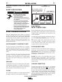
SAFETY PRECAUTIONS
SELECT SUITABLE LOCATION
Place the welder where clean cooling air can freely
circulate in through the front louvers and out through
the rear louvers. Dirt, dust or any foreign material that
can be drawn into the welder should be kept at a
minimum. Failure to observe these precautions can
result in excessive operating temperatures and
nuisance shut-downs.
ELECTROMAGNETIC COMPATIBILITY (EMC)
The EMC classification of the
DC655e (CE)
is Industrial,
Scientific and Medical (ISM) group 2, class A. The
DC655e
(CE)
is for industrial use only. (See prints L10093-1, -2
Safety Pages in the front of Instruction Manual for further
details).
Locate the
DC655e (CE)
away from radio controlled
machinery. The normal operation of the
DC655e (CE)
may adversely affect the operation of RF controlled equip-
ment, which may result in bodily injury or damage to the
equipment.
STACKING
The DC655e (CE) may be stacked three-high provid-
ed the bottom machine is on a stable, hard, level sur-
face. Be sure that the two pins in the roof fit into the
slots in the base of the DC655e (CE) above it.
TILTING
Do not place the machine on a surface that is inclined
enough to create a risk of the machine falling over.
ELECTRICAL
INPUT CONNECTIONS
Before installing the machine check that the input sup-
ply voltage, phase, and frequency are the same as the
voltage, phase, and frequency as specified on the
welder nameplate.
Use input wire sizes that meet local electrical codes or
see the Technical Specifications page in this manu-
al.
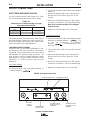
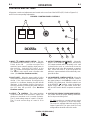
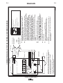
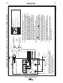
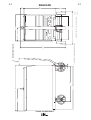
Input power supply entry is through the hole in the
Case Back Assembly. See Figure A.1 for the location
of the machine’s input cable entry opening, Input
Contactor (CR1), and reconnect panel.
FUSE AND WIRE SIZES
Protect the input circuit with the super lag fuses or
delay type circuit breakers listed on the Technical
Specifications page of this manual for the machine
being used. They are also called inverse time or ther-
mal/magnetic circuit breakers.
DO NOT use fuses or circuit breakers with a lower
amp rating than recommended. This can result in
“nuisance” tripping caused by inrush current even
when machine is not being used for welding at high
output currents.
GROUND CONNECTION
Ground the frame of the machine. A ground
terminal marked with the symbol ( ) is located inside
the case back of the machine near the input contactor.
Access to the input box assembly is at the upper rear
of the machine. See your local and national electrical
codes for proper grounding methods. Use grounding
wire sizes that meet local electrical codes or see the
Technical Specifications page in this manual.
ELECTRIC SHOCK can kill.
• Only qualified personnel should
perform this installation.
• Turn the input power OFF at the discon-
nect switch or fuse box before working on
this equipment.
• Turn the Power switch on the DC655e
(CE) “OFF” before connecting or discon-
necting output cables, wire feeder or
remote connections, or other equipment.
• Do not touch electrically hot parts.
• Always connect the DC655e (CE) ground-
ing terminal (located on the welder near
the reconnect panel) to a good
electrical earth ground.
WARNING
INPUT POWER SUPPLY
C
ABLE WITH BUSHING
OR BOX CONNECTOR
INPUT
CONTACTOR (CR1)
R
ECONNECT
P
ANEL ASSEMBLY
FIGURE A.1 ELECTRICAL INPUT CONNECTIONS

A-3
INSTALLATION
DC655e (CE) (RED-D-ARC)
A-3
INPUT POWER SUPPLY CONNECTIONS
A qualified electrician should connect the input power
supply leads.
1. Follow all national and local electrical codes.
2. Use a three-phase line.
3. Remove the input access door at upper rear of the
machine.
4. Follow input supply connection diagram located
on the inside the door. For multiple voltage
machines, follow the diagram for the voltage that
is within 10% of your actual input line voltage.
5. Connect the three-phase AC power supply leads
L1, L2, and L3 to the input contactor
terminals in the input box assembly. See Figure
A.1.
RECONNECT PROCEDURE
Electric Shock Can Kill
• Disconnect input power before per-
forming this procedure.
------------------------------------------------------------------------
Multiple voltage machines are shipped connected to
the highest input voltage listed on the machine’s rating
plate. Before installing the machine, check that the
reconnect panel in the input box assembly is connect-
ed for the proper voltage.
Failure to follow these instructions can cause
immediate failure of components within the
machine. When powering welder from a generator
be sure to turn off welder first, before generator is
shut down in order to prevent damage to welder.
------------------------------------------------------------------------
To reconnect a multiple voltage machine to a different
voltage, remove input power and refer to the input
connection diagram located on the inside of case back
input access door. Follow the diagram for the voltage
that is within 10% of your actual input line voltage.
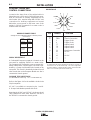
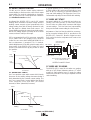
1. Figure A.2 shows a sample of the reconnect
instructions for a dual voltage machine.
CAUTION
WARNING
FIGURE A.2 Dual Voltage Machine Reconnection Procedure

A-4
INSTALLATION
DC655e (CE) (RED-D-ARC)
A-4
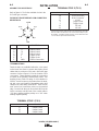
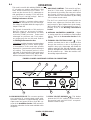
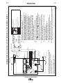
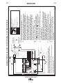
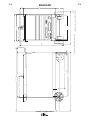
OUTPUT CONNECTIONS
ELECTRODE AND WORK CABLES
Use the shortest possible cable lengths. See Table
A.1 for recommended cable sizes based on length.
The output terminals are located at the lower front of
the welder behind a hinged door Refer to figure A.3.
Route the welding cables through the slotted strain
reliefs of the base to the welding terminals.
LOW INDUCTANCE TERMINAL
On the DC655e (CE), the inside right Negative (-) out-
put terminal is lower choke inductance. This terminal
is presently only recommended for CV mode welding
with NR203Ni 1% negative polarity procedures. All
other processes are to be welded using the outside
right Negative (-) output terminal with higher choke
inductance. CC mode processes must use high
inductance.
For Positive Polarity:
1. Connect the work cable to the high inductance (-)
terminal (marked " ").
2. Connect the electrode cable to the positive terminal
marked “+”.
3. Remove the terminal strip access cover panel on
the lower case front. Refer to figure A.3 for the
location.
4. Work Sense lead #21 from the 14 Pin MS-recepta-
cle must be connected to “-21”on the terminal strip.
Note: This is how the DC655e (CE) is shipped
from the factory.
5. Replace the terminal strip access cover panel.
For Negative Polarity:
1. Connect the electrode cable to the appropriate high
inductance (-) terminal (marked " ") or
to the low inductance (-) terminal
(marked " ") if using NR203Ni 1% elec-
trode only.
2. Connect the work cable to the positive terminal
marked “+”.
3. Remove the terminal strip access cover panel on
the lower case front. Refer to figure A.3 for the
location.
4. Work Sense lead #21 from the 14 Pin MS-recepta-
cle must be connected to “+21”on the terminal strip.
5. Replace the terminal strip access cover panel.
TABLE A.1
Cable Sizes for Combined Lengths of Copper
Electrode and Work Cable
Cable Length
ft. (m)
Parallel Cables Cable Size
0 (0) to 100 (30.4)
100 (30.4) to 200 (60.8)
200 (60.8) to 250 (76.2)
2
2
2
2/0 ( 70mm
2
)
3/0 ( 95mm
2
)
4/0 (120mm
2
)
POSITIVE
OUTPUT
TERMINAL
LOW INDUCTANCE
NEGATIVE OUTPUT
TERMINAL
HIGH INDUCTANCE
NEGATIVE OUTPUT
TERMINAL
TERMINAL STRIP
COVER PANEL
14 PIN MS RECEPTACLE
6 PIN MS RECEPTACLE
FIGURE A.3 Output Connections

A-5
INSTALLATION
DC655e (CE) (RED-D-ARC)
A-5
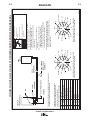
FIGURE A.4 FRONT VIEW OF 14-PIN CONNECTOR
RECEPTACLE
PIN LEAD NO. FUNCTION
A --- ---
B GND Chassis Connection
C2 Trigger Circuit
D4 Trigger Circuit
E 77 Output Control
F 76 Output Control
G 75 Output Control
H 21 Work Sense Connection
1
I 41 42 VAC
J --- ---
K 42 42 VAC
L --- ---
M --- ---
N --- ---
F=76
G=75
H=21
I
=41
J
K
=42
A
B=GND
C=2
D
=4
E=77
L
N
M
1
As shipped from the factory Lead #21 from the 14 Pin connector is
connected to “-21” on the terminal strip. This is the configuration
for positive welding. If welding negative polarity, connect lead #21
to the “+21” connection point on the terminal strip.
AUXILIARY POWER AND
CONTROL CONNECTIONS
Located at the lower front of the welder behind a
hinged door are a 6-Pin and a 14-Pin MS type recep-
tacle for connection of auxiliary equipment such as
wire feeders. Also, terminal strips with 115VAC and
connections for auxiliary equipment are located
behind the access panel on the lower case of the
welder. A 220VAC receptacle for a water cooler is
located on the case back.
220VAC RECEPTACLE
A Continental European receptacle is located on the
rear panel for supplying 220VAC to a water cooler.
The receptacle has a protective cover to prevent inci-
dently contact and is a Schuko type. The circuit is pro-
tected by a 2 amp circuit breaker also located on the
rear panel. This circuit is electrically isolated from all
other circuits, but on the European Models one line is
connected to chassis ground.
AUXILIARY POWER TABLE
Voltage and Circuit Breaker Ratings at Auxiliary Power
Connections
Auxiliary Export
Power Models
Connections (50/60 Hz)
Terminal strip 115V 15A
terminals 31 & 32
14 pin MS-
Receptacle 42V 10A
pins I & K
At 220V 220V 2A
Receptacle
14-PIN MS TYPE RECEPTACLE
(For MS3106A-20-27PX Plug. L.E.C. Part #S12020-32)
Refer to the figure A.4 for the available circuits in the
14 pin receptacle.
42 VAC is available at receptacle pins I and K.
A 10 amp circuit breaker protects this circuit.
Note that the 42 VAC and 115 VAC circuits are electri-
cally isolated from each other. However, one line of
the 115VAC is connected to chassis ground.

A-6
INSTALLATION
DC655e (CE) (RED-D-ARC)
A-6
6-PIN MS TYPE RECEPTACLE
Refer to figure A.5 for for the available circuits in the
6 -Pin MS type connector.
TERMINAL STRIPS
Terminal strips are available behind the cover panel
on the lower case front to connect wire feeder control
cables that do not have a 6-Pin and a 14-Pin MS-type
connector. Refer to figure A.3 for the location of this
cover panel. These terminals supply the connections
as shown in the following Terminal Strip charts. See
Auxiliary Power Table for rating of circuit breaker in
115VAC circuit. Remove a plug button from the termi-
nal strip cover and install an appropriate strain relief
clamp for the cable being used. NOTE: There are two
work sense lead connection points on the terminal
strip. Connect both the work sense lead #21 from the
14-Pin connector and #21 lead of the control cable to
“-21” when welding positive polarity or to “+21” when
welding negative polarity.
TERMINAL STRIP 1 (T.S.1)
TERMINAL STRIP 2 (T.S.2)
Lead No. Function
75 Output Control
76 Output Control
77 Output Control
1
If connecting a feeder cable directly to the terminal strip, Lead #21
from the cable is connected to “-21” on the terminal strip for posi-
tive welding. If welding negative polarity, connect lead #21 to the
“+21” connection point on the terminal strip.
Lead No. Function
+21 Work Connection
-21 Work Connection
1
41 42 VAC
4 Trigger Circuit
2 Trigger Circuit
31 115 VAC
32 115 VAC
FIGURE A.5 FRONT VIEW OF 6-PIN CONNECTOR
RECEPTACLE
PIN LEAD NO. FUNCTION
A 77 Output Control
B 76 Output Control
C 75 Output Control
D2 Trigger Circuit
E4 Trigger Circuit
F GND Chassis Connection
D=2
E=4
F=GND
A
=77
B=76
C=75

B-1
OPERATION
B-1
GENERAL DESCRIPTION
The DC655e (CE) is an energy efficient constant voltage DC
power source that produces outstanding arc characteristics
for multiple CV or CC welding processes
This is a European 50/60 Hertz models that is “CE” qualified
and rated for IEC 974-1.
RECOMMENDED PROCESSES AND
EQUIPMENT
The DC655e (CE) is designed for CV or CC process-
es.
CV processes include: GMAW (MIG) and FCAW (flux-
cored) welding, plus the capability of CV submerged
arc welding and air carbon arc gouging. It produces
outstanding welding performance with a single range
full output control knob.
CC processes include stick welding, CC submerged
arc and superior air carbon arc gouging with up to 3/8”
(10 mm) diameter carbons. The same single range full
output control knob is used and paralleling capability
is provided.
The DC655e (CE) is recommended for use with
Lincoln’s DH-10 or LN-10 as well as the LN-7*, LN-7
GMA*,LN-15, LN-742, LN-8*, LN-9*, LN-9 GMA*, LN-
23P and LN-25 semiautomatic wire feeders. It is also
recommended for use with the NA-3, NA-5 and NA-5R
automatic feeders. “Cold starting” for sub-arc or
across arc “touch-sensing” can be used.
* The 14-pin MS receptacle does not provide 115 VAC
for these feeders; 115 VAC must be obtained from
terminal strip.
Two DC655e (CE) may be paralleled in a “master”
and “slave” interconnection using the K1611-1
Paralleling kit.
DESIGN FEATURES AND ADVANTAGES
• Separate output terminals for selecting high or low
inductance as recommended for the welding
process.
• Power on/off switch with pilot light and thermostat
tripped indicator light.
• Full range output voltage (CV mode) and current
(CC mode) control for easy operation.
DC655e (CE) (RED-D-ARC)
ELECTRIC SHOCK
can kill.
• Do not touch electrically live parts
or electrode with skin or wet
clothing.
• Insulate yourself from work and
ground.
• Always wear dry insulating
gloves.
------------------------------------------------------------------------
FUMES AND GASES
can be dangerous.
• Keep your head out of fumes.
• Use ventilation or exhaust to
remove fumes from breathing
zone.
------------------------------------------------------------------------
WELDING SPARKS
can cause fire or
explosion
• Keep flammable material away.
• Do not weld on containers that
have held combustibles.
------------------------------------------------------------------------
ARC RAYS
can burn.
• Wear eye, ear and body
protection.
------------------------------------------------------------------------
SAFETY PRECAUTIONS
Read and understand this entire section before oper-
ating the machine.
Observe additional Safety Guidelines detailed
throughout this manual.
WARNING

B-2
OPERATION
B-2
• Panel switches behind a latched front panel for
remote or local output control, output on or remote
selection, and CC, CV Sub-arc or CV MIG mode
selection.
• Panel knob settable CC arc force control with built-in
adjustable “Hot Start”.
• High efficiency output, and selectable “sleep mode”
idle mode timer which shuts down input power if not
used for extra energy conservation.
• Fan as needed (F.A.N.). Solid state thermally con-
trolled fan operates cooling fan only when required.
Minimizes power consumption, operating noise and
dust intake.
• Hinged cover to protect output terminals and auxil-
iary connections.
• Electronic and thermostatic protection for current
overload and excessive temperatures.
• 42 VAC, 10 amp auxiliary power available for the
wire feeder; circuit breaker protected.
• 115 VAC, auxiliary power protected by a 15 amp
breaker.
• 220 VAC receptacle for connecting to a water cooler.
Protected by 2 amp breaker.
• MS-type (6-pin) and (14-pin) connections for remote
and wire feeder.
• Optional Field Installed Digital or Analog
Voltmeter/Ammeter kits are available.
• Optional Dual Process Switch for two processes with
polarity change and electrical isolation.
WELDING CAPABILITY
The DC655e (CE) has the following Output and Duty
Cycle based on operation for a 10 minute period:
650 Amps, 44 Volts at 100%
815 Amps, 44 Volts at 60%
DC655e (CE) (RED-D-ARC)
GRAPHIC SYMBOLS THAT APPEAR ON
RATING PLATE (LOCATED ON CASE
BACK)
3 Phase transformer with
rectified DC output
INPUT POWER
THREE PHASE
GMAW
FCAW
Constant Voltage Output
Characteristics
Designates welder complies with
International Electrotechnical
Commission requirements 974-1.
IEC 974-1
Designates welder complies with
low voltage directive and with
EMC directive.
CE
Designates welder can be used
in environments with increased
hazard of electric shock.
S
SMAW
SAW
Constant Current Output
Characteristics
Designates the degree of envi-
ronmental protection provided by
the power sources enclosure.
IP-23
Open Circuit Output Voltage
U
o
Input Voltage Rating(s)
U
1
Input Current Rating(s)
I
1
Output Voltage Rating(s)
U
2
Output Duty Cycle Rating(s)
X
Output Current Rating(s)
I
2

B-3
OPERATION
B-3
1. INPUT POWER ON/OFF SWITCH - This tog-
gle switch turns the machine on or off. Putting the
switch in the ON position energizes the
machine’s input contactor applying input power to
the machine. Switching the switch to the
OFF position de-energizes the input contactor.
This switch is also used to reset a machine shut-
down. (See Machine Shutdown section)
2. PILOT LIGHT - When the power switch is in the
ON position the machine’s white pilot light will illu-
minate. If the input contactor de-energizes the
machine in a shutdown situation the pilot will still
illuminate. In this situation it will be necessary to
reset the machine by switching the power switch to
the OFF then ON position. (See Machine
Shutdown section)
3. OUTPUT CONTROL - This control provides
continuous control of the machine’s output from
minimum to maximum as it is rotated clockwise.
The CV mode voltage range of control is 13 to 44V.
The CC mode current range of control is 50 to
815A.
4. OUTPUT TERMINALS ON/REMOTE - When this
switch is in the REMOTE position, the DC655e
(CE) output terminals will be electrically “cold” until
a remote device such as a wire feeder closes the
#2 and #4 circuit in the MS-receptacle or terminal
strip. When this switch is in the ON position the
machine’s output terminals will be electrically ener-
gized all the time.
5. LOCAL/REMOTE CONTROL SWITCH - When this
switch is set to the LOCAL position, control of
the output voltage is via the output control on the
DC655e (CE) control panel. When this switch is set
to the REMOTE position, control is through a
remote source such as a wire feeder via the #75,
#76, and #77 leads in the MS-receptacle or terminal
strip.
6. CC STICK/CV SUBARC/CV MIG MODE SWITCH -
This switch selects the proper welding characteris-
tics for the process being used:
CC Stick
provides a constant current output
characteristic through the 50 to 815 amp range.
The current is adjusted within this range by the
Output Control dial. The open circuit (no load)
voltage will be about 68 volts in this mode.
DC655e (CE) (RED-D-ARC)
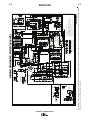
CONTROLS AND SETTINGS
All operator controls and adjustments are located on the case front of the DC655e (CE). Refer to Figures B.1,
and B.2 and corresponding explanations.
FIGURE B.1 CONTROL PANEL CONTROLS
DC655e
5
4
8
1
9
2
3
6
7

B-4
OPERATION
B-4
This mode is used for stick welding (SMAW) and
CC air carbon-arc gouging, and employs a “Hot
Start” feature and an Arc Force Control. CC
mode may also be used for CC submerged arc
with appropriate arc-sensing CC(VV) wire feed-
ers if arc force is set high enough. Refer to
Welding Performance Section.
CV MIG
provides a constant voltage output
characteristic through the 13 to 44 volt range.
The voltage is adjusted within this range by the
Output Control dial.
The dynamic characteristics of this mode are
ideal for open arc processes including,
MIG/MAG (GMAW), Innershield®, and other
cored wire (FCAW) processes. Faster travel
submerged arc processes and CV air carbon-
arc gouging may also use this mode. Refer to
the Welding Performance Section.
CV Sub-Arc
provides the same constant voltage
output control range as CV MIG, but the dynam-
ic characteristics of this mode make possible
improved CV (constant wire speed) submerged
arc welding. This improved process is most
noticeable on high deposition slow travel speed
welds. Fast travel, narrow bead subarc welds
will have better performance in CV MIG mode.
7. ARC FORCE CONTROL - This control is only func-
tional in CC Stick mode. It prevents “stubbing” of
the electrode by providing the extra weld current
that linearly increases as the welding voltage
decreases below a level determined by the setting
of the constant current control.
The Arc Force control knob, located behind the
latched cover, adjusts arc force from “Min” (no cur-
rent increase) to “Max” (higher short circuit current).
“Mid” position (#5) is recommended for most CC
welding. Refer to the Welding Performance
Section.
8. OPTIONAL VOLTMETER & AMMETER - Digital
or analog meter kits are available as field installed
options. Refer to the Accessories Section of this
manual.
9. THERMAL PROTECTION LIGHT - If the
machine overheats due to lack of proper air flow
through the machine or due to exceeding the
machine’s duty cycle, thermostats will disable the
welding output and this light will illuminate. Input
power is still applied to the machine and the cooling
fan will continue to run. When the machine cools
the welding output will resume.
DC655e (CE) (RED-D-ARC)
1. 6-PIN MS-RECEPTACLE-This connector provides
easy connection for a remote output control cable.
It provides connections for output switching, remote
output control and ground. Refer to 6-pin MS con-
nector in the Installation Section of this manual for
information about the circuits made avaliable at this
receptacle.
2. 115VAC CIRCUIT BREAKER - This breaker
protects the 115 VAC auxiliary circuits located in
the terminal strip and 14-Pin MS- receptacle.
Breaker is rated 15 amps.
FIGURE B.2 LOWER CASE FRONT CONTROLS & CONNECTIONS
7
6
5
4
3
1
2

B-5
OPERATION
B-5
DC655e (CE) (RED-D-ARC)
3. 42VAC 10 AMP CIRCUIT BREAKER - This
breaker protects the 42VAC auxiliary circuits locat-
ed in the terminal strip and MS-receptacle.
4. 14-PIN MS-RECEPTACLE - This connector pro-
vides easy connection for a wire feeder control
cable. It provides connections for auxiliary power,
output switching, remote output control, wire feeder
voltmeter sense lead and ground. Refer to 14-Pin
MS Type Receptacle in the Installation Section of
this manual for information about the circuits made
available at this receptacle.
5. TERMINAL STRIP COVER PANEL - Remove this
panel to gain access to the circuits made available
at the terminal strip and the 4-pin receptacle for the
optional paralleling kit. This terminal strip contains
the same circuits as the 14 pin MS-receptacle. The
cover also provides for installation of cable strain
relief clamps.
6. POSITIVE OUTPUT TERMINAL - This output ter-
minal is for connecting a welding cable. To change
welding polarity and for proper welding cable size
refer to Electrode and Work Cables in the
Installation Section of this manual.
7. NEGATIVE OUTPUT TERMINALS - These output
terminals are for connecting a welding cable to
either the High Inductance or Low Inductance
Terminal for desired arc characteristics. (Low induc-
tance is recommended only for NR203Ni 1%). To
change welding polarity and for proper welding
cable size refer to Electrode and Work Cables in
the Installation Section of this manual.
CASE BACK CONNECTIONS
220VAC AUXILIARY RECEPTACLE
This receptacle provides up to 2 amps of 220VAC
auxiliary power for a water cooler.
220VAC 2 AMP CIRCUIT BREAKER
This breaker protects the 220VAC auxiliary circuit
located in the 220VAC receptacle.
AUXILIARY POWER
42 volt AC auxiliary power, as required for some wire
feeders, is available through the wire feeder recepta-
cle. A 10 amp circuit breaker protects the 42 volt cir-
cuit from overloads.
Note that some types of equipment, especially
pumps and large motors, have starting currents
which are significantly higher than their running
current. These higher starting currents may cause
the circuit breaker to open. If this situation occurs,
the user should refrain from using the DC655e
(CE) auxiliary power for that equipment.
------------------------------------------------------------------------
MACHINE PROTECTION
THERMAL FAN CONTROL
The machine’s cooling fan remains off when the tem-
perature of the rectifiers and windings inside the
machine are below that requiring air flow cooling, as
determined by electronic monitoring of several thermal
sensors and the welding current of the machine. The
fan may remain off until welding begins, but once the
fan is activated, it will remain on for at least 5 minutes
to assure proper cooling. This feature saves energy
and also minimizes the amount of dirt and other air
borne particles being drawn into the machine.
FAN MOTOR FUSE
A 10 amp slow blow fuse protects the fan motor cir-
cuit. This fuse is located inside the DC655e (CE)
mounted on the fan motor bracket.
MACHINE SHUTDOWN
The DC655e (CE) provides shutdown modes for ther-
mal over-heating, excessive load currents and faults.
It also provides an idle timer shutdown feature for
additional operating economy.
CAUTION
La page charge ...
La page charge ...
La page charge ...
La page charge ...
La page charge ...
La page charge ...
La page charge ...
La page charge ...
La page charge ...
La page charge ...
La page charge ...
La page charge ...
La page charge ...
La page charge ...
La page charge ...
La page charge ...
La page charge ...
La page charge ...
La page charge ...
La page charge ...
La page charge ...
La page charge ...
La page charge ...
La page charge ...
La page charge ...
-
 1
1
-
 2
2
-
 3
3
-
 4
4
-
 5
5
-
 6
6
-
 7
7
-
 8
8
-
 9
9
-
 10
10
-
 11
11
-
 12
12
-
 13
13
-
 14
14
-
 15
15
-
 16
16
-
 17
17
-
 18
18
-
 19
19
-
 20
20
-
 21
21
-
 22
22
-
 23
23
-
 24
24
-
 25
25
-
 26
26
-
 27
27
-
 28
28
-
 29
29
-
 30
30
-
 31
31
-
 32
32
-
 33
33
-
 34
34
-
 35
35
-
 36
36
-
 37
37
-
 38
38
-
 39
39
-
 40
40
-
 41
41
-
 42
42
-
 43
43
-
 44
44
-
 45
45


Lincoln Electric Red-D-Arc DC655e Mode d'emploi
- Catégorie
- Système de soudage
- Taper
- Mode d'emploi
dans d''autres langues
Documents connexes
-
Lincoln Electric Red-D-Arc DX500e Mode d'emploi
-
-
-
-
-
-
Lincoln Electric LN-25 Pro Mode d'emploi
-
-
-
Lincoln Electric INVERTER ARC 120 Manuel utilisateur