Craftsman CMEW020 Manuel utilisateur
- Catégorie
- Outils électroportatifs
- Taper
- Manuel utilisateur

final page size: 8.5 x 5.5 in CRAFTSMAN
6" (152 mm) Variable Speed Bench Jointer
Banc de dégauchissage de 152 mm (6 po) à
vitesse variable
Ingleteadora de Banco de Velocidad Variable de
152 mm (6")
CMEW020
INSTRUCTION MANUAL | GUIDE D’UTILISATION | MANUAL DE INSTRUCTIONES
IF YOU HAVE QUESTIONS OR COMMENTS, CONTACT US.
POUR TOUTE QUESTION OU TOUT COMMENTAIRE, NOUS CONTACTER.
SI TIENE DUDAS O COMENTARIOS, CONTÁCTENOS.
1-888-331-4569 WWW.CRAFTSMAN.COM

English (original instructions) 1
Français (traduction de la notice d’instructions originale) 14
Español (traducido de las instrucciones originales) 28

1
ENGLISH
English (original instructions)
LangRef_U_NA_U_U-ENG
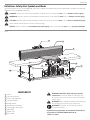
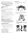
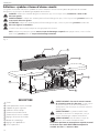
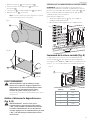
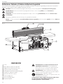
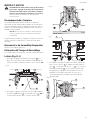
COMPONENTS
1 Fence
2 Cutterhead guard
3 Fence sliding bracket
4 Cutterhead lock
5 On/off switch
6 Variable speed control
7 Table height adjustment
8 Lock knob
9 Depth scale
10 Dust shoot
Definitions: Safety Alert Symbols and Words
This instruction manual uses the following safety alert symbols and words to alert you to hazardous situations and your risk
of personal injury or property damage.
DANGER: Indicates an imminently hazardous situation which, if not avoided, will result in death or seriousinjury.
WARNING: Indicates a potentially hazardous situation which, if not avoided, could result in death or seriousinjury.
CAUTION: Indicates a potentially hazardous situation which, if not avoided, may result in minor or moderateinjury.
(Used without word) Indicates a safety related message.
NOTICE: Indicates a practice not related to personal injury which, if not avoided, may result in propertydamage.
WARNING: Read all safety warnings and all
instructions. Failure to follow the warnings and
instructions may result in electric shock, fire and/or
seriousinjury.
WARNING: Never modify the power tool or any part
of it. Damage or personal injury couldresult.
WARNING: To reduce the risk of injury, read the
instructionmanual.
If you have any questions or comments about this or
any product, call CRAFTSMAN toll free at:
1-888-331-4569.
1
2
3
6
5
4 7
8
9
10
Fig. A

ENGLISH
2
Additional Safety Rules for Jointers
WARNING: Failure to follow these rules may
result in serious personalinjury.
1 . Do not operate this machine until it is completely
assembled and installed according to the
instructions. A machine incorrectly assembled can cause
seriousinjury.
2 . Obtain advice from your supervisor, instructor, or
another qualified person if you are not thoroughly
familiar with the operation of this machine.
Knowledge issafety.
3 . Follow all wiring codes and recommended electrical
connections to prevent shock orelectrocution.
4 . Keep knives sharp and free from rust and pitch. Dull
or rusted knives work harder and can causekickback.
5 . Tighten the infeed/outfeed tables before starting
the machine. Loss of control of the workpiece can cause
seriousinjury.
6 . Properly secure the blades in the cutterhead before
turning the power “ON”. Loose blades may be thrown
out at highspeeds.
7 . Never turn the machine “ON” before clearing the
table of all objects (tools, scraps of wood, etc.). Flying
debris can cause seriousinjury.
8 . Never turn the machine “ON” with the workpiece
contacting the cutterhead. Kickback canoccur.
9 . Avoid awkward operations and hand positions.
A sudden slip could cause a hand to move into
thecutterhead.
6" (152 mm) Variable Speed Bench Jointer
CMEW020
General Safety Instructions
1 . KEEP GUARDS IN PLACE and in working order.
2 . REMOVE ADJUSTING KEYS AND WRENCHES. Form
habit of checking to see that keys and adjusting wrenches
are removed from tool before turning it on.
3 . KEEP WORK AREA CLEAN. Cluttered areas and benches
invite injuries.
4 . DON’T USE IN DANGEROUS ENVIRONMENT. Don’t
use power tools in damp or wet locations, or expose them
to rain. Keep work area well lighted. Always operate tool
in a well-ventilated area free of combustible materials,
gasoline or solvent vapors. If sparks come in contact
with flammable vapors, they may ignite, causing fire
orexplosion.
5 . KEEP CHILDREN AWAY. All visitors should be kept safe
distance from work area.
6 . MAKE WORKSHOP KID PROOF with padlocks, master
switches, or by removing starter keys.
7 . DON’T FORCE TOOL. It will do the job better and safer at
the rate for which it was designed.
8 . USE RIGHT TOOL. Don’t force tool or attachment to do a
job for which it was not designed.
9 . USE PROPER EXTENSION CORD. Make sure your
extension cord is in good condition. When using an
extension cord, be sure to use one heavy enough to carry
the current your product will draw. An undersized cord will
cause a drop in line voltage resulting in overheating and
loss of power. The Minimum Gauge for Cord Sets table
shows the correct size to use depending on cord length
and nameplate ampere rating. If in doubt, use the next
heavier gauge. The smaller the gauge number, the heavier
the cord. When operating a power tool outside, use an
outdoor extension cord marked “W-A” or “W.” These cords
are rated for outdoor use and reduce the risk of electric
shock.
10 . WEAR PROPER APPAREL. Do not wear loose clothing,
gloves, neckties, rings, bracelets, or other jewelry which
may get caught in moving parts. Nonslip footwear is
recommended. Wear protective hair covering to contain
long hair. Air vents often cover moving parts and should
also be avoided.
11 . ALWAYS USE SAFETY GLASSES. Also use face or
dust mask if cutting operation is dusty. Everyday
eyeglasses only have impact resistant lenses, they are not
safetyglasses.
12 . SECURE WORK. Use of clamps or a vise to hold work
when practical. It’s safer than using your hands and it
frees both hands to operate tool.
13 . DON’T OVERREACH. Keep proper footing and balance
at all times.
14 . MAINTAIN TOOLS WITH CARE. Keep tools sharp and
clean for best and safest performance. Follow instructions
for lubricating and changing accessories.
15 . DISCONNECT TOOLS before servicing; when changing
accessories, such as blades, bits, cutters, and the like.
16 . REDUCE THE RISK OF UNINTENTIONAL STARTING.
Make sure switch is in off position before plugging in.
17 . USE RECOMMENDED ACCESSORIES. Consult the
instruction manual for recommended accessories. The use
of improper accessories may cause risk of injury to persons.
18 . NEVER STAND ON TOOL. Serious injury could
occur if the tool is tipped or if the cutting tool is
unintentionallycontacted.
19 . CHECK DAMAGED PARTS. Before further use of the tool,
a guard or other part that is damaged should be carefully
checked to determine that it will operate properly and
perform its intended function—check for alignment of
moving parts, binding of moving parts, breakage of parts,
mounting, and any other conditions that may affect its
operation. A guard or other part that is damaged should
be properly repaired or replaced.
20 . DIRECTION OF FEED. Feed work into planer according to
direction of feed arrows on top of the unit.
21 . NEVER LEAVE TOOL RUNNING UNATTENDED.
TURN POWER OFF. Don’t leave tool until it comes to a
completestop.

3
ENGLISH
10 . Keep arms, hands, and fingers away from the
cutterhead to prevent severeinjury.
11 . Never make cuts deeper than 1/8" (3.2 mm) to
preventkickback.
12 . Never joint or plane a workpiece that is shorter
than 10" (254 mm), narrower than 3/4" (19mm),
or less than 1/2" (12.7mm) thick. Jointing smaller
workpieces can place your hand in the cutterhead causing
severeinjury.
13 . Use hold-down/push blocks for jointing or planing
any workpiece lower than the fence. Jointing or
planing small workpieces can result in kickback and
severeinjury.
14 . Hold the workpiece firmly against the table and
fence. Loss of control of the workpiece can cause kickback
and result in seriousinjury.
15 . Never perform “free-hand” operations. Use the fence
to position and guide the workpiece. Loss of control of
the workpiece can cause seriousinjury.
16 . Do not attempt to perform an abnormal or little-
used operation without study and the use of
adequate hold-down/push blocks, jigs, fixtures,
stops,etc.
17 . Do not feed a workpiece into the outfeed end of
the machine. The workpiece will be thrown out of the
opposite end at highspeeds.
18 . Do not feed a workpiece that is warped, contains
knots, or is embedded with foreign objects (nails,
staples, etc.) to preventkickback.
19 . Maintain the proper relationship of infeed and
outfeed table surfaces and cutterhead knife path.
Loss of control of the workpiece can cause seriousinjury.
20 . Properly support long or wide workpieces. Loss of
control of the workpiece can causeinjury.
21 . Never perform layout, assembly, or set-up work on
the table/work area when the machine is running.
A sudden slip could cause a hand to move into the
cutterhead. Severe injury canresult.
22 . Remove shavings only with the power “OFF” and the
cutterhead stopped to prevent seriousinjury.
23 . Turn the machine “OFF”, disconnect the machine
from the power source, and clean the table/work
area before leaving the machine. Lock the switch
in the “OFF” position to prevent unauthorized use.
Someone else might accidentally start the machine and
cause injury tothemselves.
24 . Additional information regarding the safe and
proper operation of power tools (i.e. a safety
video) is available from the Power Tool Institute,
1300 Sumner Avenue, Cleveland, OH 44115-2851
(www.powertoolinstitute.com). Information is also
available from the National Safety Council, 1121
Spring Lake Drive, Itasca, IL 60143-3201. Please refer
to the American National Standards Institute ANSI 01.1
Safety Requirements for Woodworking Machines and the
U.S. Department of Labor OSHA 1910.213Regulations.
25 . Keep cutterhead guard in place and in working order.
Additional Safety Information
WARNING: ALWAYS use safety glasses. Everyday
eyeglasses are NOT safety glasses. Also use face or dust
mask if operation is dusty. ALWAYS WEAR CERTIFIED
SAFETYEQUIPMENT:
• ANSI Z87.1 eye protection (CAN/CSA Z94.3),
• ANSI S12.6 (S3.19) hearing protection,
• NIOSH/OSHA/MSHA respiratoryprotection.
WARNING: Some dust created by power sanding,
sawing, grinding, drilling, and other construction
activities contains chemicals known to the State
of California to cause cancer, birth defects or
other reproductive harm. Some examples of these
chemicalsare:
• lead from lead-based paints,
• crystalline silica from bricks and cement and other
masonry products, and
• arsenic and chromium from chemically-
treatedlumber.
Your risk from these exposures varies, depending on
how often you do this type of work. To reduce your
exposure to these chemicals: work in a well ventilated
area, and work with approved safety equipment, such
as those dust masks that are specially designed to
filter out microscopicparticles.
• Avoid prolonged contact with dust from power
sanding, sawing, grinding, drilling, and other
construction activities. Wear protective clothing and
wash exposed areas with soap and water. Allowing
dust to get into your mouth, eyes, or lay on the skin may
promote absorption of harmfulchemicals.
WARNING: Use of this tool can generate and/
or disperse dust, which may cause serious and
permanent respiratory or other injury. Always use
NIOSH/OSHA approved respiratory protection
appropriate for the dust exposure. Direct particles
away from face andbody.
WARNING: Always wear proper personal hearing
protection that conforms to ANSI S12.6 (S3.19)
during use. Under some conditions and duration
of use, noise from this product may contribute to
hearingloss.
• Air vents often cover moving parts and should be
avoided. Loose clothes, jewelry or long hair can be
caught in movingparts.
• An extension cord must have adequate wire size
(AWG or American Wire Gauge) for safety. The smaller
the gauge number of the wire, the greater the capacity
of the cable, that is, 16 gauge has more capacity than 18
gauge. An undersized cord will cause a drop in line voltage
resulting in loss of power and overheating. When using
more than one extension to make up the total length,
be sure each individual extension contains at least the
minimum wire size. The following table shows the correct
size to use depending on cord length and nameplate
ampere rating. If in doubt, use the next heavier gauge. The
lower the gauge number, the heavier thecord.

ENGLISH
4
Power Connections
A separate electrical circuit should be used for your
machines. This circuit should not be less than #12 wire and
should be protected with a 20 Amp time lagfuse.
NOTE: Time delay fuses should be marked “D” in Canada
and “T” in the U.S. If an extension cord is used, use only
3-wire extension cords which have 3-prong grounding
type plugs and matching receptacle which will accept the
machine’s plug. Before connecting the machine to the
power line, make sure the switch (or switches) is in the
“OFF” position and be sure that the electric current is of the
same characteristics as indicated on the machine. All line
connections should make good contact. Running on low
voltage will damage themachine.
DANGER: Do not expose the machine to rain or
operate the machine in damp locations.
Motor Specifications
Your machine is wired for 120 Volts, 60 Hz alternating
current. Before connecting the machine to the power
source, make sure the switch is in the “OFF” position.
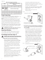
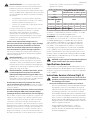
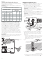
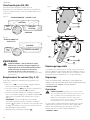
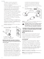
Grounding Instructions (Fig B, C)
DANGER: This machine must be grounded while
in use to protect the operator from electricshock.
1. All grounded, cord-connected machines:
-In the event of a malfunction or breakdown,
grounding provides a path of least resistance for
electric current to reduce the risk of electric shock.
This machine is equipped with an electric cord
having an equipment-grounding conductor and
a grounding plug. The plug must be plugged
into a matching outlet that is properly installed
and grounded in accordance with all local codes
andordinances.
-Do not modify the plug provided - if it will not fit
the outlet, have the proper outlet installed by a
qualifiedelectrician.
-Improper connection of the equipment-grounding
conductor can result in risk of electric shock. The
conductor with insulation having an outer surface
that is green with or without yellow stripes is
the equipment-grounding conductor. If repair or
replacement of the electric cord or plug is necessary,
do not connect the equipment-grounding
conductor to a liveterminal.
-Check with a qualified electrician or service
personnel if the grounding instructions are not
completely understood, or if in doubt as to whether
the machine is properlygrounded.
-Use only 3-wire extension cords that have 3-prong
grounding type plugs and matching 3-conductor
receptacles that accept the machine’s plug, as
shown in Fig.B.
-Repair or replace damaged or worn
cordimmediately.
GROUNDED OUTLET BOX
CURRENT
CARRYING
PRONGS
GROUNDING BLADE
IS LONGEST OF THE 3 BLADES
Fig. B
2. Grounded, cord-connected machines intended for
use on a supply circuit having a nominal rating less
than 150 Volts:
-If the machine is intended for use on a circuit that
has an outlet that looks like the one illustrated in
Fig. B, the machine will have a grounding plug that
looks like the plug illustrated in Fig. B. A temporary
adapter, which looks like the adapter illustrated
in Fig. C, may be used to connect this plug to a
matching 2-conductor receptacle as shown in
Fig.C if a properly grounded outlet is not available.
The temporary adapter should be used only until
a properly grounded outlet can be installed by
a qualified electrician. The green-colored rigid
ear, lug, and the like, extending from the adapter
must be connected to a permanent ground such
as a properly grounded outlet box. Whenever the
adapter is used, it must be held in place with a
metalscrew.
GROUNDED OUTLET BOX
GROUNDING MEANS
ADAPTER
Fig. C
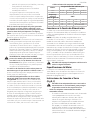
Minimum Gauge for Cord Sets
Volts Total Length of Cord in Feet
(meters)
120 V 25 (7.6) 50 (15.2) 100 (30.5) 150 (45.7)
240 V 50 (15.2) 100 (30.5) 200 (61.0) 300 (91.4)
Ampere Rating
American Wire Gauge
More
Than
Not
More
Than
0 6 18 16 16 14
610 18 16 14 12
10 12 16 16 14 12
12 16 14 12 Not Recommended

5
ENGLISH
SAVE THESE INSTRUCTIONS FOR
FUTURE USE
COMPONENTS FIG. A
Motor
Be sure your power supply agrees with the nameplate
marking. Voltage decrease of more than 10% will cause loss
of power and overheating. These tools are factory tested; if
this tool does not operate, check powersupply.
Intended Use
The CMEW020 is a 6" (152 mm), variable-speed bench
jointer intended for jointing and planing wood with a
designed cutting capacity of 6" (152 mm) wide and 1/8"
(3mm) deep. Unit includes a 10 Amp, 120Volt motor with
a variable speed range of 6000 to 11000RPM, and a cutting
speed range of 12000 to 22000CPM, a dust chute, a center-
mounted fence, a two-knife cutterhead, a cutterhead guard
and lock, wrenches, and pushblocks.
DO NOT use under wet conditions or in presence of
flammable liquids orgases.
DO NOT let children come into contact with the tool.
Supervision is required when inexperienced operators use
thistool.
NOTE: In Canada, the use of a temporary adapter is not
permitted by the Canadian ElectricCode.
DANGER: In all cases, make certain that the
receptacle in question is properly grounded. If
you are not sure, have a qualified electrician
check thereceptacle.
ASSEMBLY AND ADJUSTMENTS
WARNING: To reduce the risk of serious personal
injury, turn unit off and disconnect it from
power source before making any adjustments or
removing/installing attachments or accessories.
An accidental start-up can causeinjury.
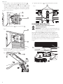
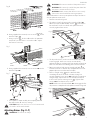
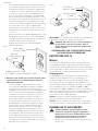
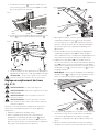
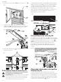
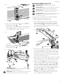
Fence (Fig. D–J)
1. Assemble the fence mounting bracket11 to the
jointer base using the four M6 x 1 mm x 16 mm button
headscrews12.
Fig.D
12
12
11
2. Assemble the fence sliding bracket3 to fence
mounting bracket11 using the lockhandle19, M8 flat
washer13 and special nut14.
Fig.E
14
Fig.F 3
19 13
Unpacking and Cleaning
Carefully unpack the machine and all loose items from the
shipping container(s). Remove the rust-preventative oil
from unpainted surfaces using a soft cloth moistened with
mineral spirits, paint thinner or denatured alcohol.
NOTICE: Do not use highly volatile solvents such as
gasoline, naphtha, acetone or lacquer thinner for
cleaning your machine.
After cleaning, cover the unpainted surfaces with a good
quality household floor pastewax.
Assembly Tools Required
Two hex wrenches (supplied)
Assembly Time Estimate
Assembly for this machine takes approximately 1hour.

ENGLISH
6
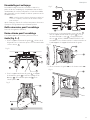
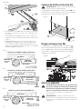
3. Insert a M6 x 1 mm x 16 mm button head screw16
through fence tilting bracket15 and thread a M6 x 1
square nut17 onto threaded end of screw16. DO NOT
COM PLETE LY TIGHTEN SCREW AT THIS TIME. Assemble
screw and square nut to opposite end of tilting bracket
in the samemanner.
15
Fig. G
16
17
4. Slide groove of fence18 over square nuts17.
Fig.H 18
17
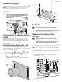
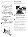
5. Position fence1 so that rounded section45 on
bottom of fence is over cutterheadopening.
Fig.I
45
6. Tighten two screws16 using included hexwrench.
Fig.J 16
Cutterhead Guard (Fig. K1)
WARNING: Keep hands away from the
cutterhead during use.
WARNING: Do not remove the cutterhead guard, do
not block the cutterhead guard, make sure cutterhead
guard spring back freely and touch the fence.
The cutterhead guard 2 is designed to rest against the
fence 1 . It will automatically move as the workpiece is
advanced toward the cutterhead and spring back against
the fence after the workpiece passes the cutterhead. With
the jointer off check for proper position and motion prior to
each operation. Always use the cutterhead guard.
21
Fig.K1

7
ENGLISH
OPERATION
WARNING: To reduce the risk of serious personal
injury, turn unit off and disconnect it from
power source before making any adjustments or
removing/installing attachments or accessories.
An accidental start-up can causeinjury.
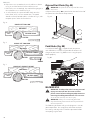
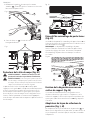
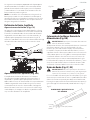
Cutterhead Lock (Fig. K2)
Assemble cutterhead lock4 to the front side of the jointer
base, using the M6 x 1 mm x 12 mm button head screw21.
NOTE: The cutterhead lock is to be engaged with the
cutterhead shaft only when setting knives. All other
times, the cutterhead lock should be disengaged from
thecutterhead.
21
4
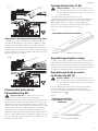
Fastening Jointer to Supporting Surface
(Fig. M)
If during operation, there is any tendency for the jointer
to tip over, slide or “walk” on the supporting surface, the
jointer must be secured to the supporting surface. Four
holes (two of which are shown at22 Fig.M, are provided
for thispurpose.
Dust Collector Hose Adapter (Fig. L, M)
A dust collector hose adapter23 is supplied with the
jointer to help connect it to a standard 2" (51 mm) vacuum
hose. To assemble the adapter:
1. Remove two screws25. Loosen screws26.
2. Slide adapter’s slots24 under loosened screws26.
3. Tighten screws26 when adapter23 is in
properlocation.
4. Replace and tighten screws25.
NOTICE: Do not install this vacuum hose adapter
unless you will be using a dust collector.
Fig.L
23
Fig.K2
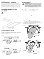
Stopping and Starting the Jointer
(Fig.A,N)
WARNING: Make sure that the switch is pressed
down so that the tool is turned "OFF" before
plugging in the power cord. In the event of a
power failure, press the switch down into the
"OFF" position. An accidental start-up can
causeinjury.
LOCKING THE SWITCH DOWN INTO THE "OFF" POSITION
NOTE: When the machine is not in use, the switch should
be locked in the down position to prevent unauthorized
use. Two holes27 are provided in the bottom of the switch
housing (Fig. N) for locking off the planer with apadlock.
To turn the planer on:
1. Lift up the switch5 (Fig. A). The planer locks on
automatically.
2. To turn the tool off, press the switch down.
Fig.N
27
Fig.M
25
26
22
22

ENGLISH
8
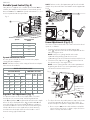
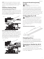
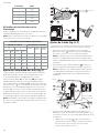
Variable Speed Control (Fig. O)
Your jointer is supplied with variable speed control6 that
enables you to operate the machine at cutterhead speeds
between 6000 and 11000 RPM. Speed indicators of 1, 2, 3, 4
and 5 are provided on the speeddial.
Fig.O
6
Speed Approximate
RPM
16000
27250
38800
49750
511000
Speed Selection Chart
Use the speed selection chart to determine the proper
setting for yourworkpiece.
NOTE: For convenience, make a copy of this chart and post
it on or near themachine.
SPEED SELECTION CHART
CUTTING WIDTH CONTROL SETTING
FROM TO PLASTICS SOFT
WOOD
HARD
WOOD
inches mm inches mm
0 0 1–1/2 38.1 1 1 1
1–1/2 38.1 2–1/2 65.5 2 2 3
2–1/2 63.5 3–1/4 82.5 3 3 4
3–1/4 82.5 4101.6 – 4 5
4101.6 6152.4 – 5 5
Depth of Cut Adjustment (Fig. P)
The jointer can be set to cut any depth from a very thin
shaving to 1/8" (3.2 mm) deep. A dual English/Metric
scale9, and pointer20 are provided to indicate the depth
of cut. To adjust for depth of cut, loosen lock knob8 and
turn table height adjustment knob7 clockwise to lower
and coun ter clock wise to raise the infeed table. Raising the
infeed table decreases the depth of cut, while lowering
it will increase the depth. After the infeed table is at the
desired setting, tighten lock knob.
NOTE: For best results, final positioning of the infeed table
should always be made from the bottom to the up position.
Fig. P
8
7
20
9
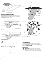
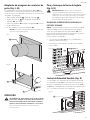
Fence Adjustments (Fig. Q–T)
The fence can be moved across the table and can be tilted
up to 45°, as follows:
1. To move the fence across the table, loosen lock
lever19, slide the fence to the desired position on the
table and tightenlever.
NOTE: Lock lever is spring loaded and can be
repositioned by pulling up on the lever and
repositioning it on the nut located underneath thelever.
2. To tilt the fence, loosen lever28 and tilt the fence to
the desired angle. Then tightenlever.
NOTE: Leveris spring loaded and can be repositioned
by pulling out on the lever and repositioning it on the
nut located underneath thelever.
Fig.Q
28
19
29
30
3. The fence features adjustable positive stops at the most
used fence positions of 90° and 45° to the right. To
check and adjust the positive stops, proceed as follows:
a. Place a square31 on the table with one end of the
square against the fence as shown. Adjust the fence
until it is exactly 90° to thetable.

9
ENGLISH
Fig.R
31
b. Using supplied hex wrench, turn set screw29 until it
contacts stop 30.
c. Using a square31, tilt the table to the 45° position
and make sure the fence is 45° to the table. Adjust
the fence ifnecessary.
Fig.S
d. Using supplied hex wrench, turn set screw32 until it
contacts stop33.
Fig.T 32
33
e. These positive stops enable you to rapidly position
the table to the 90° and 45°settings.
CAUTION: Make sure the fence is in level contact with
the surface of the outfeedtable.
Adjusting Knives (Fig. U–Y)
WARNING: The knives aresharp.
WARNING: Disconnect machine from powersource.
WARNING: Be extremely careful that your hands do
not come in contact with theknives.
WARNING: Make certain that all knives are securely
fastened in cutterhead before turning onpower.
When it becomes necessary to replace or adjust the knives
due to replacement or wear:
1. Remove cutterheadguard.
2. To replace a knife, disengage the cutterhead lock4.
Rotate cutterhead, loosen four screws34 and remove
bar and knife. Insert new knife and replace bar and
securely tighten four screws.
4
Fig.U
34
3. To adjust the knives, make sure the cutterhead lock4
is not engaged. Make sure screws are not overly
tightened. Loosen each one half turn or only enough so
knife can slide between locking plate andcutterhead.
4. Rotate cutterhead and engage cutterhead lock4 on
cutterhead shaft as shown. This will position knives for
proper adjustment to the outfeedtable.
5. Place a straight edge37 on the outfeed table
extending out over the knife as shown. Using hex
wrench supplied, turn screw35 until knife just touches
straight edge. Adjust knife at near end of cutterhead
in the same manner turning screw36. Tighten four
screws34 after adjustment ismade.
NOTE: Make sure cutterhead lock4 is disengaged after
adjustment is completed and replace cutterheadguard.
Fig.V
35
36
37
4

ENGLISH
10
6. If the knives are set too low, the result will be as shown
in Fig. W, and the finished surface will becurved.
7. If the knives are set too high, the work will be gouged at
the end of the cut, as shown in Fig.X.
8. As a final check, run a piece of work slowly over the
knives for 6" to 8" (152 mm to 203 mm). The wood
should rest firmly on both tables as shown in Fig. Y, with
no open spaces under the finishedcut.
KNIVES SET TOO LOW
OUT-FEED
TABLE IN-FEED TABLE
CUTTER
MATERIAL
Fig. W
KNIVES SET TOO HIGH
GOUGE
MATERIAL
IN-FEED TABLE
OUT-FEED
TABLE
CUTTER
Fig. X
KNIVES AT CORRECT HEIGHT
CUTTER
IN-FEED TABLE
OUT-FEED
TABLE
MATERIAL
Fig. Y
Chip and Dust Chute (Fig. AA)
WARNING: Keep hands out of chip and dust chute
at alltimes.
A chip and dust chute10 is provided on the outfeed end of
the jointer base for efficient chip removal.
Fig.AA
10
Push Blocks (Fig. BB)
A set of push blocks39 is supplied with your jointer
and should be used whenever possible to minimize all
danger to your hands. Fig. BB illustrates using the push
blocksproperly.
Fig.BB
39
MACHINE USE
WARNING: To reduce the risk of serious personal
injury, turn unit off and disconnect it from
power source before making any adjustments or
removing/installing attachments or accessories.
An accidental start-up can causeinjury.
WARNING: Always use cutterhead guard and
keep hands away from cutterhead. Use push blocks
wheneverpossible.
The following directions will give the beginner a start on
jointer operations. Use scrap pieces of lumber to check
the settings and to get the feel of the operations before
attempting regular work.

11
ENGLISH
NOTE: The knives on the jointer will not wear evenly by
feeding the wood through the same spot on the table
every time. Feed the wood through the jointer at different
spots on the table to help eliminate uneven wear of
theknives.
Definition of Jointing, Planing
Jointing Operations (Fig. CC)
Jointing cuts or edge jointing are made to square an edge
of a workpiece. The workpiece is positioned on the jointer
with the narrow edge of the workpiece on the infeed table
and the major flat surface of the workpiece against the
fence. The workpiece is moved from the infeed table, across
the cutterhead to the outfeedtable.
Fig.CC
Planing Operations (Fig. DD)
Planing or surfacing are identical to the jointing operation
except for the position of the workpiece. For planing, the
major flat surface of the workpiece is placed on the infeed
table of the jointer with the narrow edge of the workpiece
against the fence. The workpiece is moved from the
infeed table, across the cutterhead to the outfeed table.
Use push blocks when performing planing operations
wheneverpossible.
Fig.DD
Placement of Hands During Feeding
(Fig.BB)
WARNING: Never pass hands directly over
thecutterhead.
At the start of the cut, the left hand holds the work firmly
against the infeed table and fence, while the right hand
pushes the work toward the knives. After the cut is un der-
way, the new surface rests firmly on the outfeed table as
shown in Fig. BB. The left hand should then be moved to
the work on the outfeed table, at the same time maintaining
flat contact with the fence. The right hand presses the work
forward, and before the right hand reaches the cutterhead it
should be moved to the work on the outfeedtable.
Jointing an Edge (Fig. CC, EE)
WARNING: Do not perform jointing operations on
material shorter than 10" (254 mm), narrower than
3/4" (19 mm), or less than 1/2" (12.7 mm)thick.
This is the most common operation for the jointer. Set the
guide fence square with the table. Depth of cut should be
the minimum required to obtain a straight edge. Hold the
best face of the piece firmly against the fence throughout
the feed as shown in Fig.CC.
3/4" (19 mm) MIN I MUM
10" (254 mm) MINIMUM
MINIMUM JOINTING DIMENSIONS
1/2"
(12.7 mm)
MIN I MUM
Fig.EE
Planing Warped Pieces
If the wood to be planed is dished or warped, take light
cuts until the surface is flat. Avoid forcing such material
down against the table; excessive pressure will spring it
while passing the knives, and it will spring back and remain
curved after the cut iscompleted.
Planing Short or Thin Work (Fig. BB, FF)
WARNING: Do not perform jointing operations on
material shorter than 10" (254 mm), narrower than
3/4" (19 mm), or less than 1/2" (12.7 mm).
When planing short or thin pieces, always use push blocks
to minimize all danger to the hands. Fig. BB, illustrates using
the push blocks39 properly.

ENGLISH
12
Troubleshooting
For assistance with your machine, visit our website at
www.craftsman.com for a list of service centers or call the
help line at 1-888-331-4569.
Accessories
WARNING: Since accessories, other than those
offered by CRAFTSMAN, have not been tested with
this product, use of such accessories with this tool
could be hazardous. To reduce the risk of injury, only
CRAFTSMAN recommended accessories should be
used with thisproduct.
Recommended accessories for use with your tool are
available at extra cost from your local dealer or authorized
service center. If you need assistance in locating any
accessory, please contact CRAFTSMAN, call 1-888-331-4569.
MINIMUM AND
MAXIMUM PLANING
DIMENSIONS
1/2"
(12.7 mm)
MINIMUM 3/4"(19 mm) MINimum
6"
(152.4 mm) MAXIMUM
10" (254 mm) MINIMUM
Fig.FF
Direction of Grain (GG, HH)
Avoid feeding work into the jointer against the grain. The
result will be chipped and splintered edges. Feed with the
grain to obtain a smoothsurface.
IN-FEED TA BLE
OUT-FEED
TABLE
CUTTER
MATERIAL
CORRECT FEED - WITH THE GRAIN
Fig.GG
IN-FEED TABLE
OUT-FEED
TABLE
WRONG FEED -
AGAINST THE
GRAIN MATERIAL
Fig.HH
deflection in the belt43 at the center span of the
pulleys using light finger pressure. The belt does not
require excessive tension to functionproperly.
4. Replace belt guard41.
Fig.II
41
40
43
42
42
Fig.JJ
44
Failure to Start
Should your machine fail to start, check to make sure the
prongs on the cord plug are making good contact in the
outlet. Also, check for blown fuses or open circuit breakers
in theline.
MAINTENANCE
WARNING: To reduce the risk of serious personal
injury, turn unit off and disconnect it from
power source before making any adjustments or
removing/installing attachments or accessories.
An accidental start-up can causeinjury.
Belt Replacement (Fig. II, JJ)
When it becomes necessary to replace the belt on
yourjointer:
1. Remove screw40 using hex wrench supplied, and
remove belt guard41.
2. Loosen three screws42 to release belt tension and
remove belt43 frompulleys.
3. Assemble new belt to the cutterhead and motor pulleys.
Press down on motor pulley44 to tension belt and
tighten three screws.
NOTE: There should be approximately 1/4" (6.4 mm)

13
ENGLISH
Repairs
WARNING: To assure product SAFETY and
RELIABILITY, repairs, maintenance and adjustment
(including power cord repairs, and brush inspection
and replacement, when applicable) should be
performed by a CRAFTSMAN factory service center or
a CRAFTSMAN authorized service center. Always use
identical replacementparts.
Register Online
Thank you for your purchase. Register your product nowfor:
• WARRANTY SERVICE: Registering your product will
help you obtain more efficient warranty service in case
there is a problem with yourproduct.
• CONFIRMATION OF OWNERSHIP: In case of an
insurance loss, such as fire, flood or theft, your
registration of ownership will serve as your proof
ofpurchase.
• FOR YOUR SAFETY: Registering your product will
allow us to contact you in the unlikely event a safety
notification is required under the Federal Consumer
SafetyAct.
Register online at www.craftsman.com/registration
Cleaning
WARNING: Blow dirt and dust out of all air vents with
clean, dry air at least once a week. To minimize the risk
of eye injury, always wear ANSI Z87.1 approved eye
protection when performingthisprocedure.
WARNING: Never use solvents or other harsh
chemicals for cleaning the non-metallic parts of
the tool. These chemicals may weaken the plastic
materials used in these parts. Use a cloth dampened
only with water and mild soap. Never let any liquid
get inside the tool; never immerse any part of the tool
into aliquid.
Lubrication and Rust Protection
Apply household floor paste wax to the machine table,
extension table or other work surface weekly. You can also
use a commercially available protective product designed
for this purpose. Follow the manufacturer’s instructions for
use and safety.
To clean cast iron tables of rust, you will need the following
materials: a medium sized scouring pad, a can of spray
lubricant and a can of degreaser. Apply the spray lubricant
and polish the table surface with the scouring pad.
Degrease the table, then apply the protective product as
describedabove.
Three Year Limited Warranty
CRAFTSMAN will repair or replace, without charge, any
defects due to faulty materials or workmanship for three
years from the date of purchase. This warranty does not
cover part failure due to normal wear or tool abuse. For
further detail of warranty coverage and warranty repair
information, visit www.craftsman.com or call
1-888-331-4569. This warranty does not apply to
accessories or damage caused where repairs have been
made or attempted by others. THIS LIMITED WARRANTY
IS GIVEN IN LIEU OF ALL OTHERS, INCLUDING THE IMPLIED
WARRANTY OF MERCHANTABILITY AND FITNESS FOR A
PARTICULAR PURPOSE, AND EXCLUDES ALL INCIDENTAL
OR CONSEQUENTIAL DAMAGES. Some states do not allow
limitations on how long an implied warranty lasts or the
exclusion or limitation of incidental or consequential
damages, so these limitations may not apply to you. This
warranty gives you specific legal rights and you may have
other rights which vary in certain states orprovinces.
90 DAY MONEY BACK GUARANTEE
If you are not completely satisfied with the performance of
your CRAFTSMAN Power Tool or Nailer for any reason, you
can return it within 90 days from the date of purchase with
a receipt for a full refund – no questionsasked.
LATIN AMERICA: This warranty does not apply to products
sold in Latin America. For products sold in Latin America,
see country specific warranty information contained in
the packaging, call the local company or see website for
warrantyinformation.
FREE WARNING LABEL REPLACEMENT: If your warning
labels become illegible or are missing, call 1-888-331-4569
for a freereplacement.

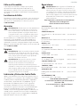
FRANÇAIS
14
Français (traduction de la notice d’instructions originale)
DESCRIPTION
1 Guide
2 Garde-protectrice de tête de coupe
3 Support de guide à glissière
4 Verrou de tête de coupe
5 Commutateur Marche/Arrêt
6 Commande de vitesse variable
7 Réglage de hauteur de la table
8 Bouton de verrouillage
9 Réglage de la profondeur
10 Chute à poussière
Définitions: symboles et termes d'alarmessécurité
Ces guides d'utilisation utilisent les symboles et termes d'alarmes sécurité suivants pour vous prévenir de situations
dangereuses et de risques de dommages corporels ou matériels.
DANGER : indique une situation dangereuse imminente qui, si elle n’est pas évitée, entraînera la mort ou des
blessuresgraves.
AVERTISSEMENT : indique une situation potentiellement dangereuse qui, si elle n’est pas évitée, pourrait entraîner la
mort ou des blessuresgraves.
ATTENTION : indique une situation potentiellement dangereuse qui, si elle n’est pas évitée, pourrait entraîner des
blessures légères oumodérées.
(Si utilisé sans aucun terme) Indique un message propre à la sécurité.
AVIS : indique une pratique ne posant aucun risque de dommages corporels mais qui par contre, si rien n’est fait
pour l’éviter, pourrait poser des risques de dommages matériels.
AVERTISSEMENT : lire tous les avertissements
de sécurité et toutes les directives. Le non-respect
des avertissements et des directives pourrait se
solder par un choc électrique, un incendie et/ou une
blessuregrave.
AVERTISSEMENT : ne jamais modifier l’outil
électrique ni aucun de ses composants, car il y a
risques de dommages corporels oumatériels.
AVERTISSEMENT : afin de réduire le risque de
blessures, lire le mode d’emploi del’outil.
Pour toute question ou remarque au sujet de cet outil
ou de tout autre outil CRAFTSMAN composez le
numéro sans frais : 1-888-331-4569.
1
2
3
6
5
4 7
8
9
10
Fig. A

FRANÇAIS
15
Banc de dégauchissage de 152mm (6po) à vitessevariable
CMEW020
Consignes générales de sécurité
1 . MAINTENEZ LES PROTECTEURS EN PLACE et en bon
état de fonctionnement.
2 . RETIREZ LES CLÉS DE RÉGLAGE. Prenez l'habitude de
vérifier si les clés de réglage ont été retirées de l’outil avant
de le mettre en marche.
3 . GARDEZ L'AIRE DE TRAVAIL PROPRE. Les établis et les
aires encombrés favorisent les blessures.
4 . NE PAS UTILISER DANS UN ENVIRONNEMENT
DANGEREUX. Ne pas utiliser les outils électriques dans
des endroits humides ou mouillés, ou exposés à la pluie.
Gardez l'aire de travail bien éclairée. Utilisez toujours l’outil
dans un endroit bien ventilé sans matières combustibles
ou vapeurs de solvants. Si des étincelles entrent en
contact avec des vapeurs inflammables, elles peuvent
s’enflammer, causant un incendie ou une explosion.
5 . GARDEZ LES ENFANTS LOIN. Tous les visiteurs devraient
être gardés à une distance sécuritaire de l'aire de travail.
6 . RENDEZ VOTRE ATELIER INACCESSIBLE AUX ENFANTS
à l'aide de cadenas, des principaux boutons ou en retirant
la clé de démarrage.
7 . NE PAS FORCER L’OUTIL. Il travaillera mieux et sera plus
sécuritaire à la vitesse pour laquelle il a été conçu.
8 . UTILISEZ LE BON OUTIL. Ne pas forcer l'outil ou
un accessoire à faire un travail pour lequel il n'a pas
étéconçu.
9 . UTILISEZ UNE RALLONGE APPROPRIÉE. Assurez-
vous que votre rallonge est en bon état. Lorsque vous
utilisez une rallonge, assurez-vous d’utiliser un calibre
suffisamment lourd pour faire circuler le courant qui
sera acheminé au produit. Un cordon de taille inférieure
entraînera une chute de tension de secteur entraînant une
surchauffe et une perte de puissance. Le calibre minimum
du tableau des cordons amovibles affiche la bonne
taille à utiliser selon la longueur de cordon et l’intensité
nominale de la plaque signalétique. En cas de doute,
utilisez le calibre le plus lourd suivant. Plus le numéro
de calibre est bas, plus le cordon est lourd. Lorsque vous
utilisez un outil électrique à l’extérieur, utilisez une rallonge
extérieure indiquée «W-A» ou «W». Ces rallonges sont
conçues pour une utilisation extérieure et réduire le risque
de choc électrique.
10 . PORTEZ DES VÊTEMENTS APPROPRIÉS. Ne pas porter
de vêtements lâches, des gants, cravate, bague, bracelet
ou autres bijoux qui pourraient se prendre dans les pièces
mobiles. Il est recommandé de porter des chaussures à
semelles antidérapantes. Portez une protection pour vos
cheveux afin de les retenir. Les évents couvrent souvent des
pièces qui se déplacent et doivent aussi être évités.
11 . UTILISEZ TOUJOURS DES LUNETTES DE SÉCURITÉ.
De plus, utilisez un masque facial ou antipoussière si
l’opération de coupe est poussiéreuse. Vos lunettes de tous
les jours peuvent ont des lentilles résistant aux impacts,
mais elles ne sont pas des lunettes de sécurité.
12 . SÉCURISEZ VOTRE TRAVAIL. Lorsque c’est possible,
utilisez des pinces ou un étau pour maintenir le travail.
C’est plus sécuritaire que d’utiliser vos mains et cela libère
vos deux mains pour faire fonctionner l’outil.
13 . NE PAS TROP S’ÉTIRER. Maintenez vos pieds bien
d’aplomb sur le sol et un bon équilibre en tout temps.
14 . ENTRETENEZ SOIGNEUSEMENT LES OUTILS. Pour
la meilleure et la plus sécuritaire performance, gardez
les outils aiguisés et propres. Suivez les instructions pour
lubrifier et changer les accessoires.
15 . DÉBRANCHEZ LES OUTILS avant l’entretien, lorsque vous
changez les accessoires comme les lames, les mèches, les
gouges et les accessoires semblables.
16 . RÉDUISEZ LE RISQUE DE DÉMARRAGE NON
INTENTIONNEL. Assurez-vous que le bouton Marche/
Arrêt est à la position Arrêt avant de brancher.
17 . UTILISEZ LES ACCESSOIRES RECOMMANDÉS. Pour les
accessoires recommandés, consultez le guide d’utilisation.
L’utilisation d’accessoires inappropriés peut causer un
risque de blessures.
18 . NE JAMAIS SE TENIR DEBOUT SUR L’OUTIL. Des
blessures graves pourraient vous être infligées si la table
bascule ou si vous venez en contact avec l’outil de coupe.
19 . VÉRIFIEZ LES PIÈCES ENDOMMAGÉES. Avant
l’utilisation ultérieure de l’outil, un protecteur ou une autre
pièce qui est endommagé doit être soigneusement vérifié
afin de déterminer s’il fonctionnera bien et s’il effectuera
la fonction prévue. Vérifiez l’alignement des pièces en
mouvement, le bris des pièces, le montage et tout autre
état qui peut affecter son utilisation. Tout protecteur ou
toute pièce endommagé devrait être adéquatement réparé
ou remplacé.
20 . SENS D’ALIMENTATION. Introduisez la pièce de travail
dans la raboteuse selon les flèches du sens d’alimentation
sur le dessus de l’outil.
21 . NE JAMAIS LAISSER L’OUTIL EN MARCHE SANS
SUPERVISION. COUPEZ L’ALIMENTATION.
Ne pas quitter les lieux avant que l’outil ne soit
complètementarrêté.
Règles de sécurité supplémentaires pour
les dégauchisseuses
AVERTISSEMENT: Ne pas suivre ces directives
peut entraîner des blessures graves.
1 . Ne pas faire fonctionner cet équipement avant qu’il
ait été complètement assemblé et installé selon les
instructions fournies. Une machine mal assemblée peut
causer des blessures graves.
2 . Si vous n’êtes pas complètement familier avec le
fonctionnement de cette machine, obtenez l’avis de

FRANÇAIS
16
votre superviseur, instructeur ou une autre personne
qualifiée. La connaissance est la sécurité
3 . Pour prévenir toute électrocution, lors du câblage,
suivre le/les codes de l’électricité applicables et faire
les raccordements recommandés.
4 . Garder les couteaux aiguisés et sans accumulation
de saleté ou de rouille. Les couteaux ébréchés ou
rouillés sont moins efficaces et peuvent causer un recul
intempestif.
5 . Avant de démarrer la machine, s’assurer que
les tables d’alimentation et de sortie sont bien
verrouillées. La perte de contrôle de la pièce de travail
pourrait causer des blessures graves.
6 . Avant de fermer le commutateur de marche, serrer
les lames adéquatement dans la tête de coupe. Les
lames mal serrées pourraient être projetées à haute vitesse.
7 . Ne jamais fermer le commutateur avant que la
table soit dégagée de tout objet (outil, retailles
de bois, etc.). Les débris projetés peuvent causer de
gravesblessures.
8 . Ne jamais démarrer la machine avec la pièce de
travail en contact avec la tête de coupe. Un recul
intempestif pourrait se produire
9 . Éviter les configurations insolites et le
positionnement dangereux des mains. Le glissement
soudain d’une pièce pourrait causer un déplacement de
votre main sur la tête de coupe.
10 . Pour prévenir les accidents de graves répercussions,
gardez vos bras, mains et doigts éloignés de la tête
de coupe.
11 . Pour prévenir le recul intempestif, ne jamais faire de coupe
plus profonde que 3,2mm (1/8po).
12 . Ne jamais joindre ou aplanir de pièce de travail
de moins de 254mm (10po) de longueur et de
19mm (3/4po) de largeur ou de moins de 12,7mm
(1/2po) d’épaisseur. Le jointage de pièces plus petites
peut placer votre main sur la tête de coupe, causant des
blessuresgraves.
13 . Pour joindre ou aplanir toute pièce de travail sous
le guide, utilisez un bloc de poussée/maintien sur
la table. Le jointage ou le dégauchissement de petites
pièces de travail peut résulter en un recul intempestif et des
blessures graves.
14 . Maintenez la pièce de travail fermement contre
la table et le guide. La perte de contrôle de la pièce
de travail pourrait causer un recul intempestif et des
blessuresgraves.
15 . Ne jamais faire de travail à main levée. Se servir du
guide pour positionner et diriger la pièce de travail.
La perte de contrôle de la pièce de travail pourrait causer
des blessures graves.
16 . Ne pas tenter d’effectuer une opération anormale
ou peu utilisée sans étudier la façon de procéder et
utiliser de montage, d’appareil, de butée ou de blocs
de maintien/poussée adéquats.
17 . Ne pas alimenter de pièce de travail par le côté de la
table de sortie de la machine. La pièce de travail serait
projetée de l’autre côté à grande vitesse.
18 . Pour prévenir le recul intempestif, ne pas alimenter
de pièce de travail qui est tordue, contient des
nœuds ou a des objets étrangés incrustés (clous,
broches, etc.).
19 . Maintenir la bonne relation des tables d’entrée et de
sortie avec le chemin de lame de la tête de coupe. La
perte de contrôle de la pièce de travail pourrait causer des
blessures graves.
20 . Supporter de façon adéquate les pièces de travail
de grande envergure de longueur ou de largeur. La
perte de contrôle de la pièce de travail pourrait causer
desblessures.
21 . Ne jamais effectuer de travail de configuration,
d’assemblage ou de positionnement de pièces sur
la table ou dans l’aire de travail lorsque la machine
est en marche. Le glissement soudain d’une pièce
pourrait causer un déplacement de votre main
sur la tête de coupe. Des blessures graves pourraient
êtrecausées.
22 . Pour prévenir les blessures, ne retirer les copeaux de
bois seulement après avoir ouvert le commutateur
de marche et que la tête de coupe soit arrêtée.
23 . Ouvrir le commutateur de marche, débrancher la
machine de sa prise de courant et nettoyer la table
et l’aire de travail avant de quitter la pièce. Pour
prévenir l’utilisation non autorisée, cadenasser le
commutateur de marche en position «OFF». D’autres
personnes incompétentes pourraient tenter d’utiliser la
machine et se blesser.
24 . De l’information supplémentaire concernant la
manipulation adéquate et sécuritaire d’outils
motorisés (par ex. une vidéo de sécurité) est
offerte par The Power Tool Institute, 1300 Sumner
Avenue, Cleveland, OH 44115-2851 (www.
Powertoolinstitute.Com). De l’information
est également disponible au National Safety
Council, 1121Spring Lake Drive, Itasca, IL 60143-
3201. Veuillez vous référer à l’American National
Standards Institute ANSI 01.1 Safety Requirements for
Woodworking Machines et au règlement OSHA 1910.213
du U.S. Department of Labor.
25 . Maintenez le protecteur de la tête de coupe en place
et en bon état de fonctionnement.
Consigne de sécurité supplémentaire
AVERTISSEMENT: porter SYSTEMATIQUEMENT
des lunettes de protection. Les lunettes courantes NE
sont PAS des lunettes de protection. Utiliser aussi un
masque antipoussières si l'opération est poussiéreuse.
PORTER SYSTÉMATIQUEMENT UN ÉQUIPEMENT DE
SÉCURITÉ HOMOLOGUÉ:
• Protection oculaire ANSI Z87.1 (CAN/CSA Z94.3);
• Protection auditive ANSI S12.6 (S3.19);
• Protection des voies respiratoires
NIOSH/OSHA/MSHA.

FRANÇAIS
17
AVERTISSEMENT: les scies, meules, ponceuses,
perceuses ou autres outils de construction peuvent
produire des poussières contenant des produits
chimiques reconnus par l’État californien pour causer
cancers, malformations congénitales ou être nocifs au
système reproducteur. Parmi ces produits chimiques,
on retrouve:
• Le plomb dans les peintures à base de plomb;
• La silice cristallisée dans les briques et le ciment,
ou autres produits de maçonnerie; et
• L’arsenic et le chrome dans le bois ayant subi un
traitementchimique.
Le risque associé à de telles expositions varie selon
la fréquence à laquelle on effectue ces travaux.
Pour réduire toute exposition à ces produits:
travailler dans un endroit bien aéré, en utilisant
du matériel de sécurité homologué, tel un masque
antipoussières spécialement conçu pour filtrer les
particulesmicroscopiques.
• Limiter toute exposition prolongée avec les
poussières provenant du ponçage, sciage, meulage,
perçage ou toute autre activité de construction.
Porter des vêtements de protection et nettoyer à
l’eau savonneuse les parties du corps exposées. Le
fait de laisser la poussière pénétrer dans la bouche, les
yeux ou la peau peut favoriser l’absorption de produits
chimiquesdangereux.
AVERTISSEMENT: cet outil peut produire et/
ou répandre de la poussière susceptible de causer
des dommages sérieux et permanents au système
respiratoire. Utiliser systématiquement un appareil
de protection des voies respiratoires homologué par
le NIOSH ou l’OSHA. Diriger les particules dans le sens
opposé au visage et aucorps.
AVERTISSEMENT: pendant l’utilisation, porter
systématiquement une protection auditive
individuelle adéquate homologuée ANSI S12.6
(S3.19). Sous certaines conditions et suivant la durée
d’utilisation, le bruit émanant de ce produit pourrait
contribuer à une perte de l’acuitéauditive.
• Prendre des précautions à proximité des évents,
car ils cachent des pièces mobiles. Vêtements amples,
bijoux ou cheveux longs risquent de rester coincés dans
ces piècesmobiles.
• Pour la sécurité de l’utilisateur, utiliser une rallonge
de calibre adéquat (AWG, American Wire Gauge
[calibrage américain normalisé des fils électriques]).
Plus le calibre est petit, et plus sa capacité est grande. Un
calibre16, par exemple, a une capacité supérieure à un
calibre18. L’usage d’une rallonge de calibre insuffisant
causera une chute de tension qui entraînera perte de
puissance et surchauffe. Si plus d’une rallonge est utilisée
pour obtenir une certaine longueur, s’assurer que chaque
rallonge présente au moins le calibre de fil minimum. Le
tableau ci-dessous illustre les calibres à utiliser selon la
longueur de rallonge et l’intensité nominale indiquée sur
la plaque signalétique. En cas de doute, utiliser le calibre
suivant. Plus le calibre est petit, plus la rallonge peut
supporter decourant.
Calibre minimum pour les cordons d'alimentation
Volts Longueur totale du cordon
d'alimentation en mètre (pieds)
120 V 7,6 (25) 15,2 (50) 30,5 (100) 45,7 (150)
240 V 15,2 (50) 30,5 (100) 61,0 (200) 91,4 (300)
Ampères
AWG
Plus que Pas plus
que
0 6 18 16 16 14
610 18 16 14 12
10 12 16 16 14 12
12 16 14 12 Non recommandé
Raccordements électriques
Un circuit électrique séparé doit être utilisé pour vos
machines. Ce circuit doit être inférieur à un fil no 12 et doit
être protégé avec un fusible temporisé 20 A.
REMARQUE : les fusibles temporisés devraient avoir
l’inscription « D » au Canada et « T » aux É.-U. Si on utilise
un cordon prolongateur, ce cordon doit être à trois fils,
avoir unefiche à trois broches et une prise de courant à
trois cavités, mise à la terre qui correspond à la fiche de
la machine. Avant debrancher la machine, s’assurer que
l’interrupteur (les interrupteurs) se trouve(nt) en position
«OFF» (ARRÊT) et que le courantélectrique présente les
mêmes caractéristiques que celles qui sont inscrites sur la
machine. Toutes les connexions électriquesdoivent établir
un bon contact. Le fonctionnement sur une basse tension
endommagera lamachine.
DANGER : ne pas exposer la machine à la pluie, et
ne pas l’utiliser dans des endroitshumides.
Spécifications du moteur
Cette machine est câblée pour un fonctionnement sur un
courant alternatif de 120 Volts 60 Hz. Avant de brancher la
machine, s’assurer que l’interrupteur se trouve à la position
«OFF » (ARRÊT).
Instructions de mise à la terre (Fig B, C)
DANGER : cette machine doit être mise à la terre
pendant son emploi, afin de protégerl’utilisateur
des déchargesélectriques.
1. Toutes les machines avec cordon mis à la terre:
-Dans l’éventualité d’un mauvais fonctionnement ou
d’unepanne, la mise à la terre fournit un trajet de
moindre résistance permettant de réduire le risque
de décharge électrique. Cette machine est dotée
d’un cordon électrique possédant unconducteur de
mise à la terre de l’équipement ainsi que d’unefiche
mise à la terre. La fiche doit être branchée dans une
prisede courant correspondante, installée de façon
adéquate etmise à la terre conformément à tous les
codes et règlementslocaux.
-Ne pas modifier la fiche fournie - si elle ne
s’adapte pas à laprise de courant, il faut faire
installer une prise de courant convenable par un
électriciencompétent.

FRANÇAIS
18
-Un mauvais raccordement du conducteur de mise
à la terrede l’équipement peut entraîner un risque
de décharge électrique. Le conducteur possédant
un isolant avec surface extérieure de couleur verte,
avec ou sans rayures jaunes, estle conducteur de
mise à la terre de l’équipement. Si uneréparation
ou un remplacement du cordon électrique s’avère
nécessaire, ne pas brancher le conducteur de mise à
la terrede l’équipement à une borne soustension.
-Consulter un électricien compétent ou le personnel
de service après-vente si on ne comprend pas
entièrement les instructions de mise à la terre, ou si
l’on doute que la machines oit correctement mise
à laterre.
-Utiliser seulement des cordons prolongateurs à trois
fils dotésd’une fiche mise à la terre, à trois broches,
et de prises à troiscavités convenant à la fiche de la
machine, comme l’illustre la FigureB.
-Réparer ou remplacer sans délai tout cordon
endommagéouusé.
BOÎTE À PRISES
MISE À LA TERRE
BROCHES
CONDUCTRICESDE
COURANT
LA BROCHE DE MISE
ÀLA TERRE EST LA PLUS LONGUEDES TROIS
Fig. B
2. Machines avec cordon mis à la terre prévues pour
uneutilisation sur une alimentation nominale
inférieure à 150 Volts:
-Si cette machine est prévue pour être utilisée
sur un circuit quicomporte une prise semblable
à celle illustrée à la Figure B, la machine devra
comporter une fiche mise à la terre semblableà celle
illustrée à la Figure B. Un adaptateur temporaire
semblable à celui illustré à la Figure C, peut être
utilisé pour raccorder cette fiche à une prise à
deux cavités comme celle illustrée à la FigureC,
si une prise correctement mise à la terren’est
pas disponible. L’adaptateur temporaire ne doit
êtreutilisé que jusqu’au moment où une prise
correctement miseà la terre est installée par un
électricien compétent. L’oreillerigide ou autre
dispositif semblable de couleur verte, sur ledessus
de l’adaptateur, doit être connecté sur une mise
à laterre permanente comme, par exemple une
boîte à prisescorrectement mise à la terre. Quand
un adaptateur est utilisé, celui-ci doit être retenu en
place par une vis enmétal.
OÎTE À PRISES
MISE À LA TERRE
OREILLE DE MISEÀ
LA TERRE
ADAPTATEUR
Fig. C
REMARQUE: au Canada, le Code canadien de l’électriciténe
permet pas l’emploi d’un adaptateurtemporaire.
DANGER : dans tous les cas, s’assurer quela prise
en question est bien mise à la terre. Dans le
doute, demander à un électricien compétentde
vérifier laprise.
CONSERVER CES CONSIGNES POUR
UTILISATION ULTÉRIEURE
DESCRIPTION FIG. A
Moteur
S’assurer que le bloc d’alimentation est compatible avec
l’inscription de la plaque signalétique. Une diminution de
tension de plus de 10 % provoquera une perte de puissance
et une surchauffe. Les outils sont testés en usine; si cet outil
ne fonctionne pas, vérifier l’alimentationélectrique.
Usage prévu
La CMEW020 est une dégauchisseuse d’établi à vitesse
variable 152 mm (6 po) destinée à l’assemblage et le
rabotage du bois ayant une capacité de coupe conçue
d’une largeur de 152 mm (6 po) et d’une profondeur de
3mm (1/8 po). L’appareil comporte un moteur de 120 Volts,
10 A, une plage de vitesses variables de 6000–11000 tr/
min produisant 12000–22000 courses/min, une goulotte à
poussière, un guide monté au centre, un porte-outils à deux
lames, un dispositif de protection et de verrouillage des
lames, des clés et des blocs-poussoirs.
NE PAS les utiliser en milieu ambiant humide ou en
présence de liquides ou de gazinflammables.
NE PAS le laisser à la portée des enfants. Une supervision
est nécessaire auprès de tout utilisateur nonexpérimenté.
ASSEMBLAGE ET AJUSTEMENTS
AVERTISSEMENT : afin de réduire le risque
de blessure corporelle, éteignez l’appareil et
débranchez-le la source d’alimentation avant
d’effectuer tout ajustement ou de retirer/
installer des pièces ou des accessoires. Un
déclenchement accidentel du démarrage peut causer
des blessures.
La page charge ...
La page charge ...
La page charge ...
La page charge ...
La page charge ...
La page charge ...
La page charge ...
La page charge ...
La page charge ...
La page charge ...
La page charge ...
La page charge ...
La page charge ...
La page charge ...
La page charge ...
La page charge ...
La page charge ...
La page charge ...
La page charge ...
La page charge ...
La page charge ...
La page charge ...
La page charge ...
La page charge ...
La page charge ...
La page charge ...
La page charge ...
La page charge ...
-
 1
1
-
 2
2
-
 3
3
-
 4
4
-
 5
5
-
 6
6
-
 7
7
-
 8
8
-
 9
9
-
 10
10
-
 11
11
-
 12
12
-
 13
13
-
 14
14
-
 15
15
-
 16
16
-
 17
17
-
 18
18
-
 19
19
-
 20
20
-
 21
21
-
 22
22
-
 23
23
-
 24
24
-
 25
25
-
 26
26
-
 27
27
-
 28
28
-
 29
29
-
 30
30
-
 31
31
-
 32
32
-
 33
33
-
 34
34
-
 35
35
-
 36
36
-
 37
37
-
 38
38
-
 39
39
-
 40
40
-
 41
41
-
 42
42
-
 43
43
-
 44
44
-
 45
45
-
 46
46
-
 47
47
-
 48
48


Craftsman CMEW020 Manuel utilisateur
- Catégorie
- Outils électroportatifs
- Taper
- Manuel utilisateur
dans d''autres langues
- English: Craftsman CMEW020 User manual
- español: Craftsman CMEW020 Manual de usuario