La page est en cours de chargement...

This kit provides for the installation of a unified grille panel
for a framed or overlay custom panel. The panel will span
the combined width of a side by side installation.
Completion Time: Allow approximately 2 hours to install
this kit.
IMPORTANT: 2 People are required to install this kit.
Disconnect power before you begin.
Installation
Instructions
ZKBSN720NSS - Stainless Steel
Unification Kit and
ZKBFN720NII Panel Unification Kit
CONTENTS:
DESIGN GUIDE
STANDARD INSTALLATION - Case Flush to Cabinet
with Proud Doors
The Installation Space ...................... 2
Dimensions and Clearances ................. 2
Grille Panel Dimensions .................... 3
DESIGN GUIDE
FLUSH INSTALLATION - Case Inset to Cabinet with
Flush Doors
The Installation Space ...................... 3
INSTALLATION INSTRUCTIONS
MATERIALS ................................ 4
GROUNDING THE REFRIGERATOR ............ 5
STEP 1. REMOVE PACKAGING ................ 6
STEP 2. INSTALL WATER LINES .............. 6
STEP 3. INSTALL NEW CENTER TRIM ......... 7
STEP 4. REMOVE BOTH GRILLE PANEL
FRAMES ........................... 7
STEP 5. INSTALL SIDE PANELS .............. 7
STEP 6. INSTALL ANTI-TIP BRACKET .......... 8
STEP 7. POSITION REFRIGERATOR AND
INSTALL TOP TRIM .................. 9
STEP 8. LEVEL REFRIGERATOR ............. 10
STEP 9. INSTALL ANTI-TIP BRACKET ......... 11
STEP 10. SECURE REFRIGERATOR
TO CABINETRY ................... 13
STEP 11A. INSTALL UNIFIED PANEL FRAME . . 14
STEP 11B. INSTALL STAINLESS STEEL
GRILLE PANEL .................. 15
STEP 12. INSTALL CENTER TRIM STRIP ...... 15
STEP 13. ADJUST DOOR SWING ............. 15
STEP 14. CHECK AND CORRECT DOOR
ALIGNMENT ...................... 16
STEP 15. INSTALL GRILLE BASE ............ 18
STEP 16. CONNECT WATER SUPPLY ......... 18
STEP 17. CONNECT POWER ................ 19
STEP 18A. INSTALL STAINLESS STEEL
TOEKICK ....................... 19
STEP 18B. INSTALL CUSTOM TOEKICK FOR
STANDARD INSTALLATION ........ 19
STEP 18C. INSTALL CUSTOM TOEKICK FOR
FLUSH INSET INSTALLATION ...... 19
To consult a French or Spanish version of this instruction manual, visit our Monogram.com website.
In Canada, visit Monogram.ca.
BEFORE YOU BEGIN
Read these instructions completely and carefully.
• IMPORTANT – Save these instructions for local inspector’s use. Observe all governing codes and ordinances.
• Note to Installer – Be sure to leave these instructions with the Consumer.
• Note to Consumer – Keep these instructions with your Owner’s Manual for future reference.
If you received a damaged unit, you should immediately contact your dealer or builder.
Skill Level – Installation of this unit requires basic mechanical, carpentry and plumbing skills. Proper installation
is the responsibility of the installer. Product failure due to improper installation is not covered under the Monogram
Warranty. See the Owner’s Manual for warranty information.
WARNING
Fire or Explosion Hazard. Keep flammable materials and vapors away from
appliance. Failure to do so can result in fire, explosion, or death.
WARNING
To reduce the risk associated with choking, do not allow children under 3 years of age to
have access to small parts during the installation of this product.

THE INSTALLATION SPACE
The installation space must be 71-1/2” wide.
Water and Electrical Locations
The water and electrical locations for each product must
be located as shown.
The cutout depth must be 24”
The refrigerator will project forward, slightly beyond
adjacent cabinetry, depending on your installation.
Cutout depth beneath a soffit:
When installed beneath a soffit, the soffit cannot exceed
the 24” installation depth shown. The top case trim
overlaps the bottom of the soffit.
Additional Specifications
ƒ A separate 115 volt, 60Hz, 15 or 20 amp power supply
is recommended for each product. An individual
properly grounded branch circuit or circuit breaker
is recommended. Install properly grounded 3-prong
electrical receptacles recessed into the back wall.
Electrical must be located on rear wall as shown.
NOTE: GFI (ground fault interrupter) is not
recommended.
ƒ Both water lines can enter the opening through the
floor or back wall. Route SmartConnect™ kit or 1/4”
O.D. copper tubing between the cold water line and
the water connection location. The tubing should be
long enough to extend t the front of the refrigerator.
Installation of an easily accessible shut-off valve in the
water line is required.
DIMENSIONS AND CLEARANCES
Product and Clearances
These refrigerators are equipped with a 3-position door
stop. The factory set 115° door swing can be adjusted
to 90° if clearance to adjacent cabinets or walls is
restricted.
Allow 25" minimum clearance for a full 130 door swing.
Allow 15" for pan removal.
5" minimum clearance is required when door swing is
adjusted to 90. If the 90 door stop position is used, pan
access is maintained, but pan removal is restricted.
See illustrations to determine door swing interaction with
adjacent cabinets or countertops.
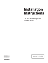
DESIGN GUIDE - STANDARD INSTALLATION
25”
Min. to
Wall
25”
Min. to
Wall
1”
130° Door
Swing
130° Door
Swing
71-1/2"
Case Width
25-3/4"
Case Depth
28-1/2" Depth
Including Handles
72" Frame to
Frame Width
*Shipping height. The
refrigerators can be adjusted
to fit into a cutout that is
83-1/2" min. to 84-1/2" max.
Note that the top case trim
at the front is 1/2" higher and
will overlap upper cabinetry
or soffit. Use leveling legs
and wheels for a maximum
1" height adjustment.
*84"
83-1/2"
at Rear
23-7/8"
Behind
Frame
36-3/4"
4" Minimum
to Wall
90°
2
31-1000414 Rev. 1

DESIGN GUIDE - STANDARD INSTALLATION
DESIGN GUIDE - FLUSH INSTALLATION
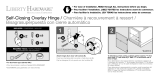
REQUIRED DIMENSIONS FOR GRILLE PANELS
Panels must be cut to the dimensions shown.
IMPORTANT NOTE: The maximum weight for the unified
grill is 25 pounds.
Assemble the overlay panels as shown, using glue and
screws. Center the spacer panel on the backer panel.
Center the overlay panel on the backer and spacer panel.
A
B
Grille Panel
Framed Panel Dimensions
1/4” (0.63 cm)
Framed Panel
A (Width) B (Height)
69-7/8” (177.48 cm) 8-7/8” (22.54 cm)
Overlay Panel Dimensions
1/4” (0.63 cm)
Backer Panel
A (Width) B (Height)
69-7/8” (177.48 cm) 8-7/8” (22.54 cm)
0.10” (0.25 cm)
Spacer Panel
68-1/2” (97.79 cm) 7-5/8” (20 cm)
3/4” (1.9 cm)
Overlay Panel
70-1/8” (178.12 cm) 9” (22.86 cm)
INSTALLATION SPACE
See ZKFN Kit for Installation Space, Unified Door
Panel Dimensions, Unified Grille Panel Dimensions,
Side Cleats, and Toe Kick Dimensions.
3
31-1000414 Rev. 1

INSTALLATION INSTRUCTIONS
Tools Required:
• Tinsnips to cut banding
• Stepladder
• Bucket
• Level
• Appliance dolly
• Tubing cutter
• 7/16" open-end wrench
• #1 and #2 Phillips screwdrivers
• Drill and appropriate bits
• 5/16", 7/16" socket
• Safety glasses
• 1-1/4" open-end wrench
• Pliers
• 1/4" ratchet or 1/4" angled wrench
• Tape measure
• Gloves to protect against sharp edges
Hardware Supplied:
• Water filter bypass plug
•Anti-tip brackets
•1/4" nut and ferrule
Parts List:
A. Top trim
B. Left inside case trim
C. Right inside case trim
D. Center U-shape trim
E. Grille base wrap
F. Grille panel
G. Foam spacer pads (6)
H. Toekick
HH. Toekick skirt
I. Phillips screws (28)
J. Package of 12 plastic spacers
K. 2 Corner trim brackets
L. Black #8-32 x 3/8" screws (12)
M #6-32 x .340 screws (4)
Materials Required:
• 71" long 2x4 for Anti-Tip support
• 1/4" copper water line tubing or 2 SmartConnect™
Refrigerator Tubing kits
• 2 Water shut-off valves
• Screws to secure refrigerator to cabinetry
• Stick-on hook and loop fastener strips for 1/4" side
panels.
Flooring:
For proper installation, this refrigerator must be placed
on a level surface of hard material that is at the same
height as the rest of the flooring. This surface should be
strong enough to support a fully loaded refrigerator, or
approximately 2,400 lbs.
NOTE: Protect the finish of the flooring. Cut a large
section of the cardboard carton and place under the
refrigerator where you are working.
A
B
C
D
E
F
H
G
I
J
M
L
K
HH
4
31-1000414 Rev. 1

GROUNDING THE REFRIGERATOR
WARNING
Electrical Shock Hazard.
Failure to follow these instructions can result in death,
fire, or electrical shock.
The power cord of this appliance is equipped with a
3-prong (grounding) plug which mates with a standard
3-prong (grounding) wall receptacle to minimize the
possibility of electric shock hazard from this appliance.
Have the wall outlet and circuit checked by a qualified
electrician to make sure the outlet is properly grounded.
Where a standard 2-prong wall outlet is encountered, it
is your personal responsibility and obligation to have it
replaced with a properly grounded 3-prong wall outlet.
DO NOT, UNDER ANY
CIRCUMSTANCES, CUT OR
REMOVE THE THIRD (GROUND)
PRONG FROM THE POWER
CORD.
DO NOT USE AN ADAPTER
PLUG TO CONNECT THE REFRIGERATOR TO A
2-PRONG OUTLET.
DO NOT USE AN EXTENSION CORD WITH THIS
APPLIANCE.
INSTALLATION INSTRUCTIONS
MISE À LA TERRE DU
RÉFRIGÉRATEUR
AVERTISSEMENT
Risque de choc élec-
trique.
Le non-respect de ces instructions peut entraîner des risques
d’incendies, des chocs électriques ou la mort.
Le cordon d’alimentation de cet appareil est équipé d’une
fiche à trois broches (pour une mise à la terre) qui s’adapte à
la prise de courant standard à 3 broches (pour une mise à la
terre) pour minimiser les risques de chocs électriques par cet
appareil.
Faites vérifier la prise murale et le circuit électrique par un
électricien qualifié pour s’assurer que le système est correc-
tement mis à la terre.
Dans le cas d’une prise biphasée, l’installateur a la respon-
sabilité et l’obligation de la remplacer par une prise triphasée
correctement mise à la terre.
NE COUPEZ PAS OU N’ENLEVEZ PAS, SOUS AUCUN
PRÉTEXTE, LA TROISIÈME BROCHE DE MISE À LA
TERRE DU CORDON D’ALIMENTATION.
N’UTILISEZ PAS D’ADAPTATEUR
POUR BRANCHER LE
RÉFRIGÉRATEUR À UNE PRISE
BIPHASÉE.
N’UTILISEZ PAS DE RALLONGE
AVEC CET APPAREIL.
CONEXIÓN A TIERRA DEL
REFRIGERADOR
ADVERTENCIA
Riesgo de Descarga
Eléctrica
Si no se siguen estas instrucciones, se podrá producir la
muerte, incendios o descargas eléctricas.
El cable de corriente de este electrodoméstico cuenta con un
enchufe de 3 cables (conexión a tierra) que se conecta a un
tomacorriente de pared estándar de 3 cables (conexión a tie-
rra) para minimizar el riesgo de posibles descargas eléctricas
por parte del mismo.
Contrate a un electricista calificado para que controle el
tomacorriente y el circuito eléctrico, a fin de asegurar que el
enchufe esté correctamente conectado a tierra.
En caso de contar con un tomacorriente de pared de 2
cables, es su responsabilidad y obligación reemplazarlo por
un tomacorriente de pared de 3 cables correctamente conec-
tado a tierra.
NUNCA, BAJO NINGUNA CIRCUNSTANCIA, CORTE NI
ELIMINE EL TERCER CABLE (TIERRA) DEL
CABLE DE CORRIENTE.
NO USE UN ENCHUFE ADAPTADOR PARA
CONECTAR EL REFRIGERADOR A UN
TOMACORRIENTE DE 2 PATAS.
NO USE UN PROLONGADOR CON ESTE
ELECTRODOMÉSTICO.
5
31-1000414 Rev. 1

INSTALLATION INSTRUCTIONS
STEP 1 REMOVE PACKAGING
WARNING
Tip Over Hazard.
The refrigerator is much heavier at the top than at the
bottom—be careful when moving. When using a hand
truck, handle from the side only.
AVERTISSEMENT
Risque de
basculement Le réfrigérateur est beaucoup plus lourd en
haut qu’en bas. Il faut être prudent lors des déplacements. Si
un diable est utilisé, il faut soulever le réfrigérateur sur le côté
seulement.
ADVERTENCIA
Riesgo de Caídas
El refrigerador es mucho más pesado en su parte superior
que en su parte inferior – tenga cuidado al moverlo. Al usar
un carro manual, sosténgalo de costado únicamente.
• Carefully cut banding at the top and
bottom, remove the outer carton.
• Slide out the back corner posts (2).
• Slide the carton off the top of the
cabinet.
NOTE: IT IS NOT NECESSARY
TO LAY THE CABINET DOWN IN
ORDER TO REMOVE THE SKID!
• The unit is secured to the skid with
4 slotted tie-down straps. Remove
the four 5/16” bolts from the base channels in the tie-
downs.
• Remove the four 7/16” bolts securing the straps to the
skid.
NOTE: DO NOT ATTEMPT TO ROLL UNIT OFF SKID.
• The support blocks on the bottom of the refrigeration
case must be removed before the refrigerator is taken
off the skid or damage will occur. Carefully tilt the
refrigerator and slide the blocks out from beneath.
• Remove the tape from the leveling legs.
• Lift the refrigerator off the skid with an appliance dolly.
Handle from the sides.
STEP 2 INSTALL WATER LINES
• Route 1/4” OD copper or SmartConnect
™
plastic
tubing between house cold water line and the water
connection location.
• Tubing should be long enough to extend to the front of
the refrigerator. Allow enough tubing to accommodate
bend leading into the water line connection.
NOTE: The only Monogram-approved plastic tubing is
supplied in the SmartConnect
™
Refrigerator Tubing
kits. Do not use any other plastic water supply line
because the line is under pressure at all times. Other
types of plastic may crack or rupture with age and
cause water damage to your home.
SmartConnect
™
Refrigerator Tubing Kits are available
in the following lengths:
2’ (.6 m) - WX08X10002 15’ (4.6 m) - WX08X10015
8’ (2.4 m) - WX08X10006 25’ (7.6 m) - WX08X10025
Shut off the main water supply.
Turn on the nearest faucet long enough to clear the
line of water.
• Install a shut-off valve between the icemaker water
valve and cold water pipe in a basement or cabinet.
The shut-off valve should be located where it will be
easily accessible.
• Turn on the main water supply and flush debris.
Run about a quart of water through the tubing into a
bucket. Shut off water supply at the shut-off valve.
NOTE: Saddle type shut-off valves are included in
many water supply kits, but are not recommended for
this application.
If the water supply to the refrigerator is from
a Reverse Osmosis Water System, use the
refrigerator’s filter bypass plug. Using the
refrigerator’s water filtration cartridge with the RO
filter can result in hollow ice cubes.
STEP 2 INSTALL WATER LINES
WARNING
Connect to potable water supply
only.
AVERTISSEMENT
Raccordez l’appareil à une ali-
mentation d’eau potable seulement.
ADVERTENCIA
Realice la conexión a un sumi-
nistro de agua potable únicamente.
• A cold water supply is required for automatic
icemaker operation. The water pressure must be
between 40 and 120 p.s.i. (275-827 kPa).
NOTE: Commonwealth of Massachusetts Plumbing
Codes 248CMR shall be adhered to. Saddle
valves are illegal and use is not permitted in
Massachusetts. Consult with your licensed plumber.
Floor
Waterline
Tubing
Filter Bypass Plug
6
31-1000414 Rev. 1

STEP 3 INSTALL NEW CENTER
TRIM
NOTICE: Handle parts with care to avoid scratching.
A. Remove the factory installed inside case trims and
top case trims.
B. Install inside case trims (B & C) with notches toward
the bottom. Install screws (I) through 5 slots on each
trim.
C. Apply the supplied foam spacer pads (G) to the
mating side of one product as shown.
NOTE: Flush inset installations require Kit ZKFN. The
ZKFN Kit includes hinge side case trims that should be
installed at this step. The hardware required to install
these trims is included in the ZKFN Kit.
STEP 4 REMOVE BOTH GRILLE
PANEL FRAMES
• Remove 2 or 3 screws holding the grille panel to the
hinge on each side. Lift grille panel off the hinges.
Discard both grille panels. Retain screws or use (L)
screws supplied.
Leave hinges in the open position.
Do not push hinges back.
STEP 5 INSTALL SIDE PANELS
Side panels must be used whenever the sides of the
refrigerator will be exposed. The 1/4” (0.63 cm) side
panels will slip into the side case trim. Secure the
panels to the refrigerator with stick-on hook and loop
fastener strips. Order the side panels from the cabinet
manufacturer.
• Cut a notch in the top front corner as shown to allow
clearance for corner keys in the front side trim.
INSTALLATION INSTRUCTIONS
Foam
Spacer
Pads
*84"
2-9/16"
24"
*3" to 4"
3/16"
1-7/8"
* Depending on
installation height.
Grille Panel
Remove
2 Screws
Stiffeners
Remove 3
Screws
Grille Panel
7
31-1000414 Rev. 1

STEP 6 INSTALL ANTI-TIP BRACKET
WARNING
Tip Over Hazard.
These refrigerators are top heavy, especially with any
doors open, and must be secured to prevent tipping
forward which could result in death or serious injury.
Read and follow the entire installation instructions for
securing the refrigerator with the anti-tip system.
AVERTISSEMENT
Risque de
basculement Ces réfrigérateurs présentent une
partie supérieure lourde, en particulier avec une porte
ouverte; ils doivent donc être fixés pour prévenir le
basculement vers l’avant et le risque concomitant
de blessure grave ou fatale. Lisez et suivez les
instructions d’installation complètes pour l’installation
du système anti-basculement.
ADVERTENCIA
Riesgo de Caídas
Estos refrigeradores son inestables, especialmente cuando
una puerta se encuentre abierta, y deberán estar asegurados
a fin de evitar caídas hacia adelante que podrían resultar en
la muerte o en lesiones graves. Lea y siga las instrucciones
de instalación en su totalidad para asegurar el refrigerador
con el sistema anti volcaduras.
ƒ&XWDƎ[Ǝ[ƎEORFNDQGVHFXUHWKHEORFNWRWKH
mounting brackets provided using #12 or #14 wood
screws.
ƒ Secure the bracket with wood block to the back wall so
WKDWLWLVƎRU\RXULQVWDOODWLRQKHLJKWIURPWKHILQLVKHG
floor. Use #12 or #14 wood screws. See illustration.
ƒ Screws must penetrate at least one inch into vertical
wall studs.
ƒ Before pushing the refrigerator into the opening, plug
the power cord into the receptacle. Open the grille panel
and reach into the opening at the back to grasp the
power cord. Pull the power cord into the opening as you
push the refrigerator back.
ƒ Gently push refrigerator into the opening with hands
against front corners.
IMPORTANT: When the refrigerator is installed under
a soffit or if there is not enough height for this method
of security, brackets cannot be used. Proceed to step
8 to level the refrigerator and then to step 10 to secure
refrigerator to cabinets. The refrigerator must be secured
to prevent tipping.
INSTALLATION INSTRUCTIONS
2x4 Cut
71" Length
Installation Height
From Floor
Screws Mounted into
Vertical Wall Studs
Mounting
Bracket
Brackets
Required
Height
From
Floor to
Bottom
of
Wood
Block
Side View
Block
6RႈW
Brackets
Not
Required
Beneath a
6RႈW
8
31-1000414 Rev. 1

STEP 7 POSITION REFRIGERATOR AND INSTALL TOP TRIM
• Before pushing the refrigerators into the
opening, plug the power cords into the
receptacles. Reach into the top opening
to grasp the power cord. Pull the power
cord into the opening as you push the
refrigerator back.
• With hands against front corners,
push one refrigerator part-way into the
opening. The refrigerator should be
DSSUR[LPDWHO\ƎIRUZDUGRIWKHEDFN
wall.
• Gently push the second refrigerator next
to the other. The doors should be flush to each other
and the inside trims together.
• Install corner bracket (K) into each side of the top trim
(A). Use 4 screws (M) if needed.
• Place the top trim across the top of the refrigerators
and slip the corner brackets into the outside case
trims.
• Install 8 screws (I) through the top of the trim and into
the top case.
• Check to be sure the inside trims are aligned top and
bottom. There should be a slight gap between the
case trims.
• Remove the Grill Base wraps. 6 screws will be
removed from each grille base wrap. Keep the screws
for future steps.
PUSH REFRIGERATOR INTO OPENING
NOTE: 2 PEOPLE ARE REQUIRED TO PUSH THE
UNIFIED REFRIGERATORS INTO THE OPENING.
• With hands against the front corners, gently push the
unified refrigerators into the opening or against the
back wall.
Soffit
$SSUR[Ǝ
Corner Trim
Bracket
INSTALLATION INSTRUCTIONS
9
31-1000414 Rev. 1

STEP 8 LEVEL REFRIGERATOR
Place a level inside the top of each unit.
Both refrigerators MUST BE LEVEL AND PLUMB with
each other and with adjacent cabinetry on each side.
Drawers should be evenly aligned.
Both refrigerators have 4-point leveling. The front is
supported by leveling legs, the rear is supported by
adjustable wheels. Both are accessible from the front of
the refrigerator.
7ROHYHOWKHEDFNRIWKHUHIULJHUDWRUWXUQWKHƎKH[
nut located above the front wheels. Turn clockwise to
raise or counterclockwise to lower the refrigerator.
)RUIURQWOHYHOLQJXVHDƎRSHQHQGZUHQFK
• Adjust height of refrigerator to match installation cutout
RSHQLQJWRƎ7KHUHIULJHUDWRUVKRXOGEH
level and plumb with cabinetry.
The rear leveling wheels and front leveling legs are lim-
ited to a maximum height adjustment of 1” (2.54 cm). If
the installation requires more than 84-1/2” (214.63 cm)
height, the installer should elevate the refrigerator on a
sheet of plywood or runners. Cabinetry trim could also
be added across the top of the opening to shorten the
opening. If you attempt to raise the refrigerator more
than 1” (2.54 cm), you will damage the front leveling
legs and the rear leveling wheels.
INSTALLATION INSTRUCTIONS
Hex Nut Adjusts
Rear Wheels
Leveling Leg
10
31-1000414 Rev. 1

STEP 9 INSTALL ANTI-TIP BRACKET
WARNING
Tip Over Hazard.
The unit is top-heavy and must be secured to prevent
the possibility of tipping forward.
AVERTISSEMENT
Risque de
basculement
L’appareil ménager est beaucoup plus lourd
en haut et il faut le maintenir en place pour éviter la possibilité
de son basculement vers l’avant.
ADVERTENCIA
Riesgo de Caídas
La unidad es pesada en su parte superior y se deberá asegu-
rar a fin de evitar posibles caídas hacia adelante.
• The kit supplied with the unit contains 2 lag bolts and 4
toggles with bolts. The wall bracket will be attached to
the wall in 4 places.
• Measure the opening where the unit is to be installed.
Mark the center with a vertical line.
• Measure up 81-1/2” (207.01 cm) from the floor. Mark
this point on the wall.
• Using a level, draw a horizontal line on the wall at this
height.
• Locate at least 2 studs on the back wall. Mark these
points on the horizontal line.
• Place the bottom of the wall bracket with tabs on the
horizontal line. Align the center notch on the bracket
with the center line on the wall.
• The anti-tip wall bracket has a series of holes. Select 2
holes that match with the located studs. Make sure the
holes selected are on the center of the studs. Mark the
wall at these points.
• Mark an additional hole at each end of the bracket. If
one of the studs is closer to the end of the bracket, mark
an additional hole towards the center of the bracket.
• Drill 1/2” (1.27 cm) holes into the wall board at the loca-
tions marked for the toggles to be mounted (not the stud
markings).
• Drill 3/16” (0.47 cm) holes into wooden studs where
marked. If steel stud construction, drill 1/2” (1.27 cm)
holes into the studs where marked. You will use 2 tog-
gles with the metal studs.
Two Additional
Hole Locations at
Ends of Brackets
Center
Wall Bracket
Line On Wall
Wall Studs
Line on Wall
Center
INSTALLATION INSTRUCTIONS
11
31-1000414 Rev. 1

INSTALLATION INSTRUCTIONS
Anti-Tip Wall Bracket
Bolt
Wall Toggle
Drywall or
Steel Stud
STEP 9 INSTALL ANTI-TIP BRACKET (Cont.)
Install Wall Toggles:
The wall toggles and bolts can be ordered as Service Kit
#WR49X10193. Wall toggles are installed in the drywall
and metal studs for stability. Install the wall toggles as
follows:
• Drill 1/2”
(1.27 cm)
holes at the wall markings made in
the holes at the ends of the wall bracket.
• Hold the metal channel flat against the plastic straps
and slide the channel through the hole.
• Gently pull back at the ends of the plastic straps to
make the channel rest flush behind the wall.
• Hold the ends of the straps in one hand and slide the
plastic cap along the straps until the flange of the cap
is flush with the wall.
• Place your thumb between the plastic straps and bend
up and down to snap the straps off at the wall.
Install Screws and Bolts:
• Have someone hold the wall bracket centered in place
with each of the holes aligned with the correct opening
in the bracket and level with the horizontal line.
• Insert the lag screws through the bracket and into the
stud. Tighten with a wrench.
• Insert the bolts into the toggle by hand until snug.
Tighten with a wrench.
Plastic Straps
Metal Channel
Cap
Wood Stud
Lag Screw
Anti-Tip Wall Bracket
12
31-1000414 Rev. 1

STEP 9 INSTALL ANTI-TIP BRACKET (Cont.)
Remove Grilles for Access to Anti-Tip Locking Hooks
Fresh Food Unit
• Open the access door.
• Remove the 4 screws from the grille on the right and 3
screws from the grille on the left.
• Pull the bottom of the grilles forward, down and out to
remove.
Freezer Unit
• Open the access door.
• Remove the 4 screws from the grille on the right and 3
screws from the grille on the left.
• Pull the bottom of the grille forward, down and out to
remove.
Power Cord
Locate the power cord inside the left cavity. If it has not
been adjusted so the plug is easily accessible, do so
now.
Move Unit into Final Position
• Move appliance toward its final installed location. Align
the tabs on the wall bracket with the openings in the
back of the unit.
• The unit has “L” bolts in the upper left and right cor-
ners inside of the access compartment. These bolts
will interlock with the wall bracket and secure the unit
using the washers and hair pin cotters in the hardware
kit once the unit has been leveled and is in the final
position.
STEP 10 SECURE REFRIGERATOR TO CABINETRY
Whenever possible, perform this step for anti-tip securi-
ty, or when anti-tip brackets cannot be used.
The refrigerator must be secured to prevent tipping.
• Raise the grille panel to access case trim.
• Drill hole in trim and drive screw (I) through the trim
into adjacent cabinet.
• Follow the same procedure on the opposite side.
INSTALLATION INSTRUCTIONS
Screws Screws
Screws Screws
13
31-1000414 Rev. 1

INSTALLATION INSTRUCTIONS
STEP 11A INSTALL CUSTOM PANEL UNIFIED GRILLE FRAME
• Remove 4 screws holding center hinge stiffeners to the
small brackets on the unified frame. Retain screws; use
tape to hold small brackets in place.
• Place the unified grille panel frame over the hinges on
the left and right ends, matching screw hole locations.
Install supplied black screws (L) through hinge and into
stiffener on both ends.
• Loosen screws on each side of the trim behind the
frame. Remove bottom trim.
INSERT CUSTOM PANELS
• Slide framed or overlay panel over the metal backer
panel and into the trim. If necessary, tap with a wood
block until panel slips under the top trim piece.
• Reassemble bottom trim. Tighten screws.
SECURE PANEL TO CENTER HINGES
• Reinstall middle stiffeners and slide them to meet the
center hinges.
• Install supplied black screws (L) through center hinges
and into stiffeners.
• Tighten original screws through the stiffeners and into
the small brackets at the bottom trim.
• Grasp grille panel at the center and pull down to close.
NOTE: Check alignment of grille panel to top of doors.
To adjust, loosen bracket to hinge screws on all 4 hinges.
Adjust and tighten screws.
Grille Panel
Remove
Screws
Stiffeners
Tape
Brackets
in Place
Loosen
Side
Trim
Screw
Loosen
Side
Trim
Screw
Slide Panel Into Frame
Backer Panel
Metal Panel
Overlay Panel
Spacer
3/4" Overlay Panel
Custom Panel
Metal Panel
Framed Panel
Grille Panel
Install
Screws
Through
Stiffeners
and Into
Brackets
Stiffeners
Brackets
Install Screws
Through Hinge
and Into Stiffener
14
31-1000414 Rev. 1

STEP 11B INSTALL STAINLESS STEEL UNIFIED GRILLE FRAME
Two people are required to install the Grille Panel.
• Align the extruded holes on the unified stainless steel
grille panel with the leftmost hinge. Drive 3 screws
through the hinge and into the panel. Drive 3 screws
through the rightmost hinge and into the panel. Repeat
for the center hinges.
• Grasp grille panel at the center and pull down to close.
The panel should align evenly with the side of the door.
NOTE: To adjust the grille panel backward or forward,
loosen the 2 attachment screws on all 4 hinges. Slide the
grille panel outward or to the back. Tighten the screws.
Attachment
Screws
Grille Panel
INSTALLATION INSTRUCTIONS
STEP 12 INSTALL CENTER TRIM STRIP
• Open doors fully.
• The case trims should be evenly aligned top
to bottom with a slight gap between them.
• Starting at the top, press center u-shaped
trim strip (D) over the inside case trims of
both refrigerators.
• Continue pressing trim until you reach the
bottom of the case trims. The trim should
align with the top and bottom of case trims.
Case Trim
U-Shape
Trim
15
31-1000414 Rev. 1

INSTALLATION INSTRUCTIONS
STEP 13 ADJUST DOOR SWING
NOTE: This refrigerator has a 3-position door stop.
When space does not allow the door to swing open
fully to 130°, you may change the door swing to a
90° opening. A 130° door swing option is available
for standard installation only. Skip this step if door
opening is satisfactory for your installation
situation.
• Lift the grille panel to access the wire cover trim.
• Remove screws on both sides of the wire cover trim
and rotate off.
• Use pliers to unscrew door stop and reinstall into the
90° or 130° (standard only) position.
• Reinstall the wire cover trim.
WARNING
d
Door Trim Pinch Point Hazard:
Improper installation can lead to a finger pinch point
hazard between the side door trim and the cabinets
when operating the door, especially with children.
To minimize this risk you must follow the installation
instructions for cabinet dimensions, trim assembly, and
door stop angle.
STEP 14 CHECK AND CORRECT
DOOR ALIGNMENT
• Close the grille panel and both doors.
• Check that the freezer drawers and bottom of doors
are horizontal and even at the lower inside corners.
• Carefully measure the inside corners to determine
if an adjustment is needed. A difference of 1/32" is
acceptable and does not reqire adjustment.
SKIP THIS STEP IF DOORS ARE LEVEL.
IMPORTANT: If the doors are not evenly aligned,
they must be removed and spacers must be installed
to raise or lower both doors.
Pin Location
For 90°
Door Swing
Pin Location
as Shipped
For 115°
Door Swing
Spacer
Location
Spacer
Location
Remove grille screws
STEP 13 ADJUST DOOR SWING
(Cont.)
AVERTISSEMENT
d
Risque de pincement de
doigts : Une installation incorrecte peut poser un risque de
coincement de doigts entre la garniture de porte latérale
et les armoires en actionnant la porte, en particulier pour
les enfants. Pour réduire ce risque, vous devez suivre les
instructions d’installation relatives aux dimensions d’armoire,
au montage des garnitures et à l’angle de l’arrêt de porte.
ADVERTENCIA
d
Riesgo de Lastimadura
con el Marco de la Puerta : Una instalación inadecuada
podrá conducir a riesgos de pellizcos de dedos entre el
marco lateral de la puerta y los gabinetes al utilizar la puerta,
especialmente con los niños. A fin de minimizar este riesgo,
usted deberá seguir las instrucciones de instalación para
dimensiones de gabinetes, ensambles de marcos y ángulos
de detención de puertas.
16
31-1000414 Rev. 1

STEP 14 CHECK AND CORRECT DOOR ALIGNMENT (Cont.)
NOTICE: Follow instructions very carefully.
DETERMINE CORRECT SPACER
This kit contains 12 plastic spacers (J) (2 of each size).
Match spacer to illustration below to be sure you have
selected the correct size as determined in the charts below.
LH Fresh Food door is higher than the RH door:
Select the correct spacers to install on the Fresh Food
hinges as determined by Dimension A.
LH Door Dim. A
Install LH
Spacer
Install RH
Spacer
ƎWRƎ Ǝ Ǝ
1/16ƎWRƎ Ǝ Ǝ
ƎWRƎ Ǝ Ǝ
ƎWRƎ 1/8Ǝ Ǝ
ƎWRƎ Ǝ Ǝ
ƎWRƎ Ǝ Ǝ
RH Fresh Food door is higher than the LH door:
Select the correct spacers to install on the Fresh Food
hinges as determined by Dimension A.
RH Door Dim. A
Install LH
Spacer
Install RH
Spacer
ƎWRƎ Ǝ Ǝ
ƎWRƎ Ǝ Ǝ
3/32ƎWRƎ Ǝ Ǝ
ƎWRƎ Ǝ Ǝ
ƎWRƎ 9/32Ǝ Ǝ
ƎWRƎ Ǝ Ǝ
NOTE: If this plastic spacer package is misplaced, order
WR49X10162 for a replacement kit.
1. Open the grille panel.
2. Remove 4 screws on the hinge plate.
3. Use pliers to remove door stop pin.
4. Lift door off bottom hinge pin. The door must be held
in place while spacers are being exchanged.
5. Remove the original plastic spacer.
6. Place the selected spacer over the hinge.
7. Reverse all steps to replace the door
Ǝ
Ǝ
Ǝ
Ǝ
Ǝ
Ǝ
Dimension
A
Dimension
A
Remove
Pin
Remove 4 Screws
Lift off and replace
plastic spacer
INSTALLATION INSTRUCTIONS
17
31-1000414 Rev. 1

STEP 15 INSTALL GRILLE BASE WRAP
• Open doors fully. Open the grille panel.
• Install the unified double width grille base wrap (E) by
slipping the notched ends over the door hinges and
behind metal grates.
• Replace all 12 screws to install unified double width
grille base wrap and metal grates. Refer to Step 7.
STEP 16 CONNECT WATER SUPPLY
Connect both refrigerators to the water supply.
• Locate and bring tubing to the front of the cabinet.
• Turn the water on to flush debris from line. Run about
a quart of water through tubing into a bucket, then shut
off water.
Copper Tubing:
6OLSDƎQXWDQGIHUUXOHSURYLGHGRYHUERWKHQGVRI
the copper tubing. Insert tube into the union fitting on
the unit and tighten nut to union.
• Turn on the water to check for leaks.
SmartConnect™ Tubing:
• Insert the molded end of the tubing into the refrigerator
connection. Tighten the compression nut until it is just
hand tight.
• Tighten one additional turn with a wrench.
Overtightening can cause leaks!
• Turn on the water to check for leaks.
NOTE: Make sure excess tubing length does not
interfere with drawer closing or toekick installation.
Unified Grille Base Wrap
Place Trim
Over Hinges
House
Water Supply
Refrigerator
Water Supply
INSTALLATION INSTRUCTIONS
18
31-1000414 Rev. 1

INSTALLATION INSTRUCTIONS
STEP 17 CONNECT POWER
• Check to be sure the power cord is plugged into the
receptacle.
• Check to make sure power to refrigerator is on by
opening refrigerator door to see if interior lights are on.
• The temperature controls are preset at 37°F for the
fresh food section and 0°F for the freezer.
• Allow 24 hours for temperature to stabilize before
making adjustments.
STEP 18A INSTALL STAINLESS
STEEL TOEKICK
• Attach the toekick assembly to the refrigerator using
the 4 supplied screws (I) - one on each side and two
in the center.
STEP 18B INSTALL CUSTOM
TOEKICK FOR STANDARD
INSTALLATION
• A custom toekick can be installed to match or
complement the surrounding cabinetry. Use the
supplied toekick as a template to cut the shape.
IMPORTANT: A custom toekick can be installed to
match or complement the surrounding cabinetry but
can NOT cover the horizontal vent slots of the factory
toekick.
STEP 18C INSTALL CUSTOM
TOEKICK FOR FLUSH INSET
INSTALLATION
• A custom toekick can be installed to match or
complement the surrounding cabinetry. See
Installation Instructions for ZKFN Kit.
Electrical
Outlet
Master Light
Switch
Raise
Grille
Panel
H
HH
19
31-1000414 Rev. 1

NOTE: While performing installations described in this book,
safety glasses or goggles should be worn.
NOTE: Product improvement is a continuing endeavor at
Monogram. Therefore, materials, appearance and specifications
are subject to change without notice.
Monogram.com
31-1000414 Rev. 1
02-20 GEA
/