MBM MBM Triumph 5550 EP Manuel utilisateur
- Taper
- Manuel utilisateur

Instruction Manual
Provided By
http://www.MyBinding.com
http://www.MyBindingBlog.com
MBM Triumph
5550 EP Hydraulic
Paper Cutter

D
DD
D
Betriebsanleitung
BetriebsanleitungBetriebsanleitung
Betriebsanleitung
GB
GBGB
GB
Operating instructions
Operating instructionsOperating instructions
Operating instructions
F
FF
F
Mode d'emploi
Mode d'emploiMode d'emploi
Mode d'emploi
E
EE
E
Instrucciones de uso
Instrucciones de usoInstrucciones de uso
Instrucciones de uso
NL
NLNL
NL
Gebruiksaanwijzing
GebruiksaanwijzingGebruiksaanwijzing
Gebruiksaanwijzing
TRIUMPH 5550
TRIUMPH 5550 TRIUMPH 5550
TRIUMPH 5550 -
--
- EP
EP EP
EP

2 20.12.2001 1244F022.DOC
Contenido
ContenidoContenido
Contenido
Table des matières
Table des matièresTable des matières
Table des matières
Inhoudsopgave
InhoudsopgaveInhoudsopgave
Inhoudsopgave
1. Generalidades
GeneralidadesGeneralidades
Generalidades...................................3
33
3
1.1 Explicación de los símbolos...............3
1.2 Objeto del uso de la máquina.............3
2.
2.2.
2.
Colocación
ColocaciónColocación
Colocación ................................
................................................................
....................................
........
....4
44
4
2.1 Colocación ........................................4
2.2 Premontaje ........................................4
2.3 Alimentación......................................5
3.
3.3.
3.
Manejo
ManejoManejo
Manejo................................
................................................................
..........................................
....................
..........6
66
6
3.1 Elementos de manejo.........................7
3.2 Arranque de la máquina.....................8
El prensado manual por medio del pedal
..........................................................8
Cortar a una medida exacta................8
Cortar según la marca........................8
Tecla Eject..........................................8
Cortar con dimensión incremental.....9
Activación del corte............................9
3.3 Indicador óptico de corte.................10
3.4 Mesa de aire (opción) ......................10
3.5 Chapa protectora (opción)...............10
3.6 Programaciòn ..................................11
General ............................................11
Memorización de un Programa........11
Función de expulsión programaición:11
Programación de corte con medidas
repetitivas........................................12
Cancelar un programa......................12
Trabajando con programas..............13
General ............................................13
Les teclas
£ ¢ en programación:13
Display en centimetros ó pulgadas ..13
Ajustar la función expulsión.............13
4.
4.4.
4.
Mantenimiento
MantenimientoMantenimiento
Mantenimiento ............................
........................................................
............................14
1414
14
4.1 Cambio de la regleta de corte...........14
4.2 Cambio de la cuchilla.......................15
4.3 Inspecciòn visual. comprobar..............
funcionamiento................................16
5
55
5
Ajustes
AjustesAjustes
Ajustes................................
................................................................
........................................
................
........17
1717
17
5.1 Reajuste de medidas........................17
6.
6.6.
6.
Averías
AveríasAverías
Averías................................
................................................................
........................................
................
........18
1818
18
7.
7.7.
7.
Datos t
Datos tDatos t
Datos técnicos
écnicosécnicos
écnicos.............................
..........................................................
.............................19
1919
19
8.
8.8.
8.
Esquema de lubricación
Esquema de lubricación Esquema de lubricación
Esquema de lubricación ..............
............................
..............20
2020
20
9.
9.9.
9.
Declaración EG de conformidad
Declaración EG de conformidadDeclaración EG de conformidad
Declaración EG de conformidad
1.
1.1.
1.
Généralités
GénéralitésGénéralités
Généralités ................................
................................................................
...................................
......
... 3
33
3
1.1 Légende............................................. 3
1.2 Application ........................................ 3
2.
2.2.
2.
Installation et raccordement
Installation et raccordementInstallation et raccordement
Installation et raccordement..........
....................
.......... 4
44
4
2.1 Installation......................................... 4
2.2 Montage préliminaire......................... 4
2.3 Alimentation électrique...................... 5
3.
3.3.
3.
Commandes
CommandesCommandes
Commandes ................................
................................................................
.................................
..
.6
66
6
3.1 Organes de commande...................... 7
3.2 Mise en marche de la machine...........8
Pression de la pédale.........................8
Réglage sur un format particulier ......8
Couper en fonction des repères.........8
Touche Ejecteur.................................8
Dimensions incrémentales.................9
Déclencher la coupe .......................... 9
3.3 Indicateur optique de coupe............ 10
3.4 Table soufflante (option) ................. 10
3.5 Tôle de recouvrement (option) ........ 10
3.6 Programmation ...............................11
Généralités ......................................11
Saisie d`un programme...................11
Fonction d`éjection programmation: 11
Programmation des coupes selon des
dimensions incrémentales...............12
Annulation d`un programme ...........12
Utilisation des programmes.............13
Généralités ......................................13
Programmation des touches
£ et ¢
........................................................13
Affichage en centimètres ou en pouces13
Régale de la dimension d`éjection... 13
4.
4.4.
4.
Entretien
EntretienEntretien
Entretien ................................
................................................................
....................................
........
.... 14
1414
14
4.1 Remplacement du listeau de coupe . 14
4.2 Changement de couteau .................. 15
4.3 Inspection visuelle et vérification
du fonctionnement .......................... 16
5.
5.5.
5.
Réglages
RéglagesRéglages
Réglages ................................
................................................................
....................................
........
.... 17
1717
17
5.1 Réglage de la mesure ...................... 17
6.
6.6.
6.
Dépannage
DépannageDépannage
Dépannage ................................
................................................................
.................................
..
.18
1818
18
7.
7.7.
7.
Caractéristiques techniques
Caractéristiques techniquesCaractéristiques techniques
Caractéristiques techniques ........
................
........ 19
1919
19
8.
8.8.
8.
Plan de lubrification
Plan de lubrificationPlan de lubrification
Plan de lubrification....................
........................................
.................... 20
2020
20
9.
9.9.
9.
Déclaration EG de conformité
Déclaration EG de conformitéDéclaration EG de conformité
Déclaration EG de conformité
1
11
1
Algemeen
AlgemeenAlgemeen
Algemeen ................................
................................................................
.....................................
..........
..... 3
33
3
1.1 Verklaring der tekens..........................3
1.2 Bestemming van de machine..............3
2.
2.2.
2.
Plaatsing
PlaatsingPlaatsing
Plaatsing ................................
................................................................
......................................
............
...... 4
44
4
2.1 Plaatsing............................................4
2.2 Voormontage .....................................4
2.3 Stroomvoorziening.............................5
3.
3.3.
3.
Bediening
BedieningBediening
Bediening ................................
................................................................
.....................................
..........
..... 6
66
6
3.1 Bedieningselementen .........................7
3.2 Starten van de machine..................... 8
Manuele voetpersing......................... 8
Snijden op een bepaalde maat........... 8
Snijden volgens markering................ 8
Eject-toets......................................... 8
Snijden met kettingmaat.................... 9
Activeren van het snijmechanisme .....9
3.3 Snij-aanwijzer...................................10
3.4 Luchtafel (optie)...............................10
3.5 Afdekplaat (optie).............................10
3.6 Programmeren................................ 11
Algemeen ........................................ 11
Oproepen Programma..................... 11
Uitwerp Funktie ............................... 11
Kettingmaat snijprogramma................
....................................................... 12
Het annuleren van het programma .. 12
Werken met programma´ s.............. 13
Algemeen ........................................ 13
Programma instelknoppen
£ et ¢:13
Display in cm of inch....................... 13
Papier uitwerp maat instellen ...........13
4.
4.4.
4.
Onderhoud
OnderhoudOnderhoud
Onderhoud ................................
................................................................
.................................
..
.14
1414
14
4.1 Vervangen van de snijlijsten.............14
4.2 Vervangen van de messen................15
4.3 Veiligheidscontrole..............................
........................................................16
5.
5.5.
5.
Instellingen
InstellingenInstellingen
Instellingen................................
................................................................
.................................
..
.17
1717
17
5.1 Maat correctie ..................................17
6.
6.6.
6.
Storingen
StoringenStoringen
Storingen ................................
................................................................
...................................
......
... 18
1818
18
7.
7.7.
7.
Technische gegevens
Technische gegevensTechnische gegevens
Technische gegevens ..................
....................................
.................. 19
1919
19
8.
8.8.
8.
Smeerschema
SmeerschemaSmeerschema
Smeerschema .............................
..........................................................
............................. 20
2020
20
9.
9.9.
9.
EG
EGEG
EG-
--
- verklaring van
verklaring van verklaring van
verklaring van overeenstemming
overeenstemmingovereenstemming
overeenstemming

2 20.12.2001 1244D022.DOC
Inhaltsverzeichnis
InhaltsverzeichnisInhaltsverzeichnis
Inhaltsverzeichnis
Table of contents
Table of contentsTable of contents
Table of contents
1.
1. 1.
1.
Allgemeines
AllgemeinesAllgemeines
Allgemeines................................
................................................................
...................................
......
...3
33
3
1.1 Zeichenerklärung................................3
1.2 Einsatzzweck......................................3
2.
2.2.
2.
Aufste
AufsteAufste
Aufstellung
llungllung
llung................................
................................................................
....................................
........
....4
44
4
2.1 Aufstellung.........................................4
2.2 Vormontage .......................................4
2.3 Stromversorgung...............................5
3.
3.3.
3.
Bedienung
BedienungBedienung
Bedienung................................
................................................................
.....................................
..........
.....6
66
6
3.1 Bedienelemente..................................7
3.2 Maschine starten............................... 8
Manuelle Fußpressung...................... 8
Schneiden auf ein bestimmtes Maß... 8
Schneiden nach Markierung.............. 8
Auswurf Funktion.............................. 8
Kettenmaßfunktion............................ 9
Schnittauslösung ...............................9
3.3 Optischer Schnittandeuter...............10
3.4 Lufttisch (Option).............................10
3.5 Abdeckblech (Option).......................10
3.6 Programmierung............................. 11
Allgemein........................................ 11
Erstellung eines Programmes ......... 11
Auswurf Funktion:........................... 11
Kettenmaßprogrammierung ............ 12
Löschen eines Programms.............. 12
Arbeiten mit Programmen............... 13
Tasten
£ und ¢ programmieren:13
Anzeige in cm oder inch.................. 13
Eject-Maß einstellen .........................13
4.
4.4.
4.
Wartung
WartungWartung
Wartung................................
................................................................
......................................
............
......14
1414
14
4.1 Schneidleistenwechsel.....................14
4.2 Messerwechsel.................................15
4.3 Sicherheitsprüfung.......................... 16
5.
5.5.
5.
Einstellungen
EinstellungenEinstellungen
Einstellungen ..............................
............................................................
..............................17
1717
17
5.1 Maßkorrektur ...................................17
6.
6.6.
6.
Störungen
StörungenStörungen
Störungen ................................
................................................................
...................................
......
...18
1818
18
7.
7.7.
7.
Technische Daten
Technische DatenTechnische Daten
Technische Daten ........................
................................................
........................19
1919
19
8.
8.8.
8.
Schmierplan
SchmierplanSchmierplan
Schmierplan................................
................................................................
................................20
2020
20
9.
9.9.
9.
EG
EGEG
EG-
--
-Konformitätserklärung
KonformitätserklärungKonformitätserklärung
Konformitätserklärung
1. General
GeneralGeneral
General .............................................3
33
3
1.1 Symbols ............................................3
1.2 Application.........................................3
2. Installation
InstallationInstallation
Installation........................................4
44
4
2.1 Installation.........................................4
2.2 Preparing for installation ...................4
2.3 Power supply.....................................5
3. Operation
OperationOperation
Operation..........................................6
66
6
3.1 Operating elements............................7
3.2 Start machine ....................................8
Pressing with pedal ...........................8
Cutting to specified dimensions.........8
Cut according to markings.................8
Eject function.....................................8
Repeat cutting ...................................9
Cutting activation...............................9
3.3 Optical cutting line indicator............10
3.4 Optical air table................................10
3.5 Cover plate (option).........................10
3.6 Programming ..................................11
General ............................................11
Entering a Program..........................11
Eject function:..................................11
Programing of repeat cut dimension12
Cancel a Program ............................12
Working with programs...................13
Program keys
¢ and £:..............13
Display in cm or inch .......................13
Adjust the Eject-Dimension..............13
4. Maintenance
MaintenanceMaintenance
Maintenance ...................................14
1414
14
4.1 Cutting stick replacement ................14
4.2 Blade replacement ...........................15
4.3 Visual inspection ................................
and function check...........................16
5. Settings
SettingsSettings
Settings ..........................................17
1717
17
5.1 Measurement adjustment ................17
6.
6.6.
6.
Trouble shooting
Trouble shootingTrouble shooting
Trouble shooting .........................
..................................................
.........................18
1818
18
7.
7.7.
7.
Technical data
Technical dataTechnical data
Technical data .............................
..........................................................
.............................19
1919
19
8.
8.8.
8.
Subrication schedule
Subrication scheduleSubrication schedule
Subrication schedule ...................
......................................
...................20
2020
20
9.
9.9.
9.
EG
EGEG
EG-
--
-declaration of conformity
declaration of conformitydeclaration of conformity
declaration of conformity

3 20.12.2001 1244F022.DOC
1.
1.1.
1.
Generalidades
GeneralidadesGeneralidades
Generalidades
1.
1.1.
1.
Généralités
GénéralitésGénéralités
Généralités
1.
1.1.
1.
Algemeen
AlgemeenAlgemeen
Algemeen
Esta poderosa guillotina ha sido probada de
acuerdo con las estricatas normas de la
Asociadión Profesional alemana de Seguridad
en el Trabajo y ha sido distinguida con la
etiqueta GS y cerfiticado de Seguidad CE.
Leer y observar l
Leer y observar lLeer y observar l
Leer y observar las instrucciones de servicio
as instrucciones de servicio as instrucciones de servicio
as instrucciones de servicio
y de seguridad.
y de seguridad.y de seguridad.
y de seguridad.
Se debe trabajar en la máquina sólo cuando se
hayan comprendido las instrucciones de
servicio y las indicaciones de seguridad.
Las instrucciones de servicio y seguridad
Las instrucciones de servicio y seguridad Las instrucciones de servicio y seguridad
Las instrucciones de servicio y seguridad
deben estar siempre disponibles
deben estar siempre disponiblesdeben estar siempre disponibles
deben estar siempre disponibles.
La acción de cortar que puede resultar
peligrosa para el operario está protegida por
cubierta abatible (1), o también mediante célula
fotoeléctrica (2) y sistma d control a dos
manos (3).
Ce massicot a été contrôlé conformément aux
directives rigoureuses de la Caisse de
Prévoyance Professionnelle allemande et porte
à ce titre les lables de sécurité GS et CE.
Lire et observer les instructions d'utilisation
Lire et observer les instructions d'utilisation Lire et observer les instructions d'utilisation
Lire et observer les instructions d'utilisation
et les consignes de sécurité.
et les consignes de sécurité.et les consignes de sécurité.
et les consignes de sécurité.
L´opérateur est protégé des mouvements de
coupe dangereux par un capot pivotant (1) ou
une barrière photoélectrique (2), selon le
modèle, et une commande bimanuelle (3).
Les instructions d'utilisation et les
Les instructions d'utilisation et les Les instructions d'utilisation et les
Les instructions d'utilisation et les
consignes de sécurité doivent toujours être
consignes de sécurité doivent toujours être consignes de sécurité doivent toujours être
consignes de sécurité doivent toujours être
disponibles.
disponibles.disponibles.
disponibles.
Tous les éléments de machine qui présentent
un risque quelconque sont munis d'un
panneau de recouvrement. Cette machine est
conçue pour être desservie par un seul
opérateur. Un capot pivotant et un interrupteur
de sécurité bimanuel permettent de protéger
les personnes contre les dangers pouvant être
provoqués par le mouvement de coupe.
De snijmachine is volgens de stregste richlijnen
gekeurd en is gecertificeerd met
G.S. en CE.
Lees en handel volgens de gebruiks
Lees en handel volgens de gebruiksLees en handel volgens de gebruiks
Lees en handel volgens de gebruiks-
--
-
aanwijzing en de veiligheidsvoorschriften.
aanwijzing en de veiligheidsvoorschriften.aanwijzing en de veiligheidsvoorschriften.
aanwijzing en de veiligheidsvoorschriften.
Er mag slechts met de machine worden
gewerkt als de gebruiksaanwijzing en de
veiligheidsvoorschriften geheel duidelijk zijn.
De gebruiksaanwijzing en de veiligheids
De gebruiksaanwijzing en de veiligheidsDe gebruiksaanwijzing en de veiligheids
De gebruiksaanwijzing en de veiligheids-
--
-
voorschriften moeten altijd binnen
voorschriften moeten altijd binnen voorschriften moeten altijd binnen
voorschriften moeten altijd binnen
handbereik zijn.
handbereik zijn.handbereik zijn.
handbereik zijn.
Alle onderdelen van de machine die gevaar
kunnen opleveren voor de gebruiker zijn door
middel van beschermkappen afgedekt. De
machine kan slechts door één persoon
worden
bediend. De snijbeweging van het snifmes is
door een beveiligde afdekplaat (1) en een
tweehands bediening volledig beveiligd
1.1
1.11.1
1.1
Explicación
ExplicaciónExplicación
Explicación de los símbolos
de los símbolos de los símbolos
de los símbolos
1.1
1.11.1
1.1
Légende
LégendeLégende
Légende
1.1
1.1 1.1
1.1
Verklaring der tekens
Verklaring der tekensVerklaring der tekens
Verklaring der tekens
s
ss
s
Advertencia!
Advertencia!Advertencia!
Advertencia!
Indicio de peligro para las personas.
l
ll
l
Atención!
Atención!Atención!
Atención!
Indicio de peligro para la máquina.
Los dibujos se refieren siempre a la página
correspondiente, casi siempre al párrafo en el
que se encuentran.
88
8888
88 El indicado del display.
. Pulse la tecla.
s
ss
s
Avertissement!
Avertissement!Avertissement!
Avertissement!
Risque pour le personnel.
l
ll
l
Attention!
Attention!Attention!
Attention!
Danger pour la machine.
Les numéros indiqués se rapportent toujours
aux illustrations de la page correspondante et
de préférence à la section en question.
88
8888
88 Anzeige im Display.
. Im Bedienfeld zu drückende Taste.
s
ss
s
Waarschuwing!
Waarschuwing!Waarschuwing!
Waarschuwing!
Dit symbool betekent gevaar voor
personen.
l
ll
l
Attentie!
Attentie! Attentie!
Attentie! Dit symbool betekent gevaar
voor de machine.
De nummers in de afbeeldingen hebben steeds
betrekking op de afbeeldingen van de
betreffende bladzijde, bij voorkeur op het
betreffende gedeelte.
88
8888
88 Weergave in display.
. In te drukken toets.
1.2
1.21.2
1.2
Objeto del uso de la máquina
Objeto del uso de la máquinaObjeto del uso de la máquina
Objeto del uso de la máquina
1.2
1.21.2
1.2
Application
ApplicationApplication
Application
1.2
1.2 1.2
1.2
Bestemming van de machine
Bestemming van de machineBestemming van de machine
Bestemming van de machine
La máquina está concebida para
recortar pilas de hojas de papel a
determinadas medidas. Se puede
ajustar la medida a recortar por medio
de teclas o con el volante. El corte se
realiza a través del „interruptor a dos
manos.“
l
ll
l
Atención!
Atención!Atención!
Atención!
La máquina debe utilizarse solamente para
cortar papeles o material parecido. Los
papeles de un peso superior a 250 g/m²
deben cortarse sólo en casos
excepcionales. Las grapas o semejantes
piezas dañan la cuchilla cortadora.
s
ss
s
Advertencia!
Advertencia!Advertencia!
Advertencia!
Esta máquina no debe ser manipulada
Esta máquina no debe ser manipulada Esta máquina no debe ser manipulada
Esta máquina no debe ser manipulada
por menores.
por menores.por menores.
por menores.
La machine est destinée à couper des piles de
papiers à des formats précis. Le réglage des
formats est effectué soit à l'aide des touches
ou du bouton de réglage. La coupe est
commandée par une „commande bimanuelle“.
l
ll
l
Attention!
Attention!Attention!
Attention!
La machine doit être utilisée uniquement
pour couper du papier ou des matières
semblables. Les papiers dont le poids
dépasse les 250 g/m² ne doivent être
coupés que dans des cas exceptionnels. La
présence de trombones ou d'objets
semblables risque de provoquer
l'endommagement du couteau.
s
ss
s
Attention!
Attention!Attention!
Attention!
Ne pas laisser les enfants utiliser la
machine.
De machine dient om stapels papier op maat te
snijden. De afmetingen kunnen worden
ingesteld door middel van toetsen of het
handwiel. Het snijden kann alleen plaats vinden
door tweehands bedienen.
l
ll
l
Attentie!
Attentie!Attentie!
Attentie!
De machine mag alleen worden gebruikt
voor het snijden van papier of soortgelijk
materiaal. Papier met een gewicht van meer
dan 250 g/m² mag alleen in uitzonderlijke
gevallen worden gesneden. Nietjes en
dergelijke kunnen het snijmes beschadigen.
s
ss
s
Waarschuwing!
Waarschuwing!Waarschuwing!
Waarschuwing!
Laat de machine niet door kinderen
bedienen.

3 20.12.2001 1244D022.DOC
1,
1,1,
1,
Allgemeines
AllgemeinesAllgemeines
Allgemeines
1.
1.1.
1.
General
GeneralGeneral
General
61-01
1
3
Der Planschneider ist nach den strengen
Richtlinien der Berufsgenossenschaft geprüft.
Er hat das GS- und das CE-Zeichen.
Betriebsanleitung lesen und beachten.
Betriebsanleitung lesen und beachten.Betriebsanleitung lesen und beachten.
Betriebsanleitung lesen und beachten.
An der Maschine darf erst gearbeitet werden,
wenn Betriebsanleitung und
Sicherheitshinweise verstanden wurden.
Betriebsanleitung
BetriebsanleitungBetriebsanleitung
Betriebsanleitung muß immer zur Verfügung
immer zur Verfügung immer zur Verfügung
immer zur Verfügung
stehen.
stehen.stehen.
stehen.
Alle gefahrbringenden Maschinenteile sind
durch Verkleidungen abgedeckt. Diese
Diese Diese
Diese
Maschine ist nur für "Einmannbedienung"
Maschine ist nur für "Einmannbedienung" Maschine ist nur für "Einmannbedienung"
Maschine ist nur für "Einmannbedienung"
ausgelegt
ausgelegtausgelegt
ausgelegt. Die für Personen gefahrbringende
Schneidbewegung ist durch eine schwenkbare
Haube (1) bzw. einer Sicherheitslichtschranke
(2) und einer Zweihandauslösung (3)
abgesichert.
This power guillotine has been tested
according to the stringent guidelines of the
German Employer's Liability Insurance
Association and has been awarded the GS- and
the CE Certificate of Safety.
Please c
Please cPlease c
Please carefully read and observe the
arefully read and observe the arefully read and observe the
arefully read and observe the
operating instructions.
operating instructions.operating instructions.
operating instructions.
The operating instructions and safety
instructions must be read and understood
beforehand by all persons coming into using
the machine.
Operating instructions must always be
Operating instructions must always be Operating instructions must always be
Operating instructions must always be
available.
available.available.
available.
All components which may endanger the
operator are covered by a quard. This machine
This machine This machine
This machine
is only designed for “one
is only designed for “oneis only designed for “one
is only designed for “one-
--
-man operation”.
man operation”.man operation”.
man operation”.
The cutting action which is dangerous to the
operator is protected through a guard (1)
respectively a photo-electric beam guard (2)
and a two-handed control system (3).
1.1
1.11.1
1.1
Zeichenerklärung
ZeichenerklärungZeichenerklärung
Zeichenerklärung
1.1
1.11.1
1.1
symbols
symbolssymbols
symbols
60-01
3
2
s
ss
s
Warnung!
Warnung!Warnung!
Warnung!
Verweis auf Personengefährdung.
l
ll
l
Achtung!
Achtung!Achtung!
Achtung!
Verweis auf eine Gefahr für die Maschine.
88
8888
88 Anzeige im Display.
. Im Bedienfeld zu drückende Taste.
Die Bildpositionen beziehen sich immer auf die
Bilder der jeweiligen Seite, vorzugsweise auf
den jeweiligen Abschnitt.
s
ss
s
Danger!
Danger!Danger!
Danger!
Non-compliance with the instructions may
endanger persons.
l
ll
l
Warning!
Warning!Warning!
Warning!
Non-compliance with the instructions may
cause damage to the machine.
88
8888
88 Appears on the display.
. Press the key .
The illustrated positions stated always refer to
illustrations of the respective page, preferably,
refer to the respective passage.
1.2
1.21.2
1.2
Einsatzzweck
EinsatzzweckEinsatzzweck
Einsatzzweck
1.2
1.21.2
1.2
Application
ApplicationApplication
Application
Die Maschine ist zum Schneiden von
Papierstapeln auf ein bestimmtes Maß
vorgesehen. Die Maßeinstellung kann mit
Tasten oder dem Handrad vorgenommen
werden. Die Schnittauslösung erfolgt mit der
"Zweihandauslösung".
l
ll
l
Achtung!
Achtung!Achtung!
Achtung!
Die Maschine darf nur zum Schneiden von
Papier oder ähnlichem Material verwendet
werden. Papiere mit einem Gewicht über
250 gr/m² sollten nur in Ausnahmefällen
geschnitten werden. Heftklammern oder
ähnliches beschädigen das Schneidmesser.
s
ss
s
Warnung!
Warnung!Warnung!
Warnung!
Keine Bedienung durch Kinder.
The machine is designed for cutting reams of
paper to a specified dimension. Dimension
setting may be performed via keys or manually
at the rotary control. The cutting takes place
through the "two-handed control system".
l
ll
l
Warning!
Warning!Warning!
Warning!
The machine may only be used for cutting
paper or similar materials. Paper with a
weight of more than 250 g/m² should only
be cut as an exception. Clips etc. will
damage the cutting blade.
s
ss
s
Danger!
Danger!Danger!
Danger!
No operation by children.

4 20.12.2001 1244F022.DOC
2.
2.2.
2.
Colocación
ColocaciónColocación
Colocación
2.
2.2.
2.
Installation et racco
Installation et raccoInstallation et racco
Installation et raccordement
rdementrdement
rdement
2.
2.2.
2.
Plaatsing
PlaatsingPlaatsing
Plaatsing
La máquina puede moverse sobre ruedas.
s
ss
s
Advertencia!
Advertencia!Advertencia!
Advertencia!
En suelos inclinados asegurar la máquina
contra deslizamientos.
La machine est montée sur roues.
s
ss
s
Avertissement!
Avertissement!Avertissement!
Avertissement!
Il convient de prévoir une protection contre
tout déplacement accidentel de la machine
lorsque celle-ci est installée sur un sol
incliné.
De machine wordt op rolwieltjes verplaatst.
s
ss
s
Waarschuwing!
Waarschuwing!Waarschuwing!
Waarschuwing!
Beveilig de machine tegen verschuiven op
een licht hellend vlak.
2.1
2.12.1
2.1
Colocación
ColocaciónColocación
Colocación
2.1
2.12.1
2.1
Installation
InstallationInstallation
Installation
2.1
2.1 2.1
2.1
Plaatsing
PlaatsingPlaatsing
Plaatsing
Colocar la máquina sobre un fondo sólido,
seco y plano.
s
ss
s
Advertencia!
Advertencia!Advertencia!
Advertencia!
- No instalar la máquina en la
intemperie.
- No usar la máquina cerca de
substancias o de gases inflamables.
- No usarla en un ambiente húmedo o
mojado.
- Proteger los cables de conexión
contra calor, aceite y bordes filosos.
l
ll
l
Atención!
Atención!Atención!
Atención!
Usar solo accesorios recomendados por el
fabricante.
Enderezar la máquina:
- Quitar la placa de revestimiento (1)
- Enderezar la máquina con el nivel de burbuja.
(2) 4 x tornillos de ajuste SW 19
(3) 4 x contratuercas
(4) superficie de referencia mesa de la
máquina
- Poner la placa de revestimiento (1)
Controlar el nivel de aceite —> Ver la foto bajo
"Mantenimiento" Cambiar el aceite hidráulico.
Installer la machine sur une base solide, sèche
et plane.
s
ss
s
Avertissement!
Avertissement!Avertissement!
Avertissement!
- Ne pas installer la machine en de liquides ou
de gaz à proximité un environnement humide
inflammables.
- Ne pas utiliser la machine dans plein air.
- Ne pas utiliser la machine ou mouillé.
- Protéger le câble d'alimentation secteur
contre la chaleur, l'huile et le contact avec des
bords tranchants.
l
ll
l
Attention !
Attention !Attention !
Attention !
N´utiliser que les accessoires
recommandés par le fabricant.
Positionnement de la machine :
- Retirer le panneau de recouvrement (1)
- Positionner la machine à l'aide d'un niveau à
bulle d'air
(2) 4 x vis de réglage (surpan 19)
(3) 4 x contre-écrous
(4) Surface de référence : la table de la
machine
- Remettre le panneau de recouvrement (1)
Contrôler le niveau d'huile -> Voir la figure
dans la section "Entretien - Vidange de l'huile
hydraulique".
Plaats de machine op een vaste, droge en
vlakke ondergrond.
s
ss
s
Waarschuwing!
Waarschuwing!Waarschuwing!
Waarschuwing!
- Plaats de machine niet buiten.
- Niet in de buurt van brandbare vloeistoffen of
gassen gebruiken.
- Niet in een vochtige of natte omgeving
gebruiken.
- Netkabels beschermen tegen hitte, olie en
scherpe randen.
l
ll
l
Attentie!
Attentie!Attentie!
Attentie!
Gebruik alleen door de fabrikant
aanbevolen toebehoren.
Machine waterpas zetten:
- Verwijder beschermkap (1).
- Breng de machine met de waterpas in de
juiste stand.
(2) 4 x stelschroef SW 19
(3) 4 x contramoer
(4) referentievlak machinetafel
- Monteer beschermkap (1).
Controleer het oliepeil —> zie afbeelding
hydraulische olie vervangen onder
"Onderhoud".
2.2
2.22.2
2.2
Premontaje
PremontajePremontaje
Premontaje
2.2
2.22.2
2.2
Montage prélimin
Montage préliminMontage prélimin
Montage préliminaire
aireaire
aire
2.2
2.2 2.2
2.2
Voormontage
VoormontageVoormontage
Voormontage
(Opcionalmente) Se pueden suministrar dos
mesas laterales a la izquierda y a la derecha
como accesorio.
Las instrucciones de montaje están incluidas
en las mesas laterales.
En option, deux tables latérales (gauche et
droite) sont disponibles.
Les instructions de montage sont jointes aux
tables latérales.
Als accessoire zijn twee zijtafels links en rechts
leverbaar (optie).
De montagehandleiding bevindt zich in de
zijtafels.

4 20.12.2001 1244D022.DOC
2.
2.2.
2.
Aufstellung
AufstellungAufstellung
Aufstellung
2.
2.2.
2.
Installation
InstallationInstallation
Installation
Die Maschine ist auf Rollen fahrbar.
s
ss
s
Warnung!
Warnung!Warnung!
Warnung!
Auf geneigtem Untergrund die Maschine
gegen Wegrollen sichern.
The Machine is mobile on castors.
s
ss
s
Danger!
Danger!Danger!
Danger!
If installed on an unlevel floor the machine
must be secured against movement.
2.1
2.12.1
2.1
Aufstellung
AufstellungAufstellung
Aufstellung
2.1
2.12.1
2.1
Installation
InstallationInstallation
Installation
1
2
2
3
4
62-01
Die Maschine auf festem, trockenem und
ebenem Untergrund aufstellen.
s
ss
s
Warnung!
Warnung!Warnung!
Warnung!
- Die Maschine nicht im Freien aufstellen.
- Nicht in der Nähe von brennbaren
Flüssigkeiten oder Gasen benutzen.
- Nicht in feuchter und nasser Umgebung
benutzen.
- Netzkabel vor Hitze, Öl, und scharfen Kanten
schützen.
l
ll
l
Achtung!
Achtung!Achtung!
Achtung!
Nur vom Hersteller empfohlenes Zubehör
benutzen.
Maschine ausrichten:
- Verkleidung (1) abnehmen.
- Maschine mit Wasserwaage ausrichten
(2) 4x Stellschrauben SW19
(3) 4x Kontermutter
(4) Bezugsfläche Maschinentisch
- Verkleidung (1) anbringen.
The machine must be installed on a sturdy, dry
and leveled floor.
s
ss
s
Danger!
Danger!Danger!
Danger!
- The machine must not be located outside.
- Do not use in the vicinity of inflammable
liquids or gases.
- Do not use in humid environments.
- Protect mains cable against heat, oil and
sharp edges.
l
ll
l
Important!
Important!Important!
Important!
Only fit accessories recommended by the
manufacturer.
Levelling the machine:
- Remove cover (1).
- Level machine with water level.
(2) 4 x screw size 19
(3) 4 x nut
(4) Reference area machine table.
- Re-install cover (1).
2.2
2.22.2
2.2
Vormontage
VormontageVormontage
Vormontage
2.2
2.22.2
2.2
Preparing for installation
Preparing for installationPreparing for installation
Preparing for installation
33
Als Zubehör sind zwei Seitentische links und
rechts lieferbar (Option).
Die Anbauanleitung ist den Seitentischen
beigelegt.
As an option side tables, left and right are
available.
Assembly instructions are to be found on the
side tables.

5 20.12.2001 1244F022.DOC
2.3
2.32.3
2.3
Alimentación
AlimentaciónAlimentación
Alimentación
2.3
2.32.3
2.3
Alimentation électrique
Alimentation électriqueAlimentation électrique
Alimentation électrique
2.3
2.3 2.3
2.3
Stroomvoorziening
StroomvoorzieningStroomvoorziening
Stroomvoorziening
La placa indicadora de tipo se encuentra en el
lado trasero de la máquina.
- Los valores de la placa indicadora de tipo,
tensión „V“, frecuencia „Hz“, absorción de
corriente „A“ deben corresponderse con los
valores indicados de la red de alimentación
de corriente.
- Se ha de garantizar que esté conectado el
Se ha de garantizar que esté conectado el Se ha de garantizar que esté conectado el
Se ha de garantizar que esté conectado el
conductor de protección.
conductor de protección.conductor de protección.
conductor de protección.
- Conectar el aparato a la red.
En la caja de distribución, situada en el lado
trasero de la máquina, se guardan los
siguientes documentos:
- Esquema de circuitos
- Plano de conexiones
- Lista de aparatos de las piezas eléctricas
- Hoja de conjunto.
Las máquinas se suministran con los ajustes
normalizados siguientes:
- Tensión 220 - 240V 1ph
- Frecuencia 50Hz
Máquinas para otros voltajes:
- Para el caso de voltajes especiales, la
máquina se suministrará con un trans-
formador preconectado en el cual puede
ajustarse el voltaje según los requerimientos
individuales. La placa indicadora del tipo de
suministro, se encuentra en el lado trasero de
la máquina.
La plaque signalétique se trouve sur la face
arrière de la machine.
- Les indications de la plaque signalétique - la
tension „V“, la fréquence „Hz“ et la puissance
absorbée „A“ - doivent être conformes aux
valeurs de l’installation d’alimentation
électrique.
- Le raccordement à un conducteur de
Le raccordement à un conducteur de Le raccordement à un conducteur de
Le raccordement à un conducteur de
protection doit être garanti.
protection doit être garanti.protection doit être garanti.
protection doit être garanti.
- Brancher l’appareil au secteur.
L'armoire électrique située dans la partie
arrière de la machine, sert également au
rangement des documents suivants :
- Schéma des connexions
- Schéma de montage
- Liste des éléments électriques
- Vue d'ensemble
Lors de la livraison, les réglages standard de la
machine sont les suivants :
- Tension 220 - 240V 1ph
- Fréquence 50Hz
Equipement d'une machine destinée à
fonctionner avec d'autres tensions :
- En cas de tension particulière, la machine est
livrée équipée d'un transformateur qui
permet le réglage de la machine sur la tension
existante. Le transformateur se trouve dans
l`armoire électrique.
Het typeplaatje bevindt zich op de achterzijde
van de machine.
- De op het typeplaatje vermelde waarden voor
spanning ”V”, frequentie ”Hz” en
stroomsterkte ”A” moeten overeenkomen met
de waarden van de stroomvoorziening.
- De machine moet geaard zijn.
De machine moet geaard zijn.De machine moet geaard zijn.
De machine moet geaard zijn.
- Steek de stekker in het stopcontact.
In de schakelkast aan de achterzijde van de
machine bevinden zich de volgende
gegevensbladen:
- aansluitschema
- elektrisch bedradingsschema
- overzicht van de elektrische onderdelen van
de machine
- overzichtsblad
De machine wordt standaard geleverd met de
volgende instellingen:
- Spanning 220 - 240V 1fase
- Frequentie 50Hz.
Machines voor andere spanningen:
- Bij afwijkende spanningen wordt de machine
geleverd met een voorschakel-transformator,
waarbij de spanning afzonderlijk kan worden
ingesteld.
De voorschakeltransformator bevind zich in de
schakelkast.

5 20.12.2001 1244D022.DOC
2.3
2.32.3
2.3
Stromversorgung
StromversorgungStromversorgung
Stromversorgung
2.3
2.32.3
2.3
Power supply
Power supplyPower supply
Power supply
Das Typenschild befindet sich auf der
Maschinenrückseite.
- Die Angaben des Typenschildes - Spannung “
V “, Frequenz “Hz”, Stromaufnahme “A”
müssen den Werten der
Stromversorgungsanlage entsprechen.
- Schutzleiteranschluß muß gewährleistet
Schutzleiteranschluß muß gewährleistet Schutzleiteranschluß muß gewährleistet
Schutzleiteranschluß muß gewährleistet
sein.
sein.sein.
sein.
- Gerät mit Netz verbinden.
Im Schaltkasten an der Maschinenrückseite
sind folgende Unterlagen aufbewahrt:
- Stromlaufplan
- Bauschaltplan
- Geräteliste der Elektroteile
- Übersichtsblatt.
Die Maschinen werden standardmäßig mit
folgender Einstellung ausgeliefert:
- Spannung 220 - 240V 1ph
- Frequenz 50Hz.
Maschinen für andere Spannungen:
- Bei Sonderspannungen wird die Maschine mit
einem Vorschalttransformator ausgeliefert, an
dem die Spannung individuell eingestellt
werden kann. Der Vorschaltransformator
befindet sich im Schützkasten.
The name plate is located at the rear of the
machine.
- Data stated on the rating plate - Voltage “ V “,
Frequency “Hz”, Power consumption “A”
must correspond to the values of the power
supply unit.
- Earth wire must be available.
Earth wire must be available. Earth wire must be available.
Earth wire must be available.
- Connect the machine with the mains.
The following documentation is stored in the
switchcabinet at the rear of the machine:
- Electrical circuit diagram
- Construction diagram
- Components list of electrical parts
- Overview sheet.
Standard machines are factory-set as follows:
- Voltage 220 - 240V 1 phase
- Frequency 50Hz.
Machines for other voltages:
- For special voltages the machine is equipped
with a transformer. The transformer voltage
may be set individually. The transformer is in
the switch cabinet.

6 20.12.2001 1244F022.DOC
3.
3.3.
3.
Manejo
ManejoManejo
Manejo
3.
3.3.
3.
Commandes
CommandesCommandes
Commandes
3. Bediening
3. Bediening3. Bediening
3. Bediening
s
ss
s
Advertencia!
Advertencia!Advertencia!
Advertencia!
Antes de la primera puesta en función, leer
los capítulos “Generalidades” y “Manejo”
en las instrucciones de servicio. Se debe
trabajar en la máquina sólo cuando se
hayan comprendido las instrucciones de
servicio y las indicaciones de seguridad.
s
ss
s
Advertencia!
Advertencia!Advertencia!
Advertencia!
Antes de iniciar el trabajo, comprobar que
los dispositivos de seguridad estén
completos y listos para funcionar.
Se recomienda llevar un libro de controles.
Máquina con tapa de protección
- Revestimiento:Todas las placas de
revestimiento deben estar puestas.
- Activación del corte:
El mecanismo de corte se acciona a través
del sistema de control "dos manos" (2)
El mecanismo de corte solamente debe
ponerse en marcha si la tapa de protección
está cerrada y los 2 pulsadores del corte
(sistema de control "dos manos") son
pulsados.
-
.
Máquina con células fotoeléctricas de
seguridad.
- Revestimiento:Todas las placas de
revestimiento deben estar puestas.
- El mecanismo de corte solamente debe
ponerse
en marcha si los dos pulsadores de corte
(sistemas de control "dos manos") son
pulsados a la vez.
- Células fotoeléctricas de seguridad:
Si algo interfiere dentro del área de
seguridad, activándola, el ciclo de corte debe
detenerse inmediatamente.
s
ss
s
Avertissement!
Avertissement!Avertissement!
Avertissement!
Avant la première mise en marche de la
machine, lire et observer les instructions
d'utilisation du chapitre intitulé
"Généralités" ainsi que le chapitre
"Commandes" contenus dans la brochure
jointe. Le travail sur la machine ne doit être
entamé que lorsque les instructions
d'utilisation et les consignes de sécurité
ont été comprises.
s
ss
s
Avertissement!
Avertissement!Avertissement!
Avertissement!
Avant d'entamer le travail, effectuer un contrôle
fonctionnel des dispositifs de sécurité et
vérifier s'ils sont tous disponibles et en entier.
Il est recommandé de tenir un carnet des
contrôles techniques.
Machine avec capot pivotant
- Panneaux de recouvrement: Tous les
panneaux doivent être montés.
- Déclenchement de la coupe: La coupe est
déclenchée par la „commande bimanuelle“
(2). La coupe ne doit se déclencher que si le
capot est fermé et si les deux touches de la
commande bimanuelle sont actionnées
exactement au même moment.
Machine avec Barrière photoélectrique
- Panneaux de recouvrement: Tous les
panneaux doivent être montés.
- La coupe ne doit se déclencher que si les
deux touches de la commande bimanuelle
sont actionnées exactement au même
monent.
- Barrière photoélectrique:
Lorsque la main pénètre dans le champ de
protection, le cycle de travail entamé doit
immédiatement être interrompu.
s
ss
s
Waarschuwing!
Waarschuwing!Waarschuwing!
Waarschuwing!
Lees alvorens de machine voor het eerst in
gebruik te nemen de hoofdstukken
"Algemeen" en het "Bediening" van de
gebruiksaanwijzing en de veiligheids-
voorschriften in de bijgevoegde brochure
en neem deze in acht. Er mag pas met de
machine worden gewerkt als de gebruiks-
aanwijzing en de veiligheidsvoorschriften
geheel duidelijk zijn.
s
ss
s
Waarschuwing!
Waarschuwing!Waarschuwing!
Waarschuwing!
Controleer alvorens met de machine te
werken of de veiligheidsinrichtingen
compleet zijn en of ze functioneren.
Het wordt aanbevolen de uitgevoerde controles
in een handboek bij te houden.
Machine met veiligheidskap
- Beschermkappen van de machine: Alle
beschermkappen moeten zijn gemonteerd.
- Activering van het snijden:Door de
beschermkap (2) snel te neer te klappen,
wordt het snijden geactiveerd.
- Starten snijden:
Het snijmes wordt geactiveerd door tweehand
bediening. Het snijmes komt alleen naar
beneden als de veiligheidskap naar beneden
is, en de tweehands bediening gelijktijdig
wordt ingedrukt
Machine met Foto-elektische beveiliging
- Beschermkappen van de machine: Alle
beschermkappen moeten zijn gemonteerd.
- Het snijmes kornt alleen naar beneden als de
tweehands bediening gelijktijkig wordt
ingedrukt.
- Foto-elektrische beveiliging:
Als men met de handen binnen de
veiligheidszone komt, hoort elke tot stand
gebrachte handeling onmiddellijk te worden
gestopt.

6 20.12.2001 1244D022.DOC
3.
3.3.
3.
Bedienung
BedienungBedienung
Bedienung
3.
3.3.
3.
Operation
OperationOperation
Operation
2
61-02
3
65-01
s
ss
s
Warnung!
Warnung!Warnung!
Warnung!
Vor der ersten Bedienung in der Betriebs-
anleitung das Kapitel "Allgemeines" und das
Kapitel "Bedienung" lesen und beachten. An
der Maschine darf erst gearbeitet werden,
wenn Betriebsanleitung und
Sicherheitshinweise verstanden wurden.
s
ss
s
Warnung!
Warnung!Warnung!
Warnung!
Sicherheitseinrichtungen vor Arbeitsbeginn
auf Vollständigkeit und Funktion prüfen.
Es wird empfohlen ein Prüfhandbuch zu
führen.
Maschine mit Haube
- Maschinenverkleidungen:
Alle Verkleidungen müssen angebracht sein.
- Schnittauslösung:
Der Schnitt wird ausgelöst durch eine
"Zweihandauslösung" (2).
Ein Schnitt darf nur ausgelöst werden, wenn
die Haube geschlossen ist, und die Tasten der
"Zweihandauslösung" (2) gleichzeitig
gedrückt werden.
Maschine mit Sicherheitslichtschranke
- Maschinenverkleidungen:
Alle Verkleidungen müssen angebracht sein.
- Ein Schnitt darf nur ausgelöst werden, wenn
die Tasten der "Zweihandauslösung" (2)
gleichzeitig gedrückt werden.
- Lichtschranke:
Wird in das Schutzfeld gegriffen, muß ein
ausgelöster Arbeitstakt sofort abbrechen.
s
ss
s
Danger!
Danger!Danger!
Danger!
Prior to operation the chapters “General”
and “Operation” of the operating
instructions must be carefully read and
observed. The machine may only be
operated by persons who have read and
understood the operating instructions and
safety instructions.
s
ss
s
Danger!
Danger!Danger!
Danger!
Check safety devices are complete and
function prior to starting the machine.
It is recommended to keep a check handbook.
Machine with guard
- Machine panels:
All panels must be mounted
- Cutting activation:
The cutting mechanism starts through a "two-
handed control system" (2).
- The cutting mechanism should only start if
the guard is closed and the buttons of the
two handed control system are pressed
exactly at the same time.
Machine with photo-electric beam guard
- Machine panels:
All panels must be mounted
- The cutting mechanism should only start if
the buttons of the two handed control system
are pressed exactly at the same time.
- Photo-electric beam guard:
If one reaches into the safety area an
activated cutting cycle will be immediately
stopped.

7 20.12.2001 1244F022.DOC
3.1
3.13.1
3.1
Elementos de manejo
Elementos de manejoElementos de manejo
Elementos de manejo
3.1
3.13.1
3.1
Organes de commande
Organes de commandeOrganes de commande
Organes de commande
3.1
3.1 3.1
3.1
Bedieningselementen
BedieningselementenBedieningselementen
Bedieningselementen
(1) Interruptor principal
(2) Ajuste presión de pisón
(3) Indicador de la presión de aceite del
pisón
(4) Bloqueo de la cuchilla
(5) Mando de control giratorio del tope
trasero
(6) Tapa de seguridad
(7) Activación "dos manos"
(8) Pedal bajada pisón
(9) Control de medida
(10) Visor medidas (cm. ó pulgadas)
(11) Programador de medidas
(Función de expulsión)
(12) Programador de medidas
(13) Paro y borrado, anulación y
corrección
(14) Marcha
(15) Memorias / medidas repetitivas
(16) Teclado numérico
(17) Cambio de cm. a pulgadas
(18) Interruptor on/off del aire de la mesa
(19) Borrado de programa
(20) Selección de programa
(21) Enter (fijación de datos)
(22) N°. de programa
(23) Paso de programa
(24) Indicador de corte repetivo
(25) Indicador de medida
(1) Interrupteur principal
(2) Régulateur de la force de pression
(3) Indicateur de pression d'huile de la force
de pression
(4) Dispositif de blocage du couteau
(5) Bouton pour le réglage manuel du chariot
(6) Capot
(7) Commande bimanuelle
(8) Compression par pédale
(9) Commande du chariot
(10) Indicateur du format (en cm ou pouces)
(11) Dimension programmable
- Fonction d`éjection
(12) Dimension programmable
(13) Stop (arrêt) & Clear
(14) Start (démarrage)
(15) Mém
(16) Pavé numérique
(17) Commutation cm - pouces (pas de
mémorisation lors de l'arrêt)
(18) Marche/Arrêt table soufflante
(19) Effacement programme
(20) Sélection programme
(21) Entrée
(22) Numéro de programme
(23) Etape de programme
(24) Affichage de coupe en fonction de
dimensions incrémentales
(25) Dimension spécifiée
(1) Hoofdschakelaar
(2) Instelling perskracht
(3) Oliedrukindicatie perskracht
(4) Vergrendeling van de messen
(5) Handwiel om het zadel te verstellen
(6) Beschermkap
(7) Veiligheidsschakelaar
(8) Persen met voetpedaal
(9) Schakelaar om het zadel te verstellen
(10) Maatdisplay (cm of inch)
(11) Maat programeren
(12) Zadel geheel naar achter verstellen
(13) Stop y cancelar
(14) Start
(15) Opslaan
(16) Tiptoetsen
(17) Omschakelen cm - inch (wordt bij
uitschakelen niet opgeslagen).
(18) Luchttafel aan-uit
(19) Programma schoonmaken
(20) Selecteer programma
(21) Invoeren
(22) Programma nummer
(23) Programma stap
(24) Kettingmaat weergave
(25) Weergave ingestelde maat

7 20.12.2001 1244D022.DOC
3.1
3.13.1
3.1
Bedienelemente
BedienelementeBedienelemente
Bedienelemente
3.
3.3.
3.1
11
1
Operating elements
Operating elementsOperating elements
Operating elements
6
9
7
3
2
4
5
8
1
18
61-03
10
11
12
13
15
16
14
17
19
20
21
22
23
24
25
67-01
(1) Hauptschalter
(2) Presskraft Einstellung
(3) Presskraft Öldruckanzeige
(4) Messerarretierung
(5) Handrad zur Sattelverstellung
(6) Haube
(7) Zweihandauslösung
(8) Pressung mit Fußpedal
(9) Sattelsteuerung
(10) Maßanzeige (cm oder inch)
(11) - Programmierbares Maß
- Eject (Auswurffunktion)
(12) Programmierbares Maß
(13) Stop & Clear; Abbruch & Eingabe
löschen
(14) Start
(15) Speicher / Maßwiederholung
(16) Zahlenfeld
(17) Umschaltung cm - inch.
(18) Lufttisch Ein-Aus
(19) Program Löschen
(20) Program anwählen
(21) Wertübernahme
(22) Programmnummer
(23) Programmschritt
(24) Kettenmaß Anzeige
(25) Sollmaß-Anzeige
(1) Mains switch
(2) Setting clamping pressure
(3) Oil pressure indicator for clamping force"
(4) Blade locking
(5) Rotary control for backgauge setting
(6) Guard
(7) Two-hand activation
(8) Clamping with pedal
(9) Backgauge control
(10) Dimensions display (cm or inch)
(11) - Pragrammable dimension
- Eject function
(12) Pragrammable dimension
(13) Stop & Clear; annulation & correction
(14) Start
(15) Memory / Dimension repeat
(16) Numerical keypad
(17) Changeover cm/inch.
(18) Air table On-Off
(19) Clear program
(20) select program
(21) Enter
(22) Program number
(23) Program step
(24) Display repeat cut
(25) Specified dimension

8 20.12.2001 1244F022.DOC
3.2
3.23.2
3.2
Arranque de la máquina
Arranque de la máquinaArranque de la máquina
Arranque de la máquina
3.2
3.23.2
3.2
Mise en marche de la machine
Mise en marche de la machineMise en marche de la machine
Mise en marche de la machine
3.2
3.23.2
3.2
Starten van de machine
Starten van de machineStarten van de machine
Starten van de machine
- Interruptor principal (1) en posición "1".
- El dispositivo de retención de cuchilla (4)
debe estar sacado.
- Presionar la tecla
(9) El tope se mueve
hacia atrás y busca el punto de referencia y
aparecerá dicha medida en el display.
- En caso necesario, ajustar la presión con la
ruedecita de ajuste (2).
- Fuerza de presión para DIN A4 aprox.
50 bares —> Si se activa un corte, se puede
leer la presión del aceite en el indicador de la
presión del aceite (3).
El prensado manual por medio del pedal (8)
Por medio del pedal se puede efectuar un
prensado manual (p.ej. en caso de pilas de
papel plegado).
Cortar a una medida exacta
- Entrar la medida en el campo numérico el
LED "S" parpadea (16).
- Oprimir la tecla
à la medida será
regulada, el LED “S” se apaga.
Medidas menores a 9 cm solo pueden ser
ajustadas con la tecla-Start oprimida. Mesa
lateral a la derecha
- Presionar la tecla
-> la medida será
ajustada.
- Colocar el papel y escuadrar el mismo
contra el tope trasero (11) y el lateral
(preferiblemente el izquierdo) ayudándose
con la escuadra de madera (6).
La programación se describe en el punto 3.6
Programación. Corte de acuerdo con las
marcas.
Cortar según la marca
- Ajuste el tope trasero con la rueda de
dirección (5) hasta el final.
- Inserte el papel y presionelo con la escuadra
(6) hacia el tope trasero (11).
- Girar la manivela (5) hacia la derecha, hasta
que el material a ser cortado se encuentre
bajo el señalador de corte. Mientras se gire
la manivela hacia la derecha, el soporte se
mueve más rápidamente. El movimiento
hacia atrás del soporte, solo es posible en
marcha rápida girando la manivela hacia la
izquierda.
- La barra de prensado puede ser accionada
por medio del pedal (8) como indicador
mecánico.
- Realice el corte.
Tecla Eject
Si presiona la tecla
¢ en lugar de
después de la inserción de la medida, el tope
trasero se moverá hacia el frente sacando el
papel. Después de esto volverá a la medida
ajustada en el campo munérico.
- Mettre l'interrupteur principal (1) en pos. "1".
- Le dispositif de blocage du couteau (4) doit
être sorti.
- Appuyer sur la touche
(9). -> Le
chariot se déplace vers l`arrière et cherche le
point de référence. –> Attendre que la mesure
s`affiche (10).
- En cas de besoin, régler la force de pression à
l'aide du bouton de réglage (2).
- Force de pression pour DIN A4 environ 50
bar —> L'indicateur de pression d'huile (3)
permet de relever la pression d'huile
lorsqu'une coupe est déclenchée.
Pression de la pédale (8)
Un préréglage manuel à l'aide de la pédale est
possible (par exemple pour couper des piles de
papiers striés).
Réglage sur un format particulier
- Entrer le format à l'aide du pavé numérique
(16)
- La LED „S“ clignote.
- Appuyer sur la touche
® le
déplacement vers le point de mesure est
déclenché, la LED "S" s'éteint.
Le positionnement sur des mesures
inférieures à 9 cm est uniquement possible si
la touche de démarrage est enfoncée.
- Introduire le papier et le pousser vers le
chariot (11) avec le dispositif de taque (6).
- Déclencher la coupe.
La programmation est décrite au point 3.6
„Programmation“
Couper en fonction des repères
- Déplacer le chariot vers l`arrière avec le
bouton (5).
- Introduire le papier et le pousser vers le
chariot (11) avec le dispositif de taquage (6).
- Tourner le bouton (5) à droite jusqu'à ce que
les repères sur le papier se trouvent en
dessous de l'indicateur optique de coupe. A
fur et à mesure que le bouton est tourné vers
la droite, le déplacement du chariot
s'accélère. Le retour du chariot n'est possible
qu'en déplacement rapide par la rotation à
gauche du bouton.
- Pour couper en fonction des repères, le
presse-papier peut être utilisé en tant
qu'indicateur mécanique de coupe actionné à
l'aide de la pédale (8).
- Déclencher la coupe.
Touche Ejecteur
Si l`on appuie sur la touche ¢ au lieu de la
touche
après avoir entré la dimension,
le chariot se déplace vers l`avant pour faire
sortir le papier. Il se
déplace ensuite à la position correspondant au
chiffre affiché.
- Zet de hoofdschakelaar (1) op "1".
- Mesvergrendeling (4) moet uitgetrokken zijn.
- Druk knop
(9) in -> het zadel verpaatst
zich naar achter en zoek zijn referentie punt.
Wachten tot er een maat op de display (10)
verschijnt.
- Druk op toets (9) -> Het zadel gaat naar
achteren en zoekt referentiepunt:
- Beweeg het zadel met toets (6) helemaal naar
achter. Stel indien gewenst de perskracht in
met het instelwiel (2).
- De perskracht voor DIN A4 bedraagt ca. 50
bar. —> Als het snijden wordt geactiveerd
kan op de oliedrukindicatie (3) de oliedruk
worden afgelezen.
Manuele voetpersing (8)
Met het voetpedaal kan handmatig voorgeperst
worden (bijv. bij gevouwen papierstapels).
Snijden op een bepaalde maat
- Voer de gewenste maat met de tiptoetsen
(16) in -> Led „S“ knippert
- Druk op de toets
-> er wordt naar
maat toe bewogen, LED "S" gaat uit.
Er kan alleen met een ingedrukte start-toets
naar maten onder 9 cm worden bewogen.
- Druk op
- maat wordt ingesteld.
- Leg het papier in.
- Papier plaatsen met stootblok op stoten (6)
plaatsen,
- Ga snijden.
- De programmering is onder punt 3.6
beschrijven
Snijden volgens markering
- Zadel met de handafstelling (5) naar achter
transporteren.
- Papier plaatsen en met opstoter (6) voor het
zadel plaatsen.
- Draai het handwiel (5) naar rechts tot de
markering op het te snijden voorwerp zich
onder de optische snij-aanwijzer bevindt. Hoe
verder het wiel naar rechts wordt gedraaid,
deste sneller beweegt het zadel. Het zadel kan
alleen achter uit worden bewogen tijdens de
snelle modus door het handwiel naar links te
draaien.
- De persbalk kan als mechanische snij-
aanwijzer worden gebruikt door het
voetpedaal te bedienen.
- Snijden.
Eject-toets
- Wordt na de maatinstelling met knop ,
en knop
¢ bevestigd. Het zadel verplaatst
zich naar voren om het papier uit te stoten,
het zadel keert terug naar de ingestelde maat.

8 20.12.2001 1244D022.DOC
3.2
3.23.2
3.2
Maschine starten
Maschine startenMaschine starten
Maschine starten
3.2
3.23.2
3.2
Start machine
Start machineStart machine
Start machine
1
2
3
4
8
61-04
6
5
24
10
12
9
16
67-02
5
8
61-05
- Hauptschalter (1) auf Stellung "1".
- Messerarretierung (4) muß herausgezogen
sein
-
Taste (9) drücken. -> Sattel fährt nach
hinten und sucht Referenzpunkt, -> warten
bis ein Maß auf dem Display (10) erscheint.
- Bei Bedarf Presskraft mit Einstellrad (2)
einstellen.
- Presskraft für DIN A4 ca. 50 bar. -> Wenn ein
Schnitt ausgelöst wird, kann auf der
Öldruckanzeige (3) der Öldruck abgelesen
werden.
Manuelle Fußpressung (8)
Mit dem Fußpedal ist eine manuelle
Vorpressung (z.B. bei gefalzten Papierstapeln)
möglich.
Schneiden auf ein bestimmtes Maß
- Maß im Zahlenfeld (16) eingeben
-> LED "S" blinkt.
- Taste
drücken -> Maß wird
angefahren, LED "S" erlischt.
Maße unter 9cm können nur mit gedrückter
-Taste angefahren werden.
- Papier einlegen und mit dem Aufstoßwinkel
(6) an den Sattel (11) schieben.
- Schnitt auslösen.
Die Programmierung ist in Abschnitt 3.6
"Programmierung" beschrieben.
Schneiden nach Markierung
- Sattel mit Handrad (5) nach hinten fahren.
- Papier einlegen und mit dem Aufstoßwinkel
(6) an den Sattel (11) schieben.
- Handrad (5) nach rechts drehen, bis
Markierung auf dem Schnittgut unter dem
optischen Schnittandeuter ist. Je weiter das
Handrad nach rechts gedreht wird, je
schneller bewegt sich der Sattel. Der
Sattelrücklauf ist nur im Eilbetrieb durch
Drehen des Handrades nach links möglich.
- Der Pressbalken kann durch Betätigen des
Fußpedals (8) als mechanischer
Schnittandeuter verwendet werden.
- Schnitt auslösen.
Auswurf Funktion
Wird nach der Maßeingabe anstelle der Taste
dieTaste ¢ betätigt, fährt der Sattel
zur Papierentnahme nach vorn und
anschließend auf das im Zahlenfeld eingestellte
Maß.
- Mains switch (1) to position “1”.
- Blade locking facility (4) must be pulled out.
- Press
key (9). -> Backgauge moves to
the rear and searches for the reference
position, -> measurement apperars on the
display.
- If necessary, set clamping pressure with
setting wheel (2).
- Clamping pressure for DIN A4, approx. 50
bar
-> If a cutting process has been activated, the
oil pressure may be seen at the oil pressure
indicator (3).
Pressing with pedal (8)
Preventing a cut is possible with the pedal (e.g.
with folded paper stacks).
Dimensions control - cutting to specified
dimensions
- Enter dimension at the numerical keypad (16)
-> LED "S" blinks.
- Press
key - dimension is approached,
LED "S" go out.
Dimensions below 9cm can only be
approached with the
key held pressed.
- Insert the paper and push it with the knocking
up device to the backauge
- Release the cut.
Programming is described under point 3.6
“Programming”.
Cut according to markings
- Adjust the backgauge with the hand-wheel (5)
to the back.
- Insert the paper and push it with the knocking
up device to the backauge
- Turn rotary control (5) to the right until the
marking on the paper to be cut is below the
cutting line indicator. The further the rotary
control is turned to the right, the faster the
backgauge moves. Return of the backgauge
is only possible in quick motion by turning
the rotary control to the left.
- By activating the pedal (8), the clamp can be
used as mechanical cutting line indicator.
- Release the cut.
Eject function
If you press the key
¢ instead of ,
after insertion of the dimension the backgauge
moves to the front for taking out the paper.
After that it goes to the adjusted dimension of
the figure field.

9 20.12.2001 1244F022.DOC
Cortar con dimensión incremental
- Entrar la medida inicial en el campo numérico
(16).
- Ajustar la medida con la tecla “
.
- Empujar el papel al borde (11) del soporte.
- Presionar la tecla “M” -> en el display se
ilumina “M” (24).
- Entrar la dimensión incremental
- Presionar la tecla
después de la
activación de corte -> el soporte se mueve
hacia adelante a la dimensión incremental.
Finalizar la función de dimensión incremental:
- Presionar la tecla-“
M”, en el display se
apaga LED“M” (24).
s
ss
s
Advertencia!
Advertencia!Advertencia!
Advertencia!
Para girar la pila de papel, transportar primero
el soporte hacia adelante.
- No intervenir en la zona de corte mientras la
cuchilla está en movimiento.
- No interrumpir el movimiento hacia arriba de
la cuchilla haciendo conmutaciones durante
el movimiento.
Activación del corte
Solo podremos cortar si las medidas de corte
están colocadas correctamente. El LED "S" del
visor debe estar apagado.
- Cerrar la tapa (6), respectivamente liberar la
célula fotoeléktrica de seguridad.
- Presionar simultáneamente las teclas de
ctivación a dos manos (7) y mantenerlas
oprimidas hasta que el corte haya sido
terminado.
Finalización o interrupción:
- Soltar una o las dos teclas de la activación a
dos manos.
Dimensions incrémentales
- Introduire la dimension de départ à l'aide du
pavé numérique (16)
- Effectuer le positionnement sur le format à
l'aide de la touche (démarrage).
- Pousser le papier jusqu'au bord (11) du
chariot.
- Appuyer sur la touche "
M" -> l'affichage "M"
(24) s'allume.
- Introduire la valeur pour la dimension
incrémentale.
- Après le déclenchement de la coupe,
actionner la touche
(démarrage) -> le
chariot se déplace vers l'avant sur la distance
correspondant à la valeur de la dimension
incrémentale.
Terminer la fonction des dimensions
incrémentales :
- Appuyer sur la touche "
M" -> l'affichage LED
"M" (24) s'éteint.
s
ss
s
Avertissement !
Avertissement !Avertissement !
Avertissement !
- Pour tourner la pile, déplacer le chariot vers
l'avant.
- Ne pas avancer les mains dans la zone de
coupe tant que le couteau est en mouvement.
- Ne pas interrompre, par des commutations,
les mouvements verticaux (vers le haut) du
couteau.
Déclencher la coupe
La coupe ne peut être déclenchée qu`après le
déplacement vers le point de mesure. -> La
LED „S“ de l`affichage doit être éteinte.
- Selon le modèle, fermer le capot (6) ou
dégager la barrière photoélectrique.
- Appuyer en même temps sur les deux
touches de la commande bimanuelle (7) et
les laisser enfoncées jusqu'à
l'accomplissement de la coupe.
Terminer ou interrompre la coupe
:
- Relâcher une ou toutes les deux touches de la
commande bimanuelle.
Snijden met kettingmaat
Toets de startmaat met behulp van de
tiptoetsen (16) in.
- Stel met de
-toets de maat in.
- Schuif het papier tot aan de rand (11) van het
zadel.
- Druk de toets "
M" in - op het display licht
"M" (24) op.
- Toets de kettingmaat in.
- Druk, nadat het snijmechanisme is
geactiveerd, op de
-toets - het zadel
gaat naar voren tot de ingetoetste kettingmaat
is bereikt.
- Kettingmaatfunctie beeindingen:
- Druk de "
M"-toets in - LED "M" (24) dooft in
het display.
s
ss
s
Waarschuwing!
Waarschuwing!Waarschuwing!
Waarschuwing!
- Om de stapel te draaien dient het zadel eerst
naar voren te worden verplaatst.
- Blijf uit de beurt van het snijmechanisme
zolang het mes beweegt.
- Onderbreek de opwaartse beweging van het
mes niet door een schakelaar te bedienen.
Snijden
Het snijmes werkt alleen, als de maat correct
wordt ingevoerd – De ied ..S.. op de display
moet uit zijn.
- Veiligheidsklep (6) sluiten, of buiten het
bereik van de lichtarm beveiliging blijven.
- Druk de beide toetsen van de
veiligheidsschakelaar tegelijkertijd in en houd
ze ingedrukt tot het snijden is beeindigd.
Beeindigen of onderbreken van het
snijmechanisme
Laat één of beide toetsen van de
veiligheidsschakelaar los.

9 20.12.2001 1244D022.DOC
24
10
12
9
16
67-02
Kettenmaßfunktion
- Startmaß im Zahlenfeld (16) eingeben.
- Mit Taste
Maß anfahren.
- Papier an den Sattel (11) schieben.
- Taste M drücken -> Im Display leuchtet LED
"M" (24).
- Kettenmaß eingeben
- Nach Schnittauslösung Taste
betätigen
-> Sattel fährt um das eingegebene
Kettenmaß nach vorne.
Kettenmaßfunktion beenden:
- Taste
M drücken -> LED "M" (24) im Display
erlischt.
Repeat cutting
- Enter start dimension at numerical keypad
(16).
- Drive to dimension by activating the
key.
- Push the paper to the backgauge (11).
- Press
M key -> LED „M“ (24) is displayed.
- Enter repeat dimension.
- Press
key after cutting activation
-> Backgauge moves to the front by the set
amount of the repeat dimension entered.
Repeat dimension function completed
- Press
M key -> LED "M" (24) goes off.
6
7
61-06
s
ss
s
Warnung!
Warnung!Warnung!
Warnung!
- Zum Drehen des Stapels erst Sattel nach
vorne fahren.
- Nicht in den Schneidebereich eingreifen,
solange sich das Messer bewegt.
- Die Aufwärtsbewegung des Messers nicht
durch Schaltvorgänge unterbrechen.
Schnittauslösung
Ein Schnitt kann nur ausglöst werden, wenn
das Sollmaß angefahren wurde. -> Die LED "S"
im Display muß erloschen sein.
- Haube (6) schließen, bzw, Lichtschranke
freigeben.
- Beide Tasten der Zweihandauslösung (7)
gleichzeitig drücken und bis zur Beendigung
des Schnittes gedrückt halten.
Schnittbeendigung oder -unterbrechung:
- Eine oder beide Tasten der
Zweihandauslösung loslassen.
s
ss
s
Danger!
Danger!Danger!
Danger!
- Run backgauge to the front for turning the
paper stack.
- Do not reach into the cutting aria when the
blade is in motion.
- Do not interrupt the upward movement of the
blade by performing switching procedures.
Cutting activation
You can only release a cut, if the specified
dimension was approached correctly. -> The
LED "S" on the display has to be off.
- Close the guard (6), respectively, release the
photo-electric beam guard.
- Press both buttons of the two-hand activation
(7) simultaneously and keep them depressed
until the paper is completely cut.
Cutting stop or interruption:
- Release one or both buttons of the two-hand
control.

10 20.12.2001 1244F022.DOC
3.3
3.33.3
3.3
Indicador de corte
Indicador de corteIndicador de corte
Indicador de corte
3.3
3.33.3
3.3
Indic
IndicIndic
Indicateur de coupe
ateur de coupeateur de coupe
ateur de coupe
3.3
3.3 3.3
3.3
Snij
SnijSnij
Snij-
--
-aanwijzer
aanwijzeraanwijzer
aanwijzer
Optico
Para cortar de acuerdo con la marcación, se
utiliza el indicador óptico de corte. El rayo de
luz indica el canto de corte.
Mecánico
Para cortar de acuerdo con la marcación, se
puede utilizar la barra de prensado.
- La barra de prensado puede ponerse en
cualquier posición por medio del pedal (14).
- El canto frontal de la barra de prensado
concuerda con el canto de corte.
Indicateur optique
Pour couper en fonction des repères, utiliser
l'indicateur optique de coupe. Le rayon
lumineux indique le trait de coupe.
Indicateur mécanique
Pour couper en fonction des repères, le presse-
papier peut être utilisé pour indiquer le trait de
coupe.
- La pédale (14) permet d'orienter le presse-
papier sur toute position voulue.
- Le bord avant du presse-papier correspond
au bord de coupe.
Optisch
De optische snij-aanwijzer wordt gebruikt om
op de gemarkeerde plaats te snijden. De
lichtstraal toont de snijkant.
Mechanisch
De persbalk kan worden gebruikt als snij-
aanwijzer om op de gemarkeerde plaats te
snijden.
- De persbalk kan met het voetpedaal (1) in
elke gewenste positie worden gebracht.
- De voorkant van de persbalk komt overeen
met de snijkant.
3.4
3.43.4
3.4
Mesa de aire (opción)
Mesa de aire (opción)Mesa de aire (opción)
Mesa de aire (opción)
3.4
3.43.4
3.4
Table soufflante (en option)
Table soufflante (en option)Table soufflante (en option)
Table soufflante (en option)
3.4
3.4 3.4
3.4
Luchttafel (optie)
Luchttafel (optie)Luchttafel (optie)
Luchttafel (optie)
Con la mesa de aire conectada, se facilita una
mejor posición para el corte de las pilas de
papel más grandes.
Conectar la mesa de aire —>
Levar el conmutador (2) a la posición "1"
Desconectar la mesa de aire —>
Levar el conmutador (2) a la posición "0"
Le positionnement de grandes piles de papier
est plus facile lorsque la table soufflante est
mise en marche.
Mise en marche de la table soufflante —>
Commutateur (2) sur position "1"
Arrêt de la table soufflante —>
Commutateur (2) sur position "0"
Met behulp van de luchttafel kunnen grotere
stapels papier gemakkelijker in snijpositie
worden gebracht.
Inschakelen van de luchttafel —>
Zet schakelaar (2) in positie "1"
Uitschakelen van de luchttafel —>
Zet schakelaar (2) in positie "0"
3.5
3.53.5
3.5
Chapa protectora (opción)
Chapa protectora (opción)Chapa protectora (opción)
Chapa protectora (opción)
3.5
3.53.5
3.5
Tôl
TôlTôl
Tôle de recouvrement (en option)
e de recouvrement (en option)e de recouvrement (en option)
e de recouvrement (en option)
3.5
3.5 3.5
3.5
Afdekplaat (optie)
Afdekplaat (optie)Afdekplaat (optie)
Afdekplaat (optie)
Para evitar que la barra de prensado deje
huellas en el material sensible, se podrá
montar una chapa protectora (3).
Montar la chapa protectora
Se introduce la chapa protectora con dos
pernos de trinquete hacia arriba en la barra de
prensado (4).
l
ll
l
Atención!
Atención!Atención!
Atención!
El corte mínimo debe ser de 6 cm.
Desmontar la chapa protectora
Meter un atornillador debajo de las
ranuras (4) a la izquierda y derecha.
Afin d'éviter des empreintes du presse-papier
sur des matières sensibles, il est possible de
monter une tôle de recouvre-ment (3).
Montage de la tôle de recouvrement
Faire glisser vers le haut la tôle de
recouvrement dans le presse-papier (4) et faire
encliqueter les deux chevilles prévues à cet
effet.
l
ll
l
Attention!
Attention!Attention!
Attention!
La coupe minimum est de 6 cm.
Démontage de la tôle de recouvrement
Faire passer un tournevis en dessous des
fentes (5) de droite et de gauche.
Om te voorkomen dat de persbalk in gevoelig
materiaal drukt, kan een afdekplaat (3) worden
gemonteerd.
Afdekplaat monteren
De afdekplaat wordt met twee
vergrendelschroeven in de persbalk (4)
omhoog geschoven.
l
ll
l
Attentie!
Attentie!Attentie!
Attentie!
De minimale snijkant mag niet onder 6 cm
liggen.
Afdekplaat demonteren
Beweeg een schroevedraaier onder de links en
rechts aangebrachte sleuven (5).

10 20.12.2001 1244D022.DOC
3.3
3.33.3
3.3
Schnittandeuter
SchnittandeuterSchnittandeuter
Schnittandeuter
3.3
3.33.3
3.3
Optical cutting line indicator
Optical cutting line indicatorOptical cutting line indicator
Optical cutting line indicator
1
4
61-07
Optisch
Zum Schneiden nach Markierung wird der
optische Schnittandeuter verwendet. Der
Lichtstrahl zeigt die Schnittkante an.
Mechanisch
Zum Schneiden nach Markierung kann der
Preßbalken (4) als Schnittandeuter verwendet
werden
- Der Pressbalken kann mit dem Fußpedal (1)
in jede Stellung gebracht werden.
- Die Vorderkante des Pressbalkens entspricht
der Schnittkante.
Optical
For cutting according to marks, the optical
cutting line indicator is used.
The light beam indicates the cutting line.
Mechanical
For cutting according to marks, the
clamp (4) is used as cutting line indicator.
- The clamp may be moved via pedal (1) into
any position.
- The front edge of the clamp corresponds to
the cutting line.
3.4
3.43.4
3.4
Lufttisch (Option)
Lufttisch (Option)Lufttisch (Option)
Lufttisch (Option)
3.4
3.43.4
3.4
Air table (option)
Air table (option)Air table (option)
Air table (option)
2
47-01
Bei eingeschaltetem Lufttisch lassen sich
größere Papierstapel leichter in
Schneidposition bringen.
Lufttisch einschalten ->
Schalter (2) auf "I"
Lufttisch ausschalten ->
Schalter (2) auf "O"
With switched on air table large paper stacks
may be easily moved into cutting position.
Switch on air table ->
switch (2) to "I".
Switch off air table ->
switch (2) to "O".
3.5
3.53.5
3.5
Abdeckblech (Option)
Abdeckblech (Option)Abdeckblech (Option)
Abdeckblech (Option)
3.5
3.53.5
3.5
False clamp plate (option)
False clamp plate (option)False clamp plate (option)
False clamp plate (option)
3
4
5
42-
0
1
Um Druckstellen vom Pressbalken auf
empfindlichem Material zu vermeiden, kann ein
Abdeckblech (3) montiert werden.
Abdeckblech montieren:
Das Abdeckblech wird mit zwei Einrastbolzen
nach oben in den Pressbalken (4)
eingeschoben.
l
ll
l
Achtung!
Achtung!Achtung!
Achtung!
Der Minimalschnitt beträgt 6 cm.
Abdeckblech demontieren
Mit einem Schraubendreher unter die links und
rechts angebrachten Schlitze (5) fahren.
To prevent pressure marks of the clamp on
sensitive material, the false clamp plate (3) may
be installed.
Mount false clamp plate
The false clamp plate is inserted to the top into
the clamp (4) with two bolts.
l
ll
l
Warning!
Warning!Warning!
Warning!
The minimum cutting size may not be less
than 6 cm.
Dismount false clamp plate
Slide a screwdriver under the slits (5) at the left
and right side.
La page est en cours de chargement...
La page est en cours de chargement...
La page est en cours de chargement...
La page est en cours de chargement...
La page est en cours de chargement...
La page est en cours de chargement...
La page est en cours de chargement...
La page est en cours de chargement...
La page est en cours de chargement...
La page est en cours de chargement...
La page est en cours de chargement...
La page est en cours de chargement...
La page est en cours de chargement...
La page est en cours de chargement...
La page est en cours de chargement...
La page est en cours de chargement...
La page est en cours de chargement...
La page est en cours de chargement...
La page est en cours de chargement...
La page est en cours de chargement...
La page est en cours de chargement...
-
 1
1
-
 2
2
-
 3
3
-
 4
4
-
 5
5
-
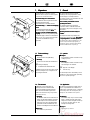 6
6
-
 7
7
-
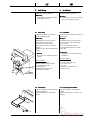 8
8
-
 9
9
-
 10
10
-
 11
11
-
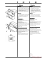 12
12
-
 13
13
-
 14
14
-
 15
15
-
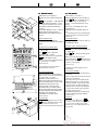 16
16
-
 17
17
-
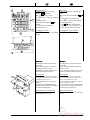 18
18
-
 19
19
-
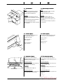 20
20
-
 21
21
-
 22
22
-
 23
23
-
 24
24
-
 25
25
-
 26
26
-
 27
27
-
 28
28
-
 29
29
-
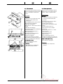 30
30
-
 31
31
-
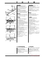 32
32
-
 33
33
-
 34
34
-
 35
35
-
 36
36
-
 37
37
-
 38
38
-
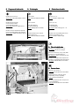 39
39
-
 40
40
-
 41
41


MBM MBM Triumph 5550 EP Manuel utilisateur
- Taper
- Manuel utilisateur
dans d''autres langues
- English: MBM MBM Triumph 5550 EP User manual
- español: MBM MBM Triumph 5550 EP Manual de usuario
- Deutsch: MBM MBM Triumph 5550 EP Benutzerhandbuch
- Nederlands: MBM MBM Triumph 5550 EP Handleiding