YORKVILLE NX55P Manuel utilisateur
- Catégorie
- Équipement musical supplémentaire
- Taper
- Manuel utilisateur

U.S.A.
Yorkville Sound Inc.
4625 Witmer Industrial Estate
Niagara Falls, New York
14305 USA
Voice: (716) 297-2920
Fax: (716) 297-3689
WORLD HEADQUARTERS
WEB ACCESS: http://www.yorkville.com
CANADA
Yorkville Sound
550 Granite Court
Pickering, Ontario
L1W-3Y8 CANADA
Voice: (905) 837-8481
Fax: (905) 837-8746
Quality and Innovation Since 1963
Printed in Canada
SERVICE MANUAL
NX55P
Manual-Service-NX55P-00-1v7 • Jul 16, 2009
TYPE: YS1002
Manual-Service-NX55P-REV2-00-3v4.pdf

The exclamation point within an equilatereal triangle is intended to alert the
user to the presence of important operating and maintenance (servicing)
instructions in the literature accompanying the appliance.
Le point d’exclamation à l’intérieur d’un triangle équilatéral est prévu pour alerter
l’utilisateur de la présence d’instructions importantes dans la littérature accompagnant
l’appareil en ce qui concerne l’opération et la maintenance de cet appareil.
This lightning flash with arrowhead symbol, within
an equilateral triangle, is intended to alert the user to the presence of
uninsulated “dangerous voltage” within the product’s enclosure that may be
of sufficient magnitude to constitute a risk of electric shock to persons.
Ce symbole d’éclair avec tête de flèche dans un triangle équilatéral est prévu pour alerter
l’utilisateur de la présence d’un « voltage dangereux » non-isolé à proximité de l’enceinte
du produit qui pourrait être d’ampleur suffisante pour présenter un risque de choque
_safety-5v0+UL60065-00-1v0 • October 28/2014
CAUTION: TO REDUCE THE RISK OF ELECTRIC SHOCK, DO NOT REMOVE COVER (OR BACK).
NO USER SERVICEABLE PARTS INSIDE.
REFER SERVICING TO QUALIFIED SERVICE PERSONNEL.
THIS DEVICE IS FOR INDOOR USE ONLY!
Instructions pertaining to a risk of fire, electric shock, or injury to a person
Read Instructions: The Owner’s Manual should be read and understood before operation of your unit. Please, save these
instructions for future reference and heed all warnings.
Clean only with dry cloth.
Packaging: Keep the box and packaging materials, in case the unit needs to be returned for service.
Warning: To reduce the risk or fire or electric shock, do not expose this apparatus to rain or moisture. Do not
use this apparatus near water!
Warning: When using electric products, basic precautions should always be followed, including the following:
Power Sources
Your unit should be connected to a power source only of the voltage specified in the owners manual or as marked on the
unit. This unit has a polarized plug. Do not use with an extension cord or receptacle unless the plug can be fully inserted.
Precautions should be taken so that the grounding scheme on the unit is not defeated. An apparatus with CLASS I
construction shall be connected to a Mains socket outlet with a protective earthing ground. Where the MAINS plug or an
appliance coupler is used as the disconnect device, the disconnect device shall remain readily operable.
Hazards
Do not place this product on an unstable cart, stand, tripod, bracket or table. The product may fall, causing serious personal
injury and serious damage to the product. Use only with cart, stand, tripod, bracket, or table recommended by the
manufacturer or sold with the product. Follow the manufacturer’s instructions when installing the product and use mounting
accessories recommended by the manufacturer. Only use attachments/accessories specified by the manufacturer
Note: Prolonged use of headphones at a high volume may cause health damage on your ears.
The apparatus should not be exposed to dripping or splashing water; no objects filled with liquids should be
placed on the apparatus.
Terminals marked with the “lightning bolt” are hazardous live; the external wiring connected to these terminals require
installation by an instructed person or the use of ready made leads or cords.
Ensure that proper ventilation is provided around the appliance. Do not install near any heat sources such as radiators,
heat registers, stoves, or other apparatus (including amplifiers) that produce heat.
No naked flame sources, such as lighted candles, should be placed on the apparatus.
Power Cord
Do not defeat the safety purpose of the polarized or grounding-type plug. A polarized plug has two blades with one wider than the
other. A grounding type plug has two blades and a third grounding prong. The wide blade or the third prong are provided for your
safety. If the provided plug does not fit into your outlet, consult an electrician for replacement of the obsolete outlet. The AC supply
cord should be routed so that it is unlikely that it will be damaged. Protect the power cord from being walked on or pinched particularly
at plugs. If the AC supply cord is damaged DO NOT OPERATE THE UNIT. To completely disconnect this apparatus from the AC
Mains, disconnect the power supply cord plug from the AC receptacle. The mains plug of the power supply cord shall remain readily
operable.
Unplug this apparatus during lightning storms or when unused for long periods of time.
Service
The unit should be serviced only by qualified service personnel. Servicing is required when the apparatus has been damaged in
any way, such as power-supply cord or plug is damaged, liquid has been spilled or objects have fallen into the apparatus, the
apparatus has been exposed to rain or moisture, does not operate normally, or has been dropped.
AVIS: AFIN DE REDUIRE LES RISQUE DE CHOC ELECTRIQUE, N’ENLEVEZ PAS LE COUVERT
(OU LE PANNEAU ARRIERE)
NE CONTIENT AUCUNE PIECE REPARABLE PAR L’UTILISATEUR.
CONSULTEZ UN TECHNICIEN QUALIFIE POUR L’ENTRETIENT
CE PRODUIT EST POUR L’USAGE À L’INTÉREUR SEULEMENT
Instructions relatives au risque de feu, choc électrique, ou blessures aux personnes
Veuillez Lire le Manuel: Il contient des informations qui devraient êtres comprises avant l’opération de votre appareil.
Conservez. Gardez S.V.P. ces instructions pour consultations ultérieures et observez tous les avertissements.
Nettoyez seulement avec le tissu sec.
Emballage: Conservez la boite au cas ou l’appareil devait être retourner pour réparation.
Avertissement: Pour réduire le risque de feu ou la décharge électrique, n'exposez pas cet appareil à la pluie ou à l'humidité.
N’utilisez pas cet appareil près de l’eau!
Attention: Lors de l’utilisation de produits électrique, assurez-vous d’adhérer à des précautions de bases incluant celle qui suivent:
Alimentation
L’appareil ne doit être branché qu’à une source d’alimentation correspondant au voltage spécifié dans le manuel ou tel
qu’indiqué sur l’appareil. Cet appareil est équipé d’une prise d’alimentation polarisée. Ne pas utiliser cet appareil avec un
cordon de raccordement à moins qu’il soit possible d’insérer complètement les trois lames. Des précautions doivent êtres
prises afin d’eviter que le système de mise à la terre de l’appareil ne soit désengagé. Un appareil construit selon les normes
de CLASS I devrait être raccordé à une prise murale d’alimentation avec connexion intacte de mise à la masse. Lorsqu’une
prise de branchement ou un coupleur d'appareils est utilisée comme dispositif de débranchement, ce dispositif de
débranchement devra demeurer pleinement fonctionnel avec raccordement à la masse.
Risque
Ne pas placer cet appareil sur un chariot, un support, un trépied ou une table instables. L’appareil pourrait tomber et blesser
quelqu’un ou subir des dommages importants. Utiliser seulement un chariot, un support, un trépied ou une table
recommandés par le fabricant ou vendus avec le produit. Suivre les instructions du fabricant pour installer l’appareil et utiliser
les accessoires recommandés par le fabricant. Utilisez seulement les attachements/accessoires indiqués par le fabricant
Note: L'utilisation prolongée des écouteurs à un volume élevé peut avoir des conséquences néfastes sur la santé
sur vos oreilles. .
Il convient de ne pas placer sur l’appareil de sources de flammes nues, telles que des bougies allumées.
L’appeil ne doit pas être exposé à des égouttements d’eau ou des éclaboussures et qu’aucun objet rempli de liquide tel
que des vases ne doit être placé sur l’appareil.
Assurez que lappareil est fourni de la propre ventilation. Ne procédez pas à l’installation près de source de chaleur tels
que radiateurs, registre de chaleur, fours ou autres appareils (incluant les amplificateurs) qui produisent de la chaleur.
Les dispositifs marqués d’une symbole “d’éclair” sont des parties dangereuses au toucher et que les câblages
extérieurs connectés à ces dispositifs de connection extérieure doivent être effectivés par un opérateur formé ou en
utilisant des cordons déjà préparés.
Cordon d’Alimentation
Ne pas enlever le dispositif de sécurité sur la prise polarisée ou la prise avec tige de mise à la masse du cordon d’alimentation.
Une prise polarisée dispose de deux lames dont une plus large que l’autre. Une prise avec tige de mise à la masse dispose de
deux lames en plus d’une troisième tige qui connecte à la masse. La lame plus large ou la tige de mise à la masse est prévu
pour votre sécurité. La prise murale est désuète si elle n’est pas conçue pour accepter ce type de prise avec dispositif de
sécurité. Dans ce cas, contactez un électricien pour faire remplacer la prise murale. Évitez d’endommager le cordon
d’alimentation. Protégez le cordon d’alimentation. Assurez-vous qu’on ne marche pas dessus et qu’on ne le pince pas en
particulier aux prises. N’UTILISEZ PAS L’APPAREIL si le cordon d’alimentation est endommagé. Pour débrancher
complètement cet appareil de l’alimentation CA principale, déconnectez le cordon d’alimentation de la prise d’alimentation
murale. Le cordon d’alimentation du bloc d’alimentation de l’appareil doit demeurer pleinement fonctionnel.
Débranchez cet appareil durant les orages ou si inutilisé pendant de longues périodes.
Service
Consultez un technicien qualifié pour l’entretien de votre appareil. L'entretien est nécessaire quand l'appareil a été endommagé de
quelque façon que se soit. Par exemple si le cordon d’alimentation ou la prise du cordon sont endommagés, si il y a eu du liquide
qui a été renversé à l’intérieur ou des objets sont tombés dans l'appareil, si l'appareil a été exposé à la pluie ou à l'humidité, si il ne
fonctionne pas normalement, ou a été échappé.
S2125A
Caution: hot surface
Attention: surface chaude
IEC 60417-5041
IMPORTANT SAFETY INSTRUCTIONS
IMPORTANT SAFETY INSTRUCTIONS (UL60065)
FOLLOW ALL INSTRUCTIONS SUIVEZ TOUTES LES INSTRUCTIONS
The Lightning Flash with arrowhead symbol within an equilateral triangle, is intended to alert the user to the presence of uninsulated
"dangerous voltage" within the product enclosure that may be of sufficient magnitude to constitute a risk of shock to persons
The exclamation point within an equilateral triangle is intended to alert the user to the presence of important operating and maintenance
(servicing) instructions in the literature accompanying the product
1. Read these instructions.
2. Keep these instructions.
3. Heed all warnings.
4. Follow all instructions.
5. Do not use this apparatus near water.
6. Clean only with dry cloth.
7. Do not block any ventilation openings. Install in accordance with the manufacturer’s instructions.
8. Do not install near any heat sources such as radiators, heat registers, stoves, or other apparatus (including amplifiers) that produce heat.
9. Do not defeat the safety purpose of the polarized or grounding-type plug. A polarized plug has two blades with one wider than the other. A
grounding type plug has two blades and a third grounding prong. The wide blade or the third prongs are provided for your safety. If the provided
plug does not fit into your outlet, consult an electrician for replacement of the obsolete outlet.
10. Protect the power cord from being walked on or pinched particularly at plugs, convenience receptacles, and the point where they exit
from the apparatus.
11. Only use attachments/accessories specified by the manufacturer.
12. Use only with the cart, stand, tripod, bracket, or table specified by the manufacturer, or sold with the apparatus. When a cart is used, use caution
when moving the cart/apparatus combination to avoid injury from tip-over.
13. Unplug this apparatus during lightning storms or when unused for long periods of time.
14. Refer all servicing to qualified service personnel. Servicing is required when the apparatus has been damaged in any way, such as
power-supply cord or plug is damaged, liquid has been spilled or objects have fallen into the apparatus, the apparatus has been exposed to rain or
moisture, does not operate normally, or has been dropped.
WARNING:
• To reduce the risk of fire or electric shock, do not expose this apparatus to rain or moisture and objects filled with liquids, such as vases, should not be
placed on this apparatus.
• To completely disconnect this apparatus from the ac mains, disconnect the power supply cord plug from the ac receptacle.
• The mains plug of the power supply cord or appliance coupler shall remain readily accessible.
Le symbole représentant un éclair avec une flèche à l’intérieur d’un triangle équilatéral est utilisé pour prévenir l’utilisateur de la
présence d’une tension électrique dangereuse non isolée à l’intérieur de l’appareil. Cette tension est d’un niveau suffisamment
élevé pour représenter un risque d’électrocution
Le symbole représentant un point d’exclamation à l’intérieur d’un triangle équilatéral, signale à l’utilisateur la présence d’instructions
importantes relatives au fonctionnement et à l’entretien de l’appareil dans cette notice d’installation
1. Lisez ces instructions.
2. Conservez ces instructions.
3. Respecter tous les avertissements.
4. Suivez toutes les instructions.
5. N'utilisez pas l'appareil près de l'eau.
6. Nettoyer uniquement avec chiffon sec.
7. Ne bloquez pas les ouvertures de ventilation. Installer en suivant les instructions du fabricant.
8. Ne pas installer près des sources de chaleur telles que radiateurs, bouches de chaleur, four ou autres appareils (y compris les amplificateurs)
produisant de la chaleur.
9. N'annulez pas l'objectif sécuritaire de la fiche polarisée ou de la tige de mise à la terre. Une fiche polarisée possède deux lames avec une plus
large que l'autre. Une prise avec mise à la terre possède deux lames et une troisième tige. La lame large ou la troisième tige sont fournis pour
votre sécurité. Si la fiche n'entre pas dans votre prise, consultez un électricien pour remplacer la prise obsolète.
10. Protéger le cordon d'alimentation des piétinements ou pincements en particulier près des fiches, des prises de courant et au point de
sortie de l'appareil.
11. Utilisez uniquement les accessoires spécifiés par le fabricant.
12. Utiliser uniquement avec un charriot, stand, trépied ou une table spécifiée par le fabricant, ou vendus avec l'appareil.
13. Débranchez l'appareil durant un orage ou lorsqu'il reste inutilisé pendant de longues périodes de temps.
14. Confiez toute réparation à un technicien qualifié. Une réparation est nécessaire lorsque l'appareil a été endommagé de quelque façon que ce
soit; comme lorsque le cordon d'alimentation ou la fiche est endommagé, lorsque du liquide a été renversé ou des objets sont tombés à l'intérieur,
lorsque l'appareil a été exposé à la pluie ou l'humidité, ne fonctionne pas normalement, ou est tombé.
AVERTISSEMENT:
• Pour réduire les risques d'incendie ou de choc électrique, ne pas exposer cet appareil à la pluie ou à l'humidité et ne placez pas d’objets contenant
des liquides, tels que des vases, sur l’appareil.
• Pour isoler totalement cet appareil de l'alimentation secteur, débranchez totalement son cordon d'alimentation du réceptacle CA.
• La prise du cordon d’alimentation ou du prolongateur, si vous en utilisez un comme dispositif de débranchement, doit rester facilement accessible
CAUTION
TO PREVENT ELECTRIC SHOCK HAZARD,
DO NOT CONNECT TO MAINS POWER SUPPLY
WHILE GRILLE IS REMOVED.
AVIS
POUR PRÉVENIR LES RISQUES D'ÉLECTROCUTION,
NE PAS RACCORDER A L’ALIMENTATION ÉLECTRIQUE ALORS
QUE LA GRILLE EST RETIRÉE.

1
SERVICE BULLETIN
IMPORTANT SERVICE NOTICE!
NX55P and NX750P
M1309V06 and newer version circuit boards are NOT backwards
compatible with ANY previous versions of M1309 boards!
Note: Due to ongoing changes in the layout of the power sup-
ply and the power amplifier, the circuit board M1309V06 (Ver-
sion 06) and newer versions are not compatible with board
M1309V05 (version 05) or previous versions, the pin-outs on the
connectors have been re-arranged.
If you need to change one of the older versions of the circuit
boards with the new one you MUST change BOTH amplifier and
power supply boards!
DO NOT mix different version circuit boards!
AVIS IMPORTANT DE SERVICE !
NX55P et NX750P
Les nouvelles versions du circuit imprimé M1309 en commençant par
la version M1309V06 ne sont pas rétro-compatible avec les versions
précédentes du circuit !
Remarque : En raison des changements continus dans
l'agencement de la section de l’alimentation et de l’amplificateur
de puissance, le circuit imprimé M1309V06 (version 06) et les
versions plus récentes sont pas compatible avec le circuit im-
primé M1309V05 (version 05) ou les versions antérieures, les
brochages des connecteurs ont été réarrangés.
Si vous devez remplacer une ancienne version de circuit imprimé par
une nouvelle version, vous DEVEZ changer les DEUX circuits, soit
celui de l’amplificateur et celui de l'alimentation
Direct Link: NX55P Service Manual M1309V06 and newer
Direct Link: NX55P Service Manual M1309V05 and older
Direct Link: NX750P Service Manual M1309V06 and newer
Direct Link: NX750P Service Manual M1309V05 and older
SERVICE-BULLETIN-NX55P-NX750P-00-1v1 • Aug 8, 2011

MIC
INPUTOUTPUT
A-Z822 / 1v0
MIXER
CLIP
LIMIT
MIC
100
BASS
1212
dB
TREBLE
12
12
dB
LINE/CD
100
dB
NX55P
LEVEL
6
00
LF ROLLOFF
0
100Hz60Hz
MIXER
OFF
ON
PWR
CAUTION: REPLACE WITH
SAME TYPE FUSE AND RATING
ATTENTION: UTILISER UN FUSIBLE DE
RECHANGE DE MEME TYPE ET CALIBRE
P
550 WATT POWERED LOUDSPEAKER ENCLOSURE
NOTES:
ALL LINK CONNECTIONS FUNCTION AS
INPUTS OR OUTPUTS.
EXTERNAL MIXERS CONNECT TO LINK INPUTS
Designed & Manufactured by
YORKVILLE SOUND • TORONTO, CANADA
POWER
FUSE
ONOFF
LINK
Yorkville
1
3
2
1
3
2
2
3
1
+24 PHANTOM
MIC
LINE / CD LEVEL
MIC LEVEL
LINE / CD
MIXER ON / OFF
NX55P LEVEL
Yorkville
230V
50Hz 1,0A
FUSE: F3,15A 250V
FUSE: 4.0A 250V
FastBlo
120VAC 60Hz 2.0A
MODEL TYPE: YS1002
A-Z823 / 1v5
LINE / CD
INPUTOUTPUT
BAL
LINK

ON/OFF
BLOCK-DIAG-NX55P-00-2v0.ai
CLIP DETECT
CIRCUIT
INPUT
DIFF AMP
INTEGRATED
ERROR AMP
RAMP
GENERATOR
GND AT
OUTPUT
U9. Q8, U10
LEVEL SHIFT
U6
GATE DRIVE
MONO
SUM
BUFFERS
100 Hz 60 Hz
1
2
3
-120
U7
100 Hz
LIMITER
LED
60 Hz
HF DRIVER
WOOFER
WOOFER
OUTPUT
TRANSISTORS
OUTPUT
FILTER
MODEL TYPE:YS1002
HP
HP
60 Hz
BYPASS
LP
LP
EQ
LP LP
R47
+24 PHANTOM
1
3
2
LINK
1
3
2
2
3
1
LIMIT
LIMIT
LIMIT
2-TIER
LINEAR AMP
(HORN)
CLASS-D
AMPLIFIER
(WOOFER)
*CLASS-D AMPLIFIER (WOOFER)
*BLOCK DIAGRAM
LOCATED BELOW
NOTE: Shorting R47 will eliminate
feedback and audio signal allowing
troubleshooting of Level Shift, drivers
and output devices
LIMIT DETECT SLOW
LIMIT DETECT FAST
MIC
LINE / CD LEVEL
MIC LEVEL
LINE / CD
SILENT ON/OFF
RELAY
SILENT ON/OFF
RELAY
SILENT ON/OFF
VIA Q19
SILENT ON/OFF
RELAY
Tone
EQ (2 NOTCHES)
MIXER
Block Diagram for NX55P
D E S I G N E D & M A N U FA
C T U R E D B Y Y O R K V I L L E S O U N D

Specifications
System Type
2-Way
Active or Passive
Active
Program Power (Watts)
550
Biampable
Self Powered
Biamp Operation Only
Yes
Max SPL (dB)
124
Frequency Response (Hz +/- 3db)
45 - 18k
Crossover Frequency (Hz)
2300
Driver Configuration
12 inch / 1 inch
HF Driver(s)
1 inch Throat, Ceramic Magnet, 1 inch Mylar voicecoil
HF Program Power (Watts)
100
HF Dispersion (°H x °V)
80 x 50
LF Driver(s)
12 inch Neodymium Magnet 3 inch voicecoil
LF Program Power(Watts)
450
Total Power (Watts)
550
HF Amplifier Type
Two Tier Class H
LF Amplifier Type
Class D
Power Cable
Yes
Power Switch
Yes
Inputs
7
Inputs - 1/4" Jacks
2 (line input) 2 (link in/out)
Inputs - XLR
1 (mic) 2 (line in/out)
Input Sensitivity (Vrms Sine)
+4dBv / 1.23V
Mixer on/off switch
Mic Gain
Line/CD Gain
Treble/Bass Tweak
Level Controls
+/- 6dB Main Volume
EQ Controls
100Hz HP Filter (LF Rolloff)
Limiter
Yes
LED Indicators
Power/Clip/Limit
Feet
Yes
Flying Hardware
2 (Top), 2 (Bottom), 1 (Pullback)
Optional Flying Hardware
NX Flyware
Bar Handles
1 (Side)
Pole Mount Adapter (1 3/8"-3.5cm)
Yes
Enclosure Materials
Injection molded Polypropylene
Grille
Perforated Metal
Dimensions (DWH xbackW, inches)
12.25 x 16 x 26.5 x 9
Dimensions (DWH xbackW, cm)
31.12 x 40.6 x 67.3 x 22.9
Weight (lbs/kg)
41 / 18.6
Mixer Controls

Product
Date:
Filename:
PCB# ofSheet
Rev:
31
V08
M1309V08SCH.sch2006
NX55P
Fri Jun 28, 2013
M1309NX55P
A
-15V
+15V
-15V
HLIM
IGND
+15V
-15V
4148
D46
1/4W
2K
R102
RAD
+15V
+15V
-15V
W5:B
6
W28:A
4
W28:C
4
W28:D
4
-15V
-15V
4148
D44
+15V
-15V
+15V
WLIM
LVGND2
+15V
+15V
IGND
LVGND2
C83
63V470N
+15V
R225
1/4W
RAD
3K3
R119
1/4W
MINI
100K
C64
100V47N
4148
D35
LEDGND
4148
D25
1/4W
MINI
56K
R165
+15V
non-RoHS
-15V
LVGND2
R131
1/4W
RAD
2K7
LVGND1
-15V
1/4W
.
2M2
R231
1/4W
RAD
10K
R232
R104
1/4W
0.1%
681R0
R186
NET00306
NET00281
NET00274
+15V
-15V
+15V
NET00295
NET00127
HORNGND
-15V
R233
1/4W
MINI
1K0
IGND
4010
J2
{Function}
1
2
3
4100
J1
R113
1/8W
FLMP
475R
1/4W
1M
R108
RAD
R93
1/8W
FLMP
475R
B
R114
1/4W
RAD
10K
C76
100V100N
C65
100V100N
+15V
-15V
R94
1/4W
RAD
10K
UP DOWN
S3:B
3522
SUB IN/OUT
4148
D42
R126
1/4W
MINI
4K99
R234
1/4W
MINI
1K0
R92
1/4W
0.1%
681R0
U36:B
NE5532N
-15V
R223
1/4W
MINI
3K
1/4W
RAD
27K
R151
330N 63V
C113
100V
C86
47N
U17:A
NE5532N
100P 100V
C153
1/4W
MINI
22K
R87
4148
D45
1/4W
MINI
15K
R228
R127
1/4W
RAD
470R
4148
D31
TO92
MPSA13
Q21
5105
1/4W
1K5
R107
RAD
L2
RED
5906
CLIP
8
V+
4
V-
U18:C
-15V
1/4W
2K
R226
RAD
1/4W
5K1
R138
RAD
1/4W
1K
R91
RAD
LVGND1
+15V
W5:C
6
W5:A
6
1/4W
MINI
15K
R158
1/4W
3K3
R227
RAD
W28:B
4
R141
1/4W
MINI
150R
4
3
NSL-32SR2
U15:B
6858
R152
1/4W
MINI
2K
TO M1339
LIMITER
BOARD
(RoHS)
HLIM
W5:F
6
W5:E
6
W5:D
6
BAV21
D36
+15V
1/4W
249R
R142
.
NET00011
LVGND1
R96
1/4W
0.1%
681R0
1/4W
249R
R100
.
-15V
U14:A
NE5532N
1/4W
RAD
470R
R230
BAV21
D41
1/4W
3K3
R229
RAD
1/4W
4K3
R145
.
C69
100V47N
+15V
C59
100V47N
330N 63V
C136
C79
63V220N
WOOFCLIP
LVGND1
R140
1/4W
RAD
10K
4148
D37
R118
1/4W
RAD
27K
4148
D27
100V
C61
47N
Q23
5108
TO92
2N5401
LVGND2
1/4W
15K
R137
MINI
R125
1/4W
MINI
4K99
D39
0A2 BAT85
BAT85
D40
0A2
R117
1/4W
MINI
10K0
C145
100V33N
1/4W
4K7
R159
RAD
R214
1/4W
RAD
470R
WOOFER
LIMITER
CONTROL
1/4W
470R
R124
MINI
8
V+
4
V-
U27:C
U27:B
NE5532N
NET00290
NET00135
non-RoHS
WLIM
BAT85
D43
LVGND
1/4W
1K21
R101
MINI
1/4W
2K
R146
RAD
1/4W
R86
1K0
MINI
1/4W
6K19
R143
MINI
8
V+
4
V-
U22:C
LVGND1
R123
1/4W
MINI
470R
R222
1/4W
MINI
47K
BAT85
D34
R85
1/4W
MINI
1K21
NET00117
U35:E
1/4W
1K5
R153
RAD
L3
YEL
5907
LIMIT
TO POWER AMP PCB
LVGND
100V
C150
68N
1/4W
1M
R103
RAD
1/4W
10K
R109
RAD
1/4W
18K
R149
RAD
U24:A
NE5532N
R110
1/4W
0.1%
681R0
C151
63V150N
R133
1/4W
MINI
1K0
1/4W
R208
100R
RAD
R134
1/4W
MINI
1K0
R224
1/4W
MINI
3K
1/4W
MINI
4K99
R155
LVGND2
8
V+
4
V-
U25:C
250V
C66
4N7
8
V+
4
V-
U14:C
+15V
1/4W
MINI
15K
R161
+15V
R121
1/4W
RAD
12K
8
V+
4
V-
U13:C
U22:A
TL072
4148
D62
1/4W
15K
R156
MINI
C88
63V2U2
R97
1/4W
MINI
1K8
R122
1/4W
MINI
10K0
U19:B
NE5532N
R90
1/4W
MINI
270R
C23
16V
33U
U20:A
NE5532N
1/4W
47K
R154
RAD
4148
D38
6V2
0W5
1N753ARL
D33
1/4W
33K
R89
MINI
1
2
NSL-32SR2
U23:A
6858
8
V+
4
V-
U20:C
100V
C70
100N
R99
1/4W
MINI
1K0
1/4W
1K0
R130
MINI
+15V
TO92
MPSA06
Q22
5103
LEDGND
8
V+
4
V-
U12:C
C82
63V470N
C62
100V100P
47P 100V
C154
C75
100V47N
R88
1/4W
MINI
1K0
1/4W
MINI
1K2
R183
1/4W
RAD
2K
R135
-15V
R115
1/4W
RAD
1M
BOOST
C60
100V10N
NET00136
D32
0A2 BAT85
D29
0A2 BAT85
LVGND1
C146
100V68N
non-RoHS
+15V
4
9
W4:D
3
9
W4:C
2
9
W4:B
1
9
W4:A
+15V
-15V
U36:A
NE5532N
R235
1/4W
MINI
1K0
R162
1/4W
MINI
1K0
4148
D30
R111
1/4W
0.1%
562R0
C73
100V100P
4148
D26
8
V+
4
V-
U17:C
100V
C72
470P
FROM MIXER
R95
1/4W
0.1%
562R0
8
V+
4
V-
U16:C
U16:B
NE5532N
MAIN INPUT
LVGND2
1/4W
MINI
56K
R150
330N 63V
C100
1/4W
MINI
1K21
R129
C78
63V150N
100V
C74
100N
R120
1/4W
RAD
18K
MASTER CLIP
M
P1:A
4434
10K
B
MASTER_GAIN
U18:B
NE5532N
BOOST/ LIMITER
BAV21
D28
U26:A
NE5532N
non-RoHS
R136
1/4W
0.1%
681R0
R112
1/4W
MINI
1K8
C85
63V150N
X2
8
V+
4
V-
U21:C
U21:B
NE5532N
NET00011
TO M1339
LIMITER
BOARD
(RoHS)
R139
1/4W
RAD
33K
C90
100V22N
C68
100V68N
1/4W
1K8
R106
MINI
1/4W
6K04
R84
.
2K5 NOTCH
(VCC)
LM13600N
Dual VCA
6745
U35:D
C80
63V470N
U22:B
TL072
RMS LIMITER
LVGND2
U21:A
NE5532N
LIMITER
63V
C30
100N
U12:A
NE5532N
3K9 NOTCH
U13:B
NE5532N
R144
1/4W
MINI
270R
NET00150
(VCC)
LM13600N
Dual VCA
6745
U35:C
1/4W
47K
R163
RAD
LIMITER SENSE
1/4W
R157
3K3
RAD
1
2
NSL-32SR2
U15:A
6858
HORN
LIMITER
CONTROL
LVGND2
8
9
W4:H
9
9
W4:I
+24V
-15V
5
9
W4:E
6
9
W4:F
7
9
W4:G
1/4W
15K
R148
MINI
C149
63V150N
100V
C152
68N
8
V+
4
V-
U36:C
100V
C67
470P
U16:A
NE5532N
LM13600N
U35:A
8
V+
4
V-
U24:C
U24:B
NE5532N
TRIM
/GAIN
8
V+
4
V-
U26:C
U26:B
NE5532N
R132
1/4W
MINI
15K
4
3
NSL-32SR2
U23:B
6858
C87
50V22U
U19:A
NE5532N
8
V+
4
V-
U19:C
U14:B
NE5532N
100V
C93
15N
LVGND1
U13:A
NE5532N
1/4W
56K
R128
.
U20:B
NE5532N
C19
10U
16V
1/4W
100R
R116
RAD
WOOFCLIP
LM13600N
U35:B
U25:A
NE5532N
3522
S3:A
UP DOWN
SUB IN/OUT
U27:A
NE5532N
U17:B
NE5532N
U18:A
NE5532N
NOTCH FILTER VALUES FOR
YS#7527 COMPRESSION DRIVER.
RING
J3
RING
J7
U25:B
NE5532N
U12:B
NE5532N

Product
Date:
Filename:
PCB# ofSheet
Rev:
32
V08
M1309V08SCH.sch2006
NX55P
Fri Jun 28, 2013
M1309NX55P
-15V_C
TP2
-44V
-15V
-15V
+15V
+15V_C
-15V
-120V
1/4W
1K4
R70
.
1/4W
1K4
R63
.
1/4W
2K2
R16
MINI
+
1/2W
150K
R48
.
1/4W
2K2
R24
MINI
+44V
FROM POWER SUPPLY
+15V
1/4W
1K4
R74
.
1/4W
1K0
R66
MINI
+24V
LVGND
SILENT
+44V
-22V
4
W2:D 0
+22V
+120V
PSGND
8
W2:H 0
-15V_C
+/-15V_C
7
W1:G9
6
W1:F9
3
W1:C9
2
W1:B9
1
W1:A9
+44V
-15V
PSGND
-15V_MOD
-15V_MOD
PSGND
SILENT
+15V_MOD
R20
1/4W
RAD
1M
R13
1/4W
MINI
2K2
WOOFGND
D19
0A2 BAT85
+15V_LS
R14
1/4W
RAD
18K
NET00095
NET00094
R23
1/4W
FUSIBLE
11R
TP1
1N5246B 16V0
D2 0W5
-22V
MR854
D10
PSGND
HORNGND
NET00091
NET00090
NET00093
NET00058
100V
C91
100N
5.0W
12K
R105
.
+15V
-44V
2
W2:B 0
1
W2:A 0
3
W2:C 0
-120V
6
W2:F 0
7
W2:G 0
5
W2:E 0
R44
1/8W
FLMP
10R0
5
W1:E9
9
W1:I9
8
W1:H9
4
W1:D9
1N5254B
D4
0W5
27V0
LVGND
1/4W
4K7
R10
RAD
100V
100N
C58
100V
C50
100N
+15V
R56
1/4W
MINI
6K8
R51
1/4W
MINI
6K8
+24V
100V
C56
100N
100V
C55
100N
100V
C48
100N
100V
C47
100N
+15V_MOD
R73
1/8W
FLMP
10R0
100V
C44
100N
100V
C41
100N
R64
1/8W
FLMP
10R0
WOOFGND
-15V_MOD
1/4W
6K8
R59
MINI
R45
1/4W
MINI
6K8
C28
100V470P
+15V_MOD
U2:B
MC33078P
8
V+
4
V-
U2:C
C18
100V220P
100V
C57
100N
PSGND
100V
C49
100N
+4V7_LS
PSGND
+15V_LS
5.0W
8K2
R75
.
R54
1/4W
MINI
1K0
R36
1/8W
FLMP
100R0
100V
C43
100N
5.0W
8K2
R67
.
5.0W
8K2
R68
.
5.0W
8K2
R69
.
100V
C17
100N
-120V
63V
470N
C143
+4V7_LS
WOOFGND
1N750ARL
D18
0W5
4V7
-15V_MOD
C29
100V10N
R47
1/4W
RAD
1M
WOOFGND
1N750ARL
D12
0W5
4V7
LVGND
4148
D5
WOOFGND -120V
+5V_MOD +4V7_LS
-120V
3
IN
4
OUT
U9:B
74HC14N
6603
-15V_MOD
1/4W
2K2
R212
MINI
100V
C16
100N
WOOFGND
1/4W
22K
R40
MINI
7
GND
14
V+
U3:C
6964
100V
C8
680P
100V
C46
470P
1/4W
220R
R221
MINI
-120V
TO92
BC560C
Q5
5102
TO92
2N5401
Q7
5108
100V
C38
3N3
1/4W
47K
R166
MINI
-120V
1/4W
100K
R25
RAD
TO92
2N5401
Q8
5108
1/4W
3K9
R5
.
R219
1/4W
RAD
470R
HORNGND
+4V7_LS
R72
1/4W
RAD
82K
C142
100V100N
TO92
2N5551
Q17
5107
100V
C34
100N
63V
C35
1U
1/2W
1R
R46
SMALL
D15
0A2 BAT85
R37
1/4W
MINI
150R
25V
C4
68U
R1
1/4W
MINI
22K
1/4W
180K
R71
MINI
-15V_MOD
1N5248B
D20
0W5
18V0
1/4W
1M
R57
RAD
1/4W
1M
R41
RAD
TO92
MPSA92
Q13
5114
1/4W
680R
R7
RAD
1/4W
10K
R8
RAD
1/4W
2K2
R9
MINI
NET00096
1/8W
1K5
R60
FLMP
-120V
5.0W
0R047
R58
.
NET00216
5.0W
0R047
R31
.
1/8W
1K5
R33
FLMP
+120V
D11
0W5
12V0
1N5242B
R6
1/4W
FUSIBLE
11R
D1
0W5
12V0
1N5242B
1N5246B 16V0
D90W5
1.0W
0R47
R17
FLMP
1.0W
0R47
R18
FLMP
+22V
MR854
D3
+4V7_LS
WOOFGND
400V
C118
2N2
NET00092
NET00052
NET00002
100V
C71
680P
HORNGND
R38
1/8W
FLMP
10R0
TO92
2N5551
Q4
5107
R34
1/4W
MINI
47K
63V
C32
220N
4148
D14
OUTIN
GND
MC78L05ABPRM
6728
U11
TO92
{Function}
100V
C42
100N
R42
1/4W
MINI
2K
1N5251BRL 22V0
D8 0W5
1/4W
10K
R22
RAD
TO92
2N5401
Q18
5108
9
IN
8
OUT
U9:D
74HC14N
6603
7 14
1/4W
2K74
R213
0.1%
1/4W
22K
R32
MINI
R80
1/4W
0.1%
4K12
1/4W
R76
4K12
0.1%
1/4W
4K7
R49
MINI
U3:A6964
R77
1/4W
.
37K4
100V
C45
470P
R81
1/4W
.
37K4
100V
C33
100N
U3:B6964
+5V_MOD
R147
0.6W
SMALL
18k7
63V
C3
4U7
1/4W
4K7
R62
RAD
100V
C24
100N
4148
D6
C6
500V10P
63V
C9
4U7
2.0W
2K2
R3
.
1/4W
270R
R15
RAD
NET00206
100V
C5
100N
100V
C14
680P
100V
C15
220P
340V
C51
3U3
1.0W
0R47
R11
FLMP
140V
C20
3U3
140V
C31
3U3
140V
C22
3U3
1.0W
0R47
R12
FLMP
1/4W
6R2
R220
.
#7455
12" 4R
450WPGM
#7461
1" 8R
40W
-15V_MOD
+15V_MOD
HORNGND
+5V_MOD
WOOFGND
WOOFGND
-15V_MOD
+15V_MOD
R19
1/4W
MINI
2K2
+4V7_LS
C92
100V3N3
5 NEG-WOOFER
BLK
3
HORN-POS
YEL
100V
C53
100N
LVGND
+/-15V_MOD
U6:B
MC33079P
100V
C37
470P
100V
C21
100N
100V
C54
100N
R79
1/4W
MINI
1K0
+5V_MOD
1/8W
100R0
R83
FLMP
1
IN
2
OUT
U10:A
74HC14N
6603
D23
4V7
0W5
1N750ARL
1
IN
2
OUT
U9:A
74HC14N
6603
R52
1/4W
.
1K4
U6:C
MC33079P
100V
C36
47N
+15V_MOD
R55
1/4W
MINI
1K0
100V
C27
100N
R43
1/4W
MINI
47R
-15V_MOD
R35
1/8W
FLMP
100R0
U2:A
MC33078P
-15V_MOD
2
+
3
-
4
V-
8
V+
5
BAL
1
GND
7
OUT
6
STROBE
LM311
U1
6640
+15V_MOD
1/4W
2K
R30
MINI
100V
C52
100N
R28
1/4W
MINI
4K7
HORNGND
SILENT ON/OFF
TO92
Q9
5119
2N5638
WOOFGND
4148
D24
5
IN
6
OUT
U10:C
74HC14N
6603
R65
1/4W
MINI
1K0
R53
1/4W
.
6R2
+4V7_LS
10
9
8
U5:C
74HC86N
6605
4
5
6
U5:B
74HC86N
6605
UF4004
D17
+4V7_LS
-120V
R39
1/4W
.
2R2
4148
D21
TO92
BC560C
Q6
5102
1/4W
18K
R21
MINI
1N5242B
D7
0W5
12V0
C144
100V10N
R4
2.0W
.
2K2
6887
U8:B
TO92
Q20
5119
2N5638
SILENT ON/OFF
L13786
233UH
1N5248B
D16
0W5
18V0
R26
1/4W
FLMP
2K21
63V
C13
10U
6873_S
Q11
MJE340
TO126
DS
G
P
IRFP9140N
Q1:A
6932
TO247
BDX53C
6912
Q2
TO220
R2
1/4W
FLMP
2K21
6
POS-WOOFER
RED
4
HORN-NEG
BLK
4
V+
11
V-
U6:E
WOOFGND
100V
C26
100N
63V
C7
10U
FROM INPUT PCB
PHANTOM SUPPLY
WOOFGND
7 14
D22
0W5
10V0
1N5240BRL
2
+
3
-
4
V-
8
V+
5
BAL
1
GND
7
OUT
6
STROBE
LM311
U7
6640
2
+
3
-
4
V-
8
V+
5
BAL
1
GND
7
OUT
6
STROBE
LM311
U4
6640
U6:A
MC33079P
63V
C12
1U
63V
C11
2U2
TO92
MPSA92
Q19
5114
R82
1/4W
.
37K4
R78
0.6W
SMALL
18k7
WOOFER AMP
63V
C25
1U
13
12
11
U5:D
74HC86N
6605
1
2
3
U5:A
74HC86N
6605
250V
C141
4N7
U8:A
6887
IR2110
R50
1/8W
FLMP
75R
100V
C10
15P
100V
C39
5N6
G
D
S
IRFP23N50L
N
Q14:A
6967
TO247
G
D
S
IRFP23N50L
N
Q15:A
6967
TO247
TO92
BC550C
Q3
5101
1/4W
100R
R27
RAD
BDX54C
6911
Q10
TO220
1/4W
1K0
R29
MINI
100V
C1
680P
63V
C2
10U
G
D
S
IRFP140N
N
Q12:A
6931
TO247
WOOFER
S2
S1
HORN
14
V+
7
V-
U5:E
11
IN
10
OUT
U10:E
74HC14N
6603
U6:D
MC33079P
9
IN
8
OUT
U10:D
74HC14N
6603
13
IN
12
OUT
U9:F
74HC14N
6603
5
IN
6
OUT
U9:C
74HC14N
6603
13
IN
12
OUT
U10:F
74HC14N
6603
3
IN
4
OUT
U10:B
74HC14N
6603
11
IN
10
OUT
U9:E
74HC14N
6603
HORN AMP

Product
Date:
Filename:
PCB# ofSheet
Rev:
33
V08
M1309V08SCH.sch2006
NX55P
Fri Jun 28, 2013
M1309NX55P
-15V
PSGND
BLU
BLK
IGND
+15V
WHT
BRN
4007
D49
B
4007
D50
NET00299
+22V
VIO
A
NET00300
+15V
GRN
YEL
-22V
C98
50V 22U
R173
1/8W
FLMP
249R
IGND
+15V
3392
W21 AC WHT
C95
100V100N
1
6 W32:A
4
6 W32:D
2
6 W34:B
5
6 W34:E
+15V
VIO
GRY
RED
YEL/BLK
YEL
RED
GRY
VIO
+15V
LVGND4
7.0 AMP SLO-BLO
-15V
NET00303
1
8 W12:A
PSGND
-44V
+44V
MR752
D48
-120V
RED
BLK
7
8 W12:G
IGND
IGND
4010
J4
{Function}
R209
1/4W
MINI
10K0
R205
1/4W
MINI
10K0
R196
1/4W
MINI
10K0
R189
1/4W
MINI
10K0
C107
50V 22U
R181
1/8W
FLMP
249R
C94
50V 22U
R168
1/4W
MINI
220R
R203
1/4W
MINI
1K0
50V
C138
33P
R190
1/4W
MINI
1K0
50V
C129
33P
LVGND3
-15V
LVGND3IGND
R191
1/4W
MINI
10K0
C99
16V
33U
R172
1/4W
MINI
1K0
IGND
W16
INPUT GND
BLK
1.0W
1K8
R187
.
W36
S4
DPDT Switch
1/4W
47K
R197
RAD
R177
1/4W
MINI
18K
1300UH
L56492
3392
W9
AC BLK
LINE GAIN
1/8W
75R
R201
FLMP
C128
16V
33U
1/4W
30K
R179
RAD
R169
1/4W
MINI
6K8
6
6 W32:F
5
6 W32:E
1
6 W34:A
120V
3
6 W34:C
4
6 W34:D
6
6 W34:F
-15V
R180
1/4W
RAD
2K
R206
1/4W
RAD
220R
-15V
100V
C131
100N
3
2
1
R210
1/4W
MINI
1K2
100V
C133
100N
50V
C132
100N
1/4W
47K
R204
MINI
100V
C135
100N
#2410
F4A
R61
T7.0
2487
7.0 AMP SLO-BLO
LVGND4
100V
C137
100N
LVGND
#2470
F2A
CE
50V
C111
2200U
SILENT
5
8 W12:E
ORN
+15V
#2410
F4A
N.A.
63V
C110
4U7
+15V
LVGND4
K1:B
1N5250B 20V0
D130W5
#2482
F3.15A
CE
CH1254U
1N5402
D60
1N5402
D57
1N5402
D51
63V
C115
2200U
3
8 W12:C
MR752
D61
MR752
D53
6
8 W12:F
PSGND
8
8 W12:H
+120V
BRN
1/4W
2K49
R185
MINI
R174
1/4W
0.1%
562R0
R182
1/4W
0.1%
562R0
8
V+
4
V-
U32:C
M
B
P2:A
4432
10K
MIC_GAIN
C97
16V
33U
IG
TO-220
O
78XX
240V
2
6 W32:B
3
6 W32:C
1/4W
1K
R184
RAD
1/4W
10K
R188
RAD
100V
C119
100N
LVGND1
2
3
4
1
R192
1/4W
RAD
4K7
100V
C121
100N
50V
C120
100N
R98
T7.0
2487
100V
C125
100N
R194
1/4W
.
332R0
4
8W12:D
UP
S5:A
3522
DOWN
MIXER IN/OUT
50V
C105
2200U
100V
C109
100N
1/4W
1K07
R176
0.1%
-15V
OUTIN
GND
MC7915CT
6871 {Watts}
U31
TO220
1/4W
1K4
R202
.
63V
C103
4U7
OUTIN
GND
MC7815CT
6872 {Watts}
U30
TO220
4148
D63
1N5402
D54
2
8 W12:B
BLU
63V
C104
2200U
MR752
D59
CB
TO-126
MJE350
MJE340
BD238
MJE270
BD139
BD140
E
BD237
MJE271
BC
TO-92
MPSA63
MPSA43
2N5551
E
MPSA56
MPSA06
MPSA13
2N5401
W8
C96
100V68N
-15V
4
4W33:D
1
4W33:A
LVGND3
IEC_RECT
LVGND4
C126
16V 33U
8
V+
4
V-
U28:C
U28:A
NE5532N
1/8W
75R
R178
FLMP
50V
C108
1N
R171
1/4W
RAD
47K
R170
1/4W
MINI
10K0
+24V
R167
1/4W
MINI
10K0
100V
C40
100N
250V
4N7
C112
FUSE
F1
FAST BLOW
FUSE
N.A.: #2410 F 4A
CE: #2470 F2A
R195
1/4W
RAD
10K
R200
1/4W
RAD
10K
R199
1/4W
MINI
1K0
R160
1/4W
RAD
4K7
U29:A
NE5532N
+15V
FUSE F1
N.A.
TRANSFORMER CH1254U
1N5402
D58
1N5402
D56
2
3W31:B
1
3W31:A
3
3W31:C
1N5402
D52
R211
1/4W
MINI
1K2
400V
C140
2N2
M
B
P5:A
4434
10K
TREBLE
BASS
C130
100V47P
C139
16V 33U
R198
1/4W
MINI
470K
C127
100V47N
100V
C134
100N
CH1254U
100V
100N
C116
R218
1/4W
MINI
1K0
R217
1/4W
RAD
18K
TO92
2N5401
Q16
5108
1/4W
1K5
R164
RAD
LEDGND
180V
C63:A
3300U
6603_PC
6745_PC
6804_PC
6887_PC
6640_PC
6884_PC
1/4W
10K0
R207
MINI
U32:A
NE5532N
R175
1/4W
MINI
2K49
MIXER SECTION
50V
C101
1N
C
TO-220
BDX53C
BE
MJF6668
I
TO-220
OG
79XX
"STYLE_P25"
U33:A
NE5532N
8
V+
4
V-
U33:C
250V
C102
100N
250V
C106
680N
U32:B
NE5532N
8
V+
4
V-
U29:C
U29:B
NE5532N
BE
TO-92
BC560C
C
BC550C
2
4W33:B
3
4W33:C
TREBLE
U33:B
NE5532N
1N5402
D55
R193
1/4W
RAD
4K7
100V
C122
100N
K1:A
3696
M
B
P3:A
4435
50K
BASS
UP
S5:B
3522
DOWN
MIXER IN/OUT
TO POWER AMP PCB
L4
GRN
5908
PWR
180V
C123:A
3300U
M
B
P4:A
4432
10K
LINE_GAIN
1
2
3
4
5
6
RING
J5
WITHOUT CROWBAR WITH CROWBAR
CH1254U
CH1254U
TO MAIN INPUT
SILENT MIXER ON/OFF
U28:B
NE5532N
6605_PC
6964_PC
6858_PC
CHASSIS GROUND
MADE THROUGH
1/4" INPUT JACKS
POWER SUPPLY
MIC GAIN
RING
J6
KNOBPART#FUNCTIONREF
MODEL(S):-
{NEW}
NX55P
POT LIST
#9916
#9915
#9917
#9915
#9917
N
N
N
N
N
N
N
GREY
RED
GREEN
RED
GREEN
K
K
K
K
K
K
K
#4434
#4432
#4435
#4432
#4434
P
P
P
P
P
P
P
MAIN GAIN
MIC GAIN
BASS CONTROL
CD/LINE GAIN
TREBLE CONTROL
F
F
F
F
F
F
F
P1
P2
P3
P4
P5
R
R
R
R
R
R
R
XC85

*
VCD
CLINCH
ORIGIN
LONG AXIS
SHORT AXIS
INSERT
ORIGIN
B
M1309B
RED
BLACK
BLACK
YELLOW
7527
LAYOUT VALUES
FOR 7527 DRIVER.
SEE NOTE 1.
M1309 -NX55P
SEE NOTE 5
SEE LAYOUT DOCUMENTATION
V
T
R
V
T
R
V
T
R
V
T
R
V
T
R
V
T
R
V
T
R
V
T
R
V
T
R
V
T
R
NOL
NCL
NOR
NCR
CL CR
V
T
R
V
T
R
V
T
R
V
T
R
V
T
R
V
T
R
V
T
R
V
T
R
BAR DOWN
BAR DOWN
V
T
R
C2
NC
C1
NO
+
-
+
-
TIP-SW
RING
TIP
RING-SW
S
LE
E
VE
TIP-SW
RING
TIP
RING-SW
S
LE
E
VE
TIP-SW
RING
TIP
RING-SW
S
LE
E
VE
TIP-SW
RING
TIP
RING-SW
S
LE
E
VE
V
T
R
V
T
R
V
T
R
V
T
R
300300
NOL
NCL
NOR
NCR
CL CR
9
5
1
E
C
V
T
R
V
T
R
BAR DOWN
BAR DOWN
+
-
1
9
5
V
T
R
1
2
3
300
300
R152
X2
_X64
NSL-32SR2
U15
6858
NSL-32SR2
U23
6858
100N
470R
3K6
33K
10U
16V
10K
4148
4148
MASTER_GAIN
MIXER IN/OUT
LINE_GAIN
PWR
LIMIT
MIC_GAIN
.
.
.
.
SUB IN/OUT
BASS
CLIP
TREBLE
4434
3522
4432
6451
5908
5907
4432
3921
3921
3921
3921
4010
5949
6492
4146
4151
3522
4435
2358
68716911 6912
5906
4434
2358
5949
5949
5951
3538
4010
5862
5242
5266
5862
4100
6872
6967
3538
4147
69676932 6931
3786
4147
UF4004
100R
4148
47N
56K
2K100N
BAT85
270R
330N
681R0
4K7
4V7
2K 1K8
4K7
100N
27K
100R0
1K5
180K 15N
47N
470P
10N
1M
1K5 470N
82K
4K7
470P 2K
4148
3K
47N
1K0
1/2W
150K
100N
100N
562R0
1K0
100N
100N
2N5638
10K
BAT85
75R
2N5401
10P 1M
150R 680P
270R
100K
2R2 15P
680R
2K2
10K
100N
2K
1K0
22K
15K
220P
10R0
4K7
100N
2N2
47N
100N
470P
6K8
1K0
10N
37K4 1K0
1K0
1K0
47N
2K2
100N
100N 4148
681R0
10K0
47K
4K7
MPSA92
10V0
1M
10K
100N
27V0
18K
2K2
4148
4N7
470R
37K4
4148
0.6W
18k7
2K2
27K
10K0
BAT85
10K
2K
BAV21
4148
15K
15K
20V0
47K
56K
470R
249R
4V7
470N
1K2
1K
100N
1K0
1K0
1K2
10K
75R
68N
1K0
3K9
1M
1M
1M
1K5
12V0 2K2
10K
68U
25V
12V0
11R
16V0
11R
T7.0
1N5402
T7.0
1K0
100N
NE5532N
BAT85
12K
10K
6K04
33K
50V
22U
2U2
63V
47N
33N
68N
1K21
150N
3K3
BAV21
2M2
47P
330N
470N
18K
BAV21
15K
220N
15K
4148
100N
100N
47K
100R0
LM311
1K0
100N
470R
330N
56K
4148
NE5532N
1K8
1K21
47K
22K
15K
150N
1K2
681R0
332R0
2N5551
74HC86N
100N
100N
6K8
MC78L05ABPRM
10R0
470P
47K
22N
5K1
MPSA06
3K3
4N74K99
249R
4148
B
10K
4148
NE5532N
WHT
Alternate
1K4
150N
NE5532N
10K
10K
B
10K
MPSA92
220P
5N6
2N5638
1K4
100N
18K
MPSA13
1K5
47N
100P
100P
1K0
3K
NE5532N
6K8
30K
75R
100N
33U
16V
100N
10K0
1K0
680P
680P
4U7
63V
22K
10K
100N
100N
100N
4148
470P
4148
33U
16V
50V
22U 249R
249R
33P
1N
220R
1U
63V
100N
100N
1U
63V
18V0
220R
1K5
18K
2N5401
BC560C
4U7
63V
100N
1U
63V
2U2
63V
250V
4N7
BAT85
1R
1/2W
4148
100N
100R
2N2
2K2
2.0W
BC550C
10U
63V
100N
100N
4U7
63V
16V0
4007
1N5402
1N5402
1N5402
MR752
MR752
100N
22K
470R
2K7
2N5401
NE5532N
100N
4K7
100R0
100N
100N
8K2
5.0W
8K2
5.0W
NE5532N
NE5532N
1K8
2N5401
RELAY 1C
47R
6K8
8K2
5.0W
100N
10R0
150N
47K
470N
GRN
YEL
47P
33U
16V
B
10K
6K8
37K4
220N
100N
1K0
2K74
100N
10R04K12
4K12
681R0
10K0562R0
1K0
2N5551
10U
63V
2K2
12K
5.0W
475R
50V
22U
50V
22U
475R
470P
100N
10N
3N3
22V0
10U
63V
0.6W
18k7
3U3
140V
100N
1300UH
4U7
63V
4007
2
2
0
0
U
6
3
V
1N5402
1N5402
47K
1K0
1K4
1K4
4148
4148
10K0
6V2
681R0
BAT85
2K
6K19
100R
15K4K99
1K0
1K0
47K
1K0
4K7
10K0
6R2
18V0
12V0
2K21
4148
100N
2K49
1N
18K
10K0
10K0
3N3
1K4
100N
74HC14N
74HC14N
4V7
100N
LM311LM311
2N5401
1M
150R
NE5532N
NE5532N
4148
68N
47N
NE5532N
270R
470R
1K21
3K3
2K
68N
18K
100P
NE5532N
WHT
Alternate
1K07
4K99
4K7
NE5532N
100N
16V
33U
1K
B
50K
470K
10K04148
0R047
5.0W
0R047
5.0W
680P
BC560C
6R2
4148
100K
0R47
1.0W
MJE340
NE5532N
2200U
50V
2K49
NE5532N
562R0
562R0
100N
2200U
63V
1K0
10K0
33P
TO220
MC7915CT
TO220
BDX54C
TO220
BDX53C
MR752
MR752
74HC74N
MC33078P
8K2
5.0W
68N
220R
NE5532N
33U
16V
LM13600N
33U
16V
NE5532N
TL072
RED
NE5532N
B
10K
2K2
2.0W
IR2110
140V
3U3
3U3
140V
3U3
340V
2200U
50V
3300U
180V
100N
250V
250V
680N
1K8
1.0W
3300U
180V
TO220
MC7815CT
1N5402
1N5402
2K21
IRFP23N50L
MR854
1.0W
0R47
1.0W
0R47
0R47
1.0W
MC33079P
MR854
IRFP23N50LIRFP9140N IRFP140N
233UH
2K
V08
C
3/3
M1309
NX55P
1/3
V08
TRANSFORMER
SECONDARY'S
CH1254U
Yorkville
2013
GND
PSGND
2/3
NX55P
3/3
1/3
BlankSize - 12000x10000
V08
M1309 V08
M1309
NX55P
Into Wave
R116
D62
C61
R128
R30
C16
D29
R90
C100
R104
R159
D18
R42
R106
R49
C134
R151
R35
R
1
5
3
R71
C93
C86
C37
C29
R47
R164
C82
R72
R62
C46
R102
D45
R224
C75
R235
R48
C49
C74
R95
R29
C21
C131
Q9
R114
D19
R50
Q7
C6
R20
R37
C14
R15
R25
R39
C10
R7
R9
R8
C53
R226
R86
R40
R161
C18
R38
R192
C57
C140
C127
C41
C28
R51
R54
C60
R77 R55
R233
R162
C36
R212
C50 C55
D46
R110
R205
R171
R10
Q13
D22
R103
R109
C33
D4
R21
R19
D5
C141
R219
R82
D21
R147
R24
R118
R122
D40
R232
R135
D36
D44R137
R132
D13
R222
R165
R127
R142
D23
C143
R183
R91
C135
R133
R134
R211
R200
R201
C96
R203
R5
R108
R57
R41
R33
D7
R16
R22
C4
D11
R6
D9
R23
R61
D55
R98
R99
C17
U19
D32
R121
R140
R84
R139
C87
C88
C59
C145
C146
R85
C85
R229
D41
R231
C154
C136
C80
R217
D28
R158
C79
R156
D38
C125
C27
R34
R83
U4
R130
C122
R123
C113
R150
D27
U27
R97
R129
R154
R87
R228
C78
R210
R136
R194
Q17
U5
C48
C58
R59
U11
R73
C45
R
1
6
3
C90
R138
Q22
R225
C66
R126
R100
D25
P1
D42
U24
S5
R202
C151
U33
R188
R195
P4
Q19
C15
C39
Q20
R52
C47
R1
2
0
Q21
R
1
0
7
C64
C73
C62
R88
R223
U17
R169
R179
R
1
7
8
C95
C97
C133
R209
R190
5
NEG-WOOFER
BLK
C71
C8
C3
R1
W16
INPUT GND
BLK
R94
C65
C119
C76
D30
C72
D26
C99
C98
R181
R173
C138
C108
R168
C35
C34
C24
C25
D20
R221
R60
R14
Q8
Q6 C9
C91
C12
C11
C112
W36
GRN
AC
D15
R46
D6
C5
R27
C118
R4
4
H
O
R
N
-N
E
G
BLK
Q3
C13
C109
C40
C110
D2
D49
D58D52
D56
D61
D53
C137
R32
R230
R131
Q23
U26
C70
R28
R36
C52C43
R75
R67
U25
U21
R112
Q16
K1
R43
R45
R69
C44
R44
C149
R197
C83
L4
L3
C130
C128
P2
R56
R81
C32
C26
R79
R213
C56
R64
R76
R80
R92
R189
R111
J7
J3
J6
J5
R66
Q4
C7
R13
R105
R93
C94
C107
J4
R113
C67
C42
C144
C92
D8
W9
AC BLK
3
HO
R
N-
P
O
S
Y
EL
C2
R78
C20
C116
L5
C103
D50
C115
D51
3
1
W31
1
4
W33
D60
R166
R65
R63
R70
D24
D14
R117
D33
R96
D39
R146
R143
R208
R148R155
R234
R199
R204
R218
R193
R207
R53
D16
D1
R26
D35
C120
R175
C101
R177
R167
R196
C38
R74
C142
U10
U9
BEC
LOC
D12
C54
U7U1
Q18
R115
R141
U20
U18
D37
C68
C69
U13
R144
R214
R101
R227
R180
C152
R149
C153
U36
S3
R176
R125
R160
U32
C121
C23
R184
P3
R198
R191
D63
6
RED
POS-WOOFER
D17
R31
R58
C1
Q5
R220
D31
R119
R18
W1
Q11
U16
C105
R
1
8
5
U28
R182
R174
C132
C104
R172
R170
W21
AC WHT
C129
U31
Q10
Q2
D59
D48
U3
U2
X1
R68
C150
R206
U12
C126
U35
C139
U14
U22
L2
U29
P5
W4
R3
U8
C31
C22
C51
W2
J2
C111
C123
NX55P
M1309
C102
C106
R187
C63
J1
U30
D54
D57
R2
Q14
D3
R11 R12 R17
U6
W12
TO AMP
1
6
W32
D10
Q15
Q1
Q12
L
1
1
6
W34
M1309B
C30
R124
M1309A
R145
R89
R186
C19
R157
D43
D34

B
B
CH1254 CH1254E CH1254
N.A.
#2410
F4A
CE
#2470
F2A
N.A.
#2410
F4A
CE
#2482
F3.15A
FUSE F1
WITHOUT CROWBAR WITH CROWBAR
TRANSFORMER CH1254E
C61
R143
R90
33N - YS#5222
15K - YS#4979
301R - YS#6150
C146
C59
C145
R116
R144
R104
27N - YS#5215
68N - YS#5226
18N - YS#5207
1K - YS#4934
180R - YS#4819
510R - YS#4691
5 WATT
NEO DRIVER
YS#7461
47N - YS#5224
6K19 - YS#4717
270R - YS#4986
68N - YS#5226
47N - YS#5224
33N - YS#5222
100R - YS#4921
681R - YS#4743
270R - YS#4986
SEE LAYOUT DIAGRAM
CERAMIC DRIVER
YS#7527
5. LEADS FOR 5 WATT RESISTORS MUST BE BENT ON THE MACHINE
4. ADD AMPLE RTV UNDER ENTIRE BASE OF OUTPUT COIL L1
8. M1309 PARTS REFERENCE TABLE
6. FIT #8921 FLAT WASHER BETWEEN #3501 BELL WASHER AND #8667 SHOULDER
WASHER FOR Q2, Q10, U30 AND U31
7. PCBSA: ENSURE THAT #5862 CAP LEADS ARE PROPERLY INSERTED
(DO NOT PUT LEADS INTO RTV HOLES!)
**************IMPORTANT******************
LEAD LOOP MUST NOT BE ABOVE TOP OF RESISTOR
M1309 PRODUCTION NOTES
1. R90, R104, R116, R143, R144, C59, C61, C145, C146 HAVE UPDATED
VALUES FOR THE 7527 CERAMIC DRIVER AS PER PC8300.
SEE TABLE BELOW FOR DETAILS.
3.MAKE SURE TO RTV ALL LARGE CAPACITORS TO SOMETHING CLOSE
2. NOTE THAT THERE ARE SEVERAL LINES ON THE DSBOTMASK LAYER.
THESE MAY BE USED FOR MARCONI TEST POINTS SO HAVE THIS LAYER
ON IF DOING ANY MODIFICATIONS.

NSL-32SR2
74HC86N
NE5532N
IR2110
LM311
74HC14N LM13600N
MC33079P 74HC74N
SEE LAYOUT DIAGRAM
IOG
78XX
TO-220
ECB
TO-92
MPSA63
MPSA43
MPSA13
2N5551
MPSA56
MPSA06
2N5401
BEC
MJF6388
TO-220
BDX53C
"STYLE_P32"
CEB
TO-92
BC560C
BC550C
GOI
79XX
TO-220
EBC
TO-126
MJE350
MJE340
MJE270
BD238
BD140
BD139
MJE271
BD237
FUNCTION KNOBREF
MODEL(S):-
PART# {NEW}
N
N
N
N
N
N
N
K
K
K
K
K
K
K
P
P
P
P
P
P
P
F
F
F
F
F
F
F
R
R
R
R
R
R
R
P1 #4434MAIN GAIN
P2 #4432MIC GAIN
P3
P4
P5
#4435 GREENBASS CONTROL
CD/LINE GAIN #4432
TREBLE CONTROL GREEN#4434
POT LIST
#9915RED
RED #9915
GREY #9916
#9917
#9917
NX55P
11
12
8
9
5
6
2
3
13
10
7
4
1
D
D
28-JUN-2013
D
04-SEP-2012
N
N
PC8545: Move AC trace, move vias. See PC. GG
N
PC8441 - UPDATED PATTERN ON J1. - ML
D
D
.
N
N
PC8448 - UPDATED PATTERN FOR AI TAB. - ML
V
V
V08
V
V07
V06
V06
V
V
.
PC8300 - UPDATED PARTS IN NOTCH FILTER CCT - ML
M1309B REVISED TO USE FOR BOTH N.A. AND CE
POWER SUPPLY RE-LAYOUT TO ACCOMODATE
UNIVERSAL TRANSFORMER
30-NOV-2011
05-APR-2011
REVISED TO REMOVE ALL CURRENT REWORKSV5.0025-FEB-2010
12
9
6
3
#
13
11
10
5
4
8
7
2
1
DATE
MODEL(S):-
VER# DESCRIPTION OF CHANGE
M1309.PCB_DATABASE_HISTORY
NX55P
CHANGE C37 FROM 100N #5212 TO 470P #5201
.
.
..
.
.
PC#7194, R129 DNS. BA PUT R129 AS SHOWN.
CHANGE R177 FROM 4K7 #4982 TO 18K #6125
10-JUL-2007 V3.00 FIX EYELET PROBLEM, PLATED & NON-PLATED HOLES
17-SEP-2007 V3.01 PC#7289, CE VERSION ONLY, REPLACE R157 10K #4940
WITH 3K3 #4938. REPLACE D34 AND D43 1N4148 #6825
WITH BAT85 #6733.
..
.
PC#7328, REPLACE C79 680N #5240 WITH 220N #5231..
NA, REPLACE R145 3K9 #4850 WITH 3K6 #4814.
.
.
. CE, REPLACE R145 4K7 #4827 WITH 4K3 #4910
08-JAN-2008 3.02
IN SHT 3 OF PDF LAYOUT
REVISED PER PC#7435 - SEE ADDITIONAL NOTES
..
18-DEC-08 4.00 REVISED J2 AND J4 XLR MTG HOLES
12
9
6
3
#
13
11
10
5
4
8
7
2
1
DATE
MODEL(S):-
VER# DESCRIPTION OF CHANGE
.
NOV-06-2006 V2.01
.
.. W5 FROM #3509 TO #3514
SEP-6-2006 V2.00
V1.00
.NOV-25-2005
SE:Updated limiter for RoHS compliance
M1309.PCB_DATABASE_HISTORY
NX55P
PC7042:GT:HF DRIVER #7453->#7461
JULY 2005 MADE FROM M1231-V.200 NX750P-ADDED 1 INCH TO PCB
TO MAKE ROOM FOR NEW WOOFER LIMITER...
OCT-31-2005 . PC7003:GT:R9 #4979 15K->#6104 2K2, ADD 8921 WASHER
DEC-13-2005 . PC#7052:GT:Q14&Q15 6914 IRFP350->6967 IRFP23N50LPBF
JUN-29-2006 HA, PC#7136, REPLACE R77, R81 AND R82 WITH #4686
..
Oct-13-2006 V2.00 W5 4041->3509, W28 3616->4036
37K4 1% 1/4W. REPLACE R78 WITH TWO #4611
V1.01
DEC-2-2006 V2.02
PC# 7190, CE VER. R145 FROM 3K9 #4850 TO 4K7 #4827
CE VER. C19 FROM IU #5254 TO 4U7 #5258
PC#7173, U22 FROM NE5532 #6884 TO TL072 #6882

V06M1309
CLINCH
ORIGIN
LONG AXIS
SHORT AXIS
INSERT
ORIGIN
B
RED
BLACK
BLACK
YELLOW
SEE NOTE 5
7527
LAYOUT V
A
FOR 7527
D
SEE NOTE
M1309 -NX55P
BlankSize - 12000x10000
V
T
R
V
T
R
V
T
R
V
T
R
V
T
R
V
T
R
V
T
R
V
T
R
V
T
R
V
T
R
V
T
R
NOL
NCL
NOR
NCR
CL CR
V
T
R
V
T
R
V
T
R
V
T
R
V
T
R
V
T
R
V
T
R
V
T
R
BAR DOWN
BAR DOWN
C2
NC
C1
NO
+
-
+
-
TIP-SW
RING
TIP
RING-SW
SL
EEVE
TIP-SW
RING
TIP
RING-SW
SL
EEVE
TIP-SW
RING
TIP
RING-SW
SL
EEVE
TIP-SW
RING
TIP
RING-SW
SL
EEVE
V
T
R
V
T
R
V
T
R
V
T
R
300300
NOL
NCL
NOR
NCR
CL CR
9
5
1
E
C
V
T
R
V
T
R
BAR DOWN
BAR DOWN
+
-
1
9
5
V
T
R
1 2
3
300
300
R152
X2
_X64
NSL-32SR2
U15
6858
NSL-32SR2
U23
6858
100N
470R
3K6
33K
10U
16V
10K
4148
4148
4434
3522
4432
6451
5908
5907
4432
3921
3921
3921
3921
4010
5949
6492
4146
4151
3522
4435
2358
68716911 6912
5906
4434
2358
3538
5949
5949
5951
4010
5862
4100
5242
5266
5862
6872
6967
3538
4147
69676932 6931
4147
UF4004
100R
4148
47N
56K
2K100N
BAT85
270R
330N
680R
4K7
4V7
2K 1K8
4K7
100N
27K
100R0
1K5
180K 15N
47N
470P
10N
1M
1K5 470N
82K
4K7
470P 2K
4148
3K
47N
1K0
1/2W
150K
100N
100N
562R0
1K0
100N
100N
2N5638
10K
BAT85
75R
2N5401
10P 1M
150R 680P
270R
100K
2R2 15P
680R
2K2
10K
100N
2K
1K0
22K
15K
220P
10R0
4K7
100N
2N2
47N
100N
470P
6K8
1K0
10N
37K4 1K0
1K0
1K0
47N
2K2
100N
100N 4148
681R0
10K0
47K
4K7
MPSA92
10V0
1M
10K
100N
27V0
18K
2K2
4148
4N7
470R
37K4
4148
0.6W
18k7
2K2
27K
10K0
BAT85
10K
2K
BAV21
4148
15K
15K
20V0
47K
56K
470R
249R
4V7
470N
1K2
1K
100N
1K0
1K0
1K2
10K
75R
68N
1K0
3K9
1M
1M
1M
1K5
12V0 2K2
10K
68U
25V
12V0
11R
16V0
11R
T7.0
1N5402
T7.0
1K0
100N
NE5532N
BAT85
12K
10K
6K04
33K
50V
22U
2U2
63V
47N
33N
68N
1K21
150N
3K3
BAV21
2M2
47P
330N
470N
18K
BAV21
15K
220N
15K
4148
100N
100N
47K
100R0
LM311
1K0
100N
470R
330N
56K
4148
NE5532N
1K8
1K21
47K
22K
15K
150N
1K2
681R0
332R0
2N5551
74HC86N
100N
100N
6K8
MC78L05ABPRM
10R0
470P
47K
22N
5K1
MPSA06
3K3
4N74K99
249R
4148
B
10K
4148
NE5532N
WHT
Alternate
1K4
150N
NE5532N
10K
10K
B
10K
MPSA92
220P
5N6
2N5638
1K4
100N
18K
MPSA13
1K5
47N
100P
100P
1K0
3K
NE5532N
6K8
30K
75R
100N
33U
16V
100N
10K0
1K0
680P
680P
4U7
63V
22K
10K
100N
100N
100N
4148
470P
4148
33U
16V
50V
22U 249R
249R
33P
1N
220R
1U
63V
100N
100N
1U
63V
18V0
220R
1K5
18K
2N5401
BC560C
4U7
63V
100N
1U
63V
2U2
63V
250V
4N7
BAT85
1R
1/2W
4148
100N
100R
2N2
2K2
2.0W
BC550C
10U
63V
100N
100N
4U7
63V
16V0
4007
1N5402
1N5402
1N5402
MR752
MR752
100N
22K
470R
2K7
2N5401
NE5532N
100N
4K7
100R0
100N
100N
8K2
5.0W
8K2
5.0W
NE5532N
NE5532N
1K8
2N5401
RELAY 1C
47R
6K8
8K2
5.0W
100N
10R0
150N
47K
470N
GRN
YEL
47P
33U
16V
B
10K
6K8
37K4
220N
100N
1K0
2K74
100N
10R04K12
4K12
681R0
10K0562R0
1K0
2N5551
10U
63V
2K2
12K
5.0W
475R
50V
22U
50V
22U
475R
470P
100N
10N
3N3
22V0
10U
63V
0.6W
18k7
3U3
140V
100N
1300UH
4U7
63V
2200U
63V
4007
1N5402
1N5402
47K
1K0
1K4
1K4
4148
4148
10K0
6V2
681R0
BAT85
2K
6K19
100R
15K4K99
1K0
1K0
47K
1K0
4K7
10K0
6R2
18V0
12V0
2K21
4148
100N
2K49
1N
18K
10K0
10K0
3N3
1K4
100N
74HC14N
74HC14N
4V7
100N
LM311LM311
2N5401
1M
150R
NE5532N
NE5532N
4148
68N
NE5532N
47N
270R
470R
1K21
3K3
2K
68N
18K
100P
NE5532N
WHT
Alternate
1K07
4K99
4K7
NE5532N
100N470K
16V
33U
1K
B
50K
10K04148
0R047
5.0W
0R047
5.0W
680P
BC560C
6R2
4148
100K
0R47
1.0W
MJE340
NE5532N
2200U
50V
2K49
NE5532N
562R0
562R0
100N
2200U
63V
1K0
10K0
33P
TO220
MC7915CT
TO220
BDX54C
TO220
BDX53C
MR752
MR752
74HC74N
MC33078P
8K2
5.0W
68N
220R
NE5532N
33U
16V
LM13600N
33U
16V
NE5532N
TL072
RED
NE5532N
B
10K
2K2
2.0W
IR2110
140V
3U3
3U3
140V
3U3
340V
2200U
50V
3300U
180V
100N
250V
250V
680N
1K8
1.0W
3300U
180V
TO220
MC7815CT
1N5402
1N5402
2K21
IRFP23N50L
MR854
1.0W
0R47
1.0W
0R47
0R47
1.0W
MC33079P
MR854
20 AWG
233UH
IRFP23N50LIRFP9140N IRFP140N
2K
V06
V06
3/3
M1309
NX55P
1/3
TRANSFORMER
SECONDARY'S
CH1254U
GND
PSGND
2/3
NX55P
3/3
1/3
V06
M1309
Into Wave
R116
D62
C61
R128
R30
C16
D29
R90
C100
R104
R159
D18
R42
R106
R49
C134
R151
R35
R
1
5
3
R71
C93
C86
C37
C29
R47
R164
C82
R72
R62
C46
R102
D45
R224
C75
R235
R48
C49
C74
R95
R29
C21
C131
Q9
R114
D19
R50
Q7
C6
R20
R37
C14
R15
R25
R39
C10
R7
R9
R8
C53
R226
R86
R40
R161
C18
R38
R192
C57
C140
C127
C41
C28
R51
R54
C60
R77 R55
R233
R162
C36
R212
C50 C55
D46
R110
R205
R171
R10
Q13
D22
R103
R109
C33
D4
R21
R19
D5
C141
R219
R82
D21
R147
R24
R118
R122
D40
R232
R135
D36
D44R137
R132
D13
R222
R165
R127
R142
D23
C143
R183
R91
C135
R133
R134
R211
R200
R201
C96
R203
R5
R108
R57
R41
R33
D7
R16
R22
C4
D11
R6
D9
R23
R61
D55
R98
R99
C17
U19
D32
R121
R140
R84
R139
C87
C88
C59
C145
C146
R85
C85
R229
D41
R231
C154
C136
C80
R217
D28
R158
C79
R156
D38
C125
C27
R34
R83
U4
R130
C122
R123
C113
R150
D27
U27
R97
R129
R154
R87
R228
C78
R210
R136
R194
Q17
U5
C48
C58
R59
U11
R73
C45
R
1
6
3
C90
R138
Q22
R225
C66
R126
R100
D25
P1
D42
U24
S5
R202
C151
U33
R188
R195
P4
Q19
C15
C39
Q20
R52
C47
R
1
2
0
Q21
R
1
0
7
C64
C73
C62
R88
R223
U17
R169
R179
R
1
7
8
C95
C97
C133
R209
R190
5
NEG-WOOFER
BLK
C71
C8
C3
R1
W16
INPUT GND
BLK
R94
C65
C119
C76
D30
C72
D26
C99
C98
R181
R173
C138
C108
R168
C35
C34
C24
C25
D20
R221
R60
R14
Q8
Q6 C9
C91
C12
C11
C112
W36
GRN
AC
D15
R46
D6
C5
R27
C118
R4
4
H
O
R
N
-
N
E
G
BLK
Q3
C13
C109
C40
C110
D2
D49
D58D52
D56
D61
D53
C137
R32
R230
R131
Q23
U26
C70
R28
R36
C52C43
R75
R67
U25
U21
R112
Q16
K1
R43
R45
R69
C44
R44
C149
R197
C83
L4
L3
C130
C128
P2
R56
R81
C32
C26
R79
R213
C56
R64
R76
R80
R92
R189
R111
J7
J3
J6
J5
R66
Q4
C7
R13
R105
R93
C94
C107
J4
R113
C67
C42
C144
C92
D8
W9
AC BLK
3
H
O
R
N
-
P
O
S
Y
E
L
C2
R78
C20
C116
L5
C103
C115
D50
D51
3
1
W31
1
4
W33
D60
R166
R65
R63
R70
D24
D14
R117
D33
R96
D39
R146
R143
R208
R148R155
R234
R199
R204
R218
R193
R207
R53
D16
D1
R26
D35
C120
R175
C101
R177
R167
R196
C38
R74
C142
U10
U9
BEC
LOC
D12
C54
U7U1
Q18
R115
R141
U20
U18
D37
C68
U13
C69
R144
R214
R101
R227
R180
C152
R149
C153
U36
S3
R176
R125
R160
U32
C121
R198
C23
R184
P3
R191
D63
6
RED
POS-WOOFER
D17
R31
R58
C1
Q5
R220
D31
R119
R18
W1
Q11
U16
C105
R
1
8
5
U28
R182
R174
C132
C104
R172
R170
W21
AC WHT
C129
U31
Q10
Q2
D59
D48
U3
U2
X1
R68
C150
R206
U12
C126
U35
C139
U14
U22
L2
U29
P5
W4
R3
U8
W2
C31
C22
C51
J2
C111
C123
NX55P
M1309
J1
C102
C106
R187
C63
U30
D54
D57
R2
Q14
D3
R11 R12 R17
U6
W12
1
6
W32
D10
L1
Q15
Q1
Q12
1
6
W34
M1309B
C30
R124
M1309A
R145
R89
R186
C19
R157
D43
D34

11 11
10 10
9 9
8 8
7 7
6 6
5 5
4 4
3 3
2 2
1 1
A
A
B
B
C
C
D
D
E
E
F
F
G
G
H
H
I
I
J
J
K
K
L
L
M
M
N
N
O
O
P
P
Q
Q
of
Filename:
PCB# Sheet 21
Product
Date: Rev: YsType: YsType
M1369V05.sch2006
M1369
Thu Jun 28, 2012
MAIN
V05
CROWBAR
3392
W2
H AMPIN -
3392
W4
W AMPIN -
3392
W1
H AMPIN +
3392
W3
W AMPIN +
1/4W
180K
R1
RAD
C1
16V
10U
1/4W
10R
R3
RAD
4
W5:D4
1
W5:A4
2
W5:B4
1/4W
180K
R2
RAD
3
W5:C4
G
TO-92
MBS4992
MT2MT1
5190
TO92
Q2:A
MBS4992
G
MT1 MT2
Q1
STM-BTB-600BRG
6517
LEAD/PIN REFERENCE
MT1
TO-220
G
MT2
STM-BTB-600BRG
13
10
7
4
1
9
11
12
8
#
2
3
5
6
VER#
MODEL(S):-
DATE DESCRIPTION OF CHANGE
V
V
V
V04
V
V
V
V
V
2.00
D
D
D
06-MAY-2011
N
N
N
D
D
D
D
D
02-JUN-2008
N
N
N
N
N
UPDATE TABS
M1369 PCB_DATABASE_HISTORY
28-NOV-2007 1.00 FIRST DESIGN
CROW BAR
19-JAN-2009 3.00 CHANGE THE BECLOC HOLE TO NON PLATED
PC8448: Updated tab pattern - MLV0528-JUN-2012
Reduce size of the panel. - GG

VCD
ORIGIN
CLINCH
SHORT AXIS
ORIGIN
LONG AXIS
INSERT
BlankSize - 13500x9000
5190
3538
6517
16V
10U
180K
180K
MBS4992
10R
STM-BTB-600BRG
TO220
W +
H +
H -
W -
M1369
CROWBAR
V05
C1
R2
R1
Q2
W5
R3
W4
W AMPIN -
W2
H AMPIN -
Q1
W3
W AMPIN+
W1
H AMPIN +

V05
LEAD/PIN REFERENCE
SEE LAYOUT DIAGRAM
M1369
1. USE #8799, #6 1/4 PAN SCREW FOR TRIAC Q1
PRODUCTION NOTES
MT2GMT1
TO-220
STM-BTB-600BRG
MT1 MT2G
TO-92
MBS4992
12
9
6
3
#
13
11
10
5
4
8
7
2
1
DATE
MODEL(S):-
VER# DESCRIPTION OF CHANGE
D
D
D
V
V
V
3.00
N
N
N
CHANGE THE BECLOC HOLE TO NON PLATED
D
D
D
D
D
28-NOV-2007
V
V
V
V
V
1.00
N
N
N
N
N
FIRST DESIGN
M1369 PCB_DATABASE_HISTORY
CROW BAR
02-JUN-2008 2.00 UPDATE TABS
19-JAN-2009
V0406-MAY-2011
PC8448 - Updated tab pattern - MLV0528-JUN-2012
Reduce size of the panel. - GG

11 11
10 10
9 9
8 8
7 7
6 6
5 5
4 4
3 3
2 2
1 1
A
A
B
B
C
C
D
D
E
E
F
F
G
G
H
H
I
I
J
J
K
K
L
L
M
M
N
N
O
O
P
P
Q
Q
of
Filename:
PCB# Sheet 31
Product
Date: Rev: YsType:YsType
M1339-1V10 sch.sch2002
M1339
Wed Mar 28, 2007
Limiter_HI
1V10
RoHS Limiter
of
Filename:
PCB# Sheet 31
Product
Date: Rev: YsType:YsType
M1339-1V10 sch.sch2002
M1339
Wed Mar 28, 2007
Limiter_HI
1V10
RoHS Limiter
N1048
N1006
N1021
N1044
N1046
N1004
N1022
N1010
N1007
R5
1/4W
MINI
15K
N1009
N1008
N1005
N1015
N1020
N1016
N1018
N1017
N1024
N1027
4
W1:D
6
C1
100V47P
R3
1/4W
MINI
39K
DNS
R16
1/4W
MINI
22K
C2
100V47P
DNS
R13
1/4W
.
3K9
50V
C3
100N
2
W1:B
6
1
W1:A
6
R1
1/4W
MINI
39K
U1:A
NE5532N
R17
1/4W
MINI
8M2
R15
1/4W
.
3K9
1/8W
249R
R10
FLMP
1/8W
249R
R9
FLMP
R4
1/4W
MINI
39K
1/4W
15K
R8
MINI
R14
1/4W
.
3K9
R18
1/4W
MINI
8M2
1/8W
249R
R12
FLMP
1/8W
249R
R11
FLMP
8
V+
4
V-
U1:C
50V
C4
100N
U2:E
N1040
N1012
N1013
N1014
3
W1:C
6
N1002
(VCC)
LM13600N
Dual VCA
6745
U2:C
{Function}
R2
1/4W
MINI
39K
U1:B
NE5532N
LM13600N
U2:B
R6
1/4W
MINI
15K
TO92
BC560C
Q2
5102
1/4W
3K6
R19
.
N1011
5
W1:E
6
1/4W
15K
R7
MINI
6
W1:F
6
TO92
BC550C
Q1
5101
(VCC)
LM13600N
Dual VCA
6745
U2:D
{Function}
LM13600N
U2:A

11 11
10 10
9 9
8 8
7 7
6 6
5 5
4 4
3 3
2 2
1 1
A
A
B
B
C
C
D
D
E
E
F
F
G
G
H
H
I
I
J
J
K
K
L
L
M
M
N
N
O
O
P
P
Q
Q
of
Filename:
PCB# Sheet 32
Product
Date: Rev: YsType:YsType
M1339-1V10 sch.sch2002
M1339
Wed Mar 28, 2007
Limiter_LO
1V10
RoHS Limiter
of
Filename:
PCB# Sheet 32
Product
Date: Rev: YsType:YsType
M1339-1V10 sch.sch2002
M1339
Wed Mar 28, 2007
Limiter_LO
1V10
RoHS Limiter
N1028
N1001
N1032
N1031
N1026
DNS
N1041
N1042
N1039
1
W3:A
4
N1049
DNS
N1029
R35
1/4W
MINI
39K
N1019
N1033
N1035
N1045
N1025
N1037
N1047
N1043
2
W3:B
4
N1000
3
W3:C
4
R24
1/4W
MINI
39K
1/4W
15K
R38
MINI
1/8W
249R
R28
FLMP
N1030
R22
1/4W
MINI
22K
1/4W
15K
R30
MINI
1/4W
3K6
R37
.
TO92
BC550C
Q4
5101
N1036
R29
1/4W
MINI
39K
R32
1/4W
MINI
8M2
N1034
1/8W
249R
R33
FLMP
1/8W
249R
R34
FLMP
R36
1/4W
MINI
15K
N1038
N1003
8
V+
4
V-
U3:C
U8:E
50V
C8
100N
N1023
TO92
BC560C
Q3
5102
50V
C7
100N
C6
100V47P
C5
100V47P
R21
1/4W
MINI
39K
U3:A
NE5532N
R25
1/4W
MINI
8M2
R20
1/4W
MINI
15K
R23
1/4W
.
3K9
1/8W
249R
R27
FLMP
LM13600N
U8:B
R26
1/4W
.
3K9
R31
1/4W
.
3K9
4
W3:D
4
U3:B
NE5532N
(VCC)
LM13600N
Dual VCA
6745
U8:C
{Function}
LM13600N
U8:A
(VCC)
LM13600N
Dual VCA
6745
U8:D
{Function}

VCD
1V101V10
GAGE
ROUTE
0.01"/HOLE
CLINCH
ORIGIN
LONG AXIS
SHORT AXIS
INSERT
ORIGIN
YORKVILLE SOUND 2006
1
1
LO Limiter
HI Limiter
3694
3026
22K
39K
3K6
DNS
249R
249R
3K6
100N
47P
39K
DNS
3K9
249R
249R
100N
BC550C
15K
47P
NE5532N
39K
BC560C
22K
39K
15K
BC550C
15K
15K
LM13600N
BC560C
NE5532N
LM13600N
47P
3K9
39K
249R
249R
100N
47P
39K
DNS
249R
249R
100N
15K
39K
3K9
3K9
DNS
15K
39K
3K9
15K
15K
3K9
Limiter
1V10
M1339
R16
R3
R19
R17
R9
R10
R37
C4
C5
R21
R25
R26
R28
R27
C8
Q1
R5
C1
U1
R1
Q2
R22
R24
R7
Q4
R20
R38
U8
Q3
U3
U2
C2
R13
R2
R11
R12
C3
C6
R35
R32
R34
R33
C7
R6
R4
R14R15
R18
R8
R29
W3
R23
R36
R30
R31
W1

BC560C
1. Do not stuff parts R17,18,25,32
SEE LAYOUT DIAGRAM
LEAD/PIN REFERENCE
PRODUCTION NOTES
ECB
MPSA56
TO-92
MPSA06
CEB
TO-92
BC550C
FUNCTION KNOBREF
MODEL(S):-
PART#
R
R
R
R
R
R
R
R
R
R
R
R
F
F
F
F
F
F
F
F
F
F
F
F
P
P
P
P
P
P
P
P
P
P
P
P
N
N
N
N
N
N
N
N
N
N
N
N
K
K
K
K
K
K
K
K
K
K
K
K
{NEW}
{TITLE}
{MODEL}
11
8
5
2
12
9
6
13
10
7
3
4
1
D
D
D
D
V
V
V
V
N
N
N
N
D
D
D
D
D
D
D
D
D
V
V
V
V
V
V
V
V
V
N
N
N
N
N
N
N
N
N
5
2
#
6
3
4
1
DATE
MODEL(S):-
VER# DESCRIPTION OF CHANGE
D
D
V
V
N
N
D
D
D
D
V
V
V
V
N
N
N
N
MODEL
M____.PCB_DATABASE_HISTORY
4
1
6
5
3
#
2
MODEL(S):-
PC#
*PLACE IMPLEMENTED CHANGES INTO BOARD HISTORY
PENDING CHANGE
X
X
X
X
X
X
PC
PC
PC
PC
PC
PC
MODEL
M____ PENDING CHANGES
12
9
6
3
#
13
11
10
5
4
8
7
2
1
DATE
MODEL(S):-
VER# DESCRIPTION OF CHANGE
D
D
D
V
V
V
N
N
N
D
D
D
D
D
D
D
V
V
V
V
V
V
V
N
N
N
N
N
N
N
M____.PCB_DATABASE_HISTORY
MODEL
19SEP2006 1V00
ADDED BEC LOC1V1020OCT2006
FIRST PROTO
24JAN2008 . PC 7447, CHANGE W1, #3661 TO #3026
11
8
5
2
12
9
6
13
10
7
3
4
1
D
D
D
D
V
V
V
V
N
N
N
N
D
D
D
D
D
D
D
D
D
V
V
V
V
V
V
V
V
V
N
N
N
N
N
N
N
N
N
La page est en cours de chargement...
La page est en cours de chargement...
-
 1
1
-
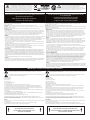 2
2
-
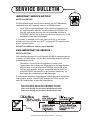 3
3
-
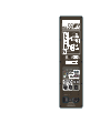 4
4
-
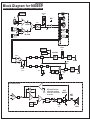 5
5
-
 6
6
-
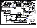 7
7
-
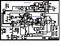 8
8
-
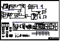 9
9
-
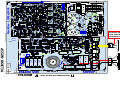 10
10
-
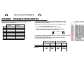 11
11
-
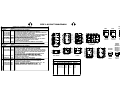 12
12
-
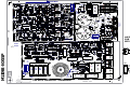 13
13
-
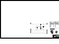 14
14
-
 15
15
-
 16
16
-
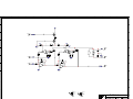 17
17
-
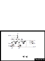 18
18
-
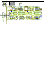 19
19
-
 20
20
-
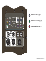 21
21
-
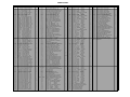 22
22


YORKVILLE NX55P Manuel utilisateur
- Catégorie
- Équipement musical supplémentaire
- Taper
- Manuel utilisateur
Documents connexes
-
YORKVILLE NX750P-2 Manuel utilisateur
-
YORKVILLE PSA2S Manuel utilisateur
-
 YORKVILLE V42 Manuel utilisateur
-
 YORKVILLE ELITE LS720P Manuel utilisateur
-
 YORKVILLE V44 Manuel utilisateur
-
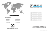 YORKVILLE AP2020 Manuel utilisateur
-
 YORKVILLE UCS1P Manuel utilisateur
-
 YORKVILLE NX750P Manuel utilisateur
-
-
 YORKVILLE NX55P-2 Manuel utilisateur


Autres documents
-
Yorkville Sound NX55P Manuel utilisateur
-
Crest Audio LQ10P LOUDSPEAKER - S Manuel utilisateur
-
Velleman WSSA122 Manuel utilisateur
-
Adidas AVUS-10421 Manuel utilisateur
-
Pyronix XDL15TT-AM Guide d'installation
-
JBSYSTEMS DIGIT 2K2 Le manuel du propriétaire
-
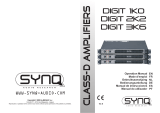 JBSYSTEMS DIGIT 2K2 Le manuel du propriétaire
-
-
Hitachi TAW-270NH2A Mode d'emploi
-
Renishaw Primo LTS software Siemens Mode d'emploi
