Indesit HI 50.A (WH)/1 Mode d'emploi
- Catégorie
- Fours
- Taper
- Mode d'emploi
Ce manuel convient également à

1
GB
OVEN
HI 50.B
HI 50.B IX
HI 500.B
HI 500.B IX
HIN 550
HIN 550 IX
HIN 5S
HIN 5S IX
HI 50.A
HI 50.A IX
HI 50.A/1
HI 50.A IX/1
Contents
Installation, 2-4
Positioning
Electrical connections
Data plate
Description of the appliance, 5
Overall view
Control panel
Start-up and use, 6
Starting the oven
Using the cooking timer
Cooking modes, 7-8
Cooking modes
Practical cooking advice
Cooking advice table
Hob, 9
Type of hob
Switching on the glass ceramic hob
Practical advice on using the glass ceramic hob
Precautions and tips, 10
General safety
Disposal
Respecting and conserving the environment
Maintenance and care, 11
Switching the appliance off
Cleaning the appliance
Cleaning the oven door
Replacing the light bulb
Assistance
Operating Instructions
Nederlands, 23English,1
Deutsch, 34 ÅëëçíéêÜ, 45
Français, 12
FRGB NL
DE GR
Espanol, 56
ES

2
GB
! Before placing your new appliance into operation
please read these operating instructions carefully.
They contain important information for safe use, for
installation and for care of the appliance.
! Please keep these operating instructions for future
reference. Pass them on to possible new owners of
the appliance.
Positioning
! Keep packaging material out of the reach of
children. It can become a choking or suffocation
hazard (
see Precautions and tips
).
! The appliance must be installed by a qualified
person in compliance with the instructions provided.
Incorrect installation may cause harm to persons,
animals or may damage property.
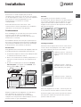
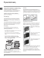
Fitting the appliance
Use the appropriate cabinet to ensure that the
appliance functions properly.
• The panels adjacent to the oven must be made of
heat-resistant material.
• Cabinets with a veneer exterior must be assembled
with glues which can withstand temperatures of up
to 100°C.
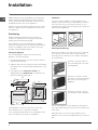
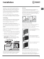
• To install the oven under the counter (
see
diagram
) and in a kitchen unit, the cabinet must
have the following dimensions:
! The appliance must not come into contact with
electrical parts once it has been installed.
The consumption indications on the data plate have
been calculated for this type of installation.
Ventilation
To ensure good ventilation, the back panel of the
cabinet must be removed. It is advisable to install the
oven so that it rests on two strips of wood, or on a
completely flat surface with an opening of at least 45 x
560 mm (
see diagrams
).
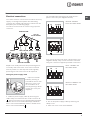
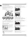
Centring and fastening
Position the 4 tabs on the side of the oven according
to the 4 holes of the outer frame. Adjust the tabs
according to the thickness of the cabinet side panel,
as shown below:
thickness of 20 mm: take off
the removable part of the tab
(
see diagram
)
thickness of 18 mm: use the
first groove, which has already
been set in the factory (
see
diagram
)
thickness of 16 mm: use the
second groove (
see diagram
)
Secure the appliance to the cabinet by opening the
oven door and putting 4 screws into the 4 holes of the
outer frame.
! All parts which ensure the safe operation of the
appliance must not be removable without the aid of a
tool.
595
558
min
45
min
575-585
min
560
+4 -0
480
+4 -0
547 min
555
580
500
39
15
595
23
572
543
543
545
560 mm.
45 mm.
Installation

3
GB
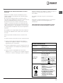
Electrical connections
The cooker must be connected to the mains electricity
supply. It is designed to operate with alternating
current at the voltage and frequency indicated on the
data plate (
see the following page
).
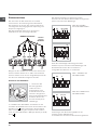
The hob is connected to the cooker using a special
connector.
BUILT-IN HOB
BUILT-IN COOKER
WHITE RED
YELLOW
BLUE GREEN
Only on
certain models
Replace the metal protection after performing all the
necessary hob connections. If the hob is removed
from its position, the red cap which was originally
protecting the red connector must be replaced.
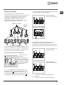
Fitting the power supply cable
1. Open the terminal
board by inserting a
screwdriver into the side
tabs of the cover. Use
the screwdriver as a
lever by pushing it down
to open the cover (
see
diagram
).
2. Install the power supply cable by loosening the
cable clamp screw and the wire contact screws L-N-
. Connect the wires to the corresponding terminals:
the Blue wire to the terminal marked (N), the Brown
wire to the terminal marked (L) and the Yellow Green
wire to the terminal marked
.
The terminal board is designed for a 400 V three-
phase connection (
see diagrams below
).
400V 3N~H05RR-F
5x2.5 CEI-UNEL 35363
If the electrical system has other characteristics (
see
diagrams below
), carry out the electrical connection
using the connection supports provided in the box P.
230V ~H05RR-F 3x4
CEI-UNEL 35363
400V 2N~H05RR-F 4x4
CEI-UNEL 35363
3. Secure the power supply cable by fastening the
clamp screw.
4. Close the cover of the terminal board.
NL1L3L2
1
3
2
4
5
N
L2
L1
L3
P
NL
1
3
2
4
5
NL1L2
1
3
2
4
5

4
GB
Connecting the supply cable to the mains
Install a standardised plug corresponding to the load
indicated on the data plate (
see side
).
The appliance must be directly connected to the
mains using an omnipolar circuit-breaker with a
minimum contact opening of 3 mm installed between
the appliance and the mains, suitable for the load
indicated and complying with current electrical
regulations (the earthing wire must not be interrupted
by the circuit-breaker). The supply cable must not
come into contact with surfaces with temperatures
higher than 50°C.
! The installer must ensure that the correct electrical
connection has been made and that it is compliant
with safety regulations.
Before connecting to the power supply, make sure that:
• The appliance is earthed and the plug is compliant
with the law.
• The socket can withstand the maximum power of
the appliance, which is indicated on the data plate
(
see below
).
• The voltage must be in the range between the
values indicated on the data plate (
see below
).
• The socket is compatible with the plug of the
appliance. If the socket is incompatible with the
plug, ask an authorised technician to replace it. Do
not use extension cords or multiple sockets.
! Once the appliance has been installed, the power
supply cable and the electrical socket must be easily
accessible.
! The cable must not be bent or compressed.
! The cable must be checked regularly and replaced
by authorised technicians only (
see Assistance
).
! The manufacturer declines any liability should
these safety measures not be observed.
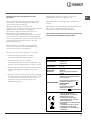
DATA PLATE
Dimensions
width 43.5 cm
height 32 cm
depth 40 cm
Volume lt. 56
Electrical
connections
voltage: 230V/400V~ 3N 50/60Hz
maximum power absorbed 8450W
ENERGY LABEL
Directive 2002/40/EC on the label
of electric ovens.
Standard EN 50304
Energy consumption for Forced
convection heating mode:
Multi-cooking
Declared energy consumption for
Natural convection Class heating
mode: Convection
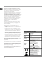
This appliance conforms to the
following European Economic
Community directives:
- 2006/ 95/EEC of 12/12/06 (Low
Volt age) and subsequent
amendments;
- 2004/ 108/ EEC of 15/12/04
(Electromagnetic Compatibility) and
subsequent amendments;
- 93/68/EEC of 22/07/93 and
subsequent amendments.
- 2002/96/EC and subsequent
amendments.

5
GB
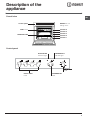
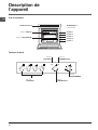
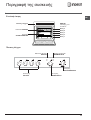
Control panel
GRILL rack
DRIPPING PAN
GUIDES for the
sliding racks
position 5
position 4
position 3
position 2
position 1
Description of the
appliance
Overall view
Control panel
SELECTORSELECTOR
SELECTORSELECTOR
SELECTOR
knob
HOTPLATES
indicator light
THERMOSTAT
knob
THERMOSTAT
indicator light
HOTPLATES
knob

6
GB
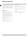
! The first time you use your appliance, heat the empty
oven with its door closed at its maximum temperature
for at least half an hour. Ensure that the room is well
ventilated before switching the oven off and opening
the oven door. The appliance may produce a slightly
unpleasant odour caused by the burning away of
protective substances used during the manufacturing
process.
Starting the oven
1. Select the desired cooking mode by turning the
SELECTOR knob.
2. Select the desired temperature with the
THERMOSTAT knob. See the Cooking advice table for
cooking modes and the suggested cooking
temperatures (
see Cooking Modes
).
3. When preheating is finished, the THERMOSTAT
indicator light will stay on: place the food in the oven.
4. You may do the following during cooking:
- change the cooking mode by turning the SELECTOR
knob.
- change the temperature by turning the
THERMOSTAT knob.
- stop cooking by turning the SELECTOR knob to the
“0” position.
! Never put objects directly on the oven bottom to
avoid damaging the enamel coating.
! Always place cookware on the rack(s) provided.
Cooling ventilation
In order to cool down the external temperature of the
oven, some models are fitted with a cooling fan that
blows out air between the control panel and the oven
door.
! Once the cooking has been completed, the cooling
fan remains on until the oven has cooled down
sufficiently.
Oven light
It goes on when selecting
with the SELECTOR
knob. It stays on when a cooking mode is selected.
Start-up and use

7
GB
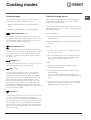
Cooking modes
! A temperature value can be set for all cooking
modes between 60°C and Max, except for
• GRILL (recommended: set only to MAX power
level);
• GRATIN (recommended: do not exceed 200°C).
TRADITIONAL OVEN mode
Both the top and bottom heating elements will come
on. With this traditional cooking mode, it is best to use
one cooking rack only; if more than one rack is used,
the heat will be distributed unevenly.
MULTI-COOKING mode
All the heating elements (top and bottom), as well as
the fan, will come on. Since the heat remains constant
throughout the oven, the air cooks and browns food
uniformly. A maximum of two racks may be used at
the same time.
TOP OVEN mode
The top heating element comes on. This mode can be
used to brown food at the end of cooking.
GRILL mode
The top heating element comes on. The extremely
high and direct temperature of the grill makes it
possible to brown the surface of meats and roasts
while locking in the juices to keep them tender. The
grill is also highly recommended for dishes that
require a high temperature on the surface: such as
beef steaks, veal, rib steak, filets, hamburgers etc...
Some grilling examples are included in the “Practical
Cooking Advice” paragraph. Always cook in this mode
with the oven door closed.
GRATIN mode
The top heating element, as well as the fan, will come
on. This combination of features increases the
effectiveness of the unidirectional thermal radiation of
the heating elements through forced circulation of the
air throughout the oven. This helps prevent food from
burning on the surface, allowing the heat to penetrate
right into the food. Always cook in this mode with the
oven door closed.
Cooking modes
Practical cooking advice
! Do not place racks in position 1 and 5 during fan-
assisted cooking. Excessive direct heat can burn
temperature sensitive foods.
! In the GRILL and GRATIN cooking modes, place the
dripping pan in position 1 to collect cooking residues
(fat and/or grease).
MULTI-COOKING
• Use position 2 and 4, placing the food that requires
more heat on 2.
• Place the dripping pan on the bottom and the rack
on top.
GRILL
• Insert the rack in position 3 or 4. Place the food in
the centre of the rack.
• We recommend that you set the maximum power
level. The top heating element is regulated by a
thermostat and may not always be on.
PIZZA
• For best results when cooking pizza, use the
MULTI-COOKING mode.
• Use a light aluminium pizza pan. Place it on the
rack provided.
For a crispy crust, do not use the dripping pan
(prevents crust from forming by extending cooking
time).
• If the pizza has a lot of toppings, we recommend
adding the mozzarella cheese on top of the pizza
halfway through the cooking process.

8
GB
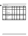
Cooking advice table
Cooking
modes
Foods
Weight
(in kg)
Rack
position
Pre-heating
time (m in)
Recommended
temperature
Cooking
time
(minutes)
Convection
Oven
Duck
Roast veal or beef
Pork roast
Biscuits (short pastry)
Tarts
1
1
1
-
1
3
3
3
3
3
1
5
15
15
15
15
200
200
200
180
180
65-7
5
70-75
70-80
15-20
30-35
Multi-cooking
Pizza (on 2 racks)
Lasagne
Lamb
Roast chicken + potatoes
Mackerel
Plum cake
Cream puffs (on 2 racks)
Biscuits (on 2 racks)
Sponge cake (on 1 rack)
Sponge cake (on 2 racks)
Savoury pies
1
1
1
1+1
1
1
0.5
0.5
0.5
1
1.5
2 and 4
3
2
2 and 4
2
2
2 and 4
2 and 4
2
2 and 4
3
1
5
10
10
15
10
10
10
10
10
10
15
230
180
180
200
180
170
190
180
170
170
200
15-2
0
30-35
40-45
60-70
30-35
40-50
20-25
10-15
15-20
20-25
25-30
Top oven Browning food to perfect cooking - 3/4 15 220 -
Grill
Soles and cuttlefish
Squid and prawn kebabs
Cod filet
Grilled vegetables
Veal steak
Cutlets
Hamburgers
Mackerels
Toasts
1
1
1
1
1
1
1
1
4
4
4
4
3 or 4
4
4
4
4
4
5
5
5
5
5
5
5
5
5
Max
Max
Max
Max
Max
Max
Max
Max
Max
8-10
6-8
10
10-15
15-20
15-20
7-10
15-20
2-3
Gratin
Grilled chicken
Cuttlefish
1.5
1.5
2
2
5
5
200
200
55-60
30-35

9
GB
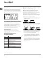
Hob
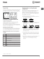
Type of hob
The oven is combined with a hob that can be made up of
two types of heating elements: cast-iron electric plates
(
see diagram 1
) or glass ceramic hobs (
see diagram 2
).
Switching on the glass ceramic hob
Traditional cooking zones
Traditional cooking zones are made up of circular
heating elements. They turn red approximately ten
seconds after they have been turned on.
Each cooking zone is fitted with a control knob allowing
you to select from 6 different temperature settings from a
minimum of 1 to a maximum of 6.
Residual heat indicator lights*
The indicator lights (C) indicate that the temperature of
the corresponding cooking zones have exceeded 60°C,
even after the heating element has been switched off.
Recommended power levels for various types of
cooking:
Setting
0
1
2
3
4
5
6
Setting
Off
Cooking vegetables, fish
Cooking patatoes (using steam) soups,
chickpeas, beans.
Continuing the cooking of large quantities of
food, minestrone.
For roasting (average)
For roasting (above average)
---------
For browning and reaching a boil in a short
time
Practical advice on using the glass
ceramic hob
! The glue that is applied on the gaskets leaves some
traces of grease on the glass. Before using the
appliance, we recommend you eliminate these with a
special non-abrasive cleaning product. During the first
few hours of use there may be a smell of rubber which
will disappear very quickly.
To obtain the best results with your hob:
• Use flat-bottomed pans to ensure that they adhere to
the cooking zone perfectly.
• Always use pans with a diameter that is large enough
to cover the hotplate fully, in order to use all the
available heat.
• Make sure that the bottom of the cookware is always
dry and clean to guarantee correct adherence and
long life, not only for the cooking zones but also for
the cookware itself.
• Avoid using the same cookware that is used on gas
burners: the heat concentration on gas burners may
deform the base of the pan, causing it not to adhere
correctly.
• Never leave a cooking zone on without cookware on it
because as it heats up and rapidly reaches the
maximum level, it could damage the heating
elements.
diagram 2
diagram 1
C
A
A
A
A
* Only on certain models

10
GB
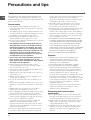
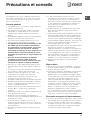
Precautions and tips
! The appliance was designed and manufactured in
compliance with international safety standards. The
following warnings are provided for safety reasons and
must be read carefully.
General safety
• The appliance was designed for domestic use
inside the home and is not intended for commercial
or industrial use.
• The appliance must not be installed outdoors, even
in covered areas. It is extremely dangerous to leave
the appliance exposed to rain and storms.
• When handling the appliance, always use the
handles provided on the sides of the oven.
• Do not touch the appliance with bare feet or with wet
or moist hands and feet.
• The appliance must be used by adults only for
the preparation of food, in accordance with the
instructions outlined in this booklet. Any other
use of the appliance (e.g. for heating the room)
constitutes improper use and is dangerous. The
manufacturer may not be held liable for any
damage resulting from improper, incorrect and
unreasonable use of the appliance.
• Do not touch the heating elements and parts of
the oven door when the appliance is in use;
these parts become extremely hot. Keep children
well away from the appliance.
• Ensure that the power supply cable of other
electrical appliances does not come into contact
with the hot parts of the oven.
• The openings used for ventilation and dispersion of
heat must never be covered.
• Always grip the oven door handle in the centre: the
ends may be hot.
• Always use oven gloves to place cookware in the
oven or when removing it.
• Do not use aluminium foil to line the bottom of the
oven.
• Do not place flammable materials in the oven: if the
appliance is switched on by mistake, it could catch
fire.
• Always make sure the knobs are in the “”/“
”
position when the appliance is not in use.
• When unplugging the appliance always pull the plug
from the mains socket, do not pull on the cable.
• Never carry out any cleaning or maintenance work
without having unplugged the plug from the mains.
• In the case of a malfunction, under no
circumstances should you attempt to repair the
appliance yourself. Repairs carried out by
inexperienced persons may cause injury or further
malfunctioning of the appliance. Contact a Service
Centre (
see Assistance
).
• Do not rest heavy objects on the open oven door.
• The glass ceramic hob is resistant to mechanical
shocks, but it may crack (or even break) if hit with a
sharp object such as a tool. If this happens,
disconnect the appliance from the electricity mains
immediately and contact a Service Centre.
• Remember that the temperature of the cooking
zones remains relatively high for at least thirty
minutes after they have been switched off.
• Keep any object that could melt away from the hob,
for example plastic and aluminium objects, or
products with a high sugar content. Keep plastic or
aluminium objects away from the hob: if you forget
them on surfaces that are still hot, they may cause
serious damage to the hob.
• The appliance should not be operated by people
(including children) with reduced physical, sensory
or mental capacities, by inexperienced individuals
or by anyone who is not familiar with the product.
These individuals should, at the very least, be
supervised by someone who assumes responsibility
for their safety or receive preliminary instructions
relating to the operation of the appliance.
• Do not let children play with the appliance.
Disposal
• Observe local environmental standards when
disposing packaging material for recycling
purposes. Observe existing legislation when
disposing of the old appliance.
• The European Directive 2002/96/EC on Waste
Electrical and Electronic Equipment (WEEE),
requires that old household electrical appliances
must not be disposed of in the normal unsorted
municipal waste stream. Old appliances must be
collected separately in order to optimise the
recovery and recycling of the materials they contain
and reduce the impact on human health and the
environment. The crossed out “wheeled bin” symbol
on the product reminds you of your obligation, that
when you dispose of the appliance it must be
separately collected.
Consumers should contact their local authority or
retailer for information concerning the correct
disposal of their old appliance.
Respecting and conserving the
environment
• By using the appliance in the hours between late
afternoon and early morning, you can help reduce
the work load placed on electrical companies.
• Always keep the oven door closed when using the
GRILL mode to attain best results and to save
energy (approximately 10%).
• Regularly check the door seals and wipe clean to
ensure they are free of debris so that they stick
properly to the door and do not allow heat to
disperse.

11
GB
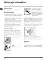
Switching the appliance off
Disconnect your appliance from the electricity supply
before carrying out any work on it.
Cleaning the appliance
• The stainless-steel or enamel-coated external parts
as well as the rubber seals may be cleaned using a
sponge that has been soaked in lukewarm water
and neutral soap. If these stains are difficult to
remove, use only specialised products. After
cleaning, rinse and dry thoroughly. Do not use
abrasive powders or corrosive substances.
• Ideally, the inside of the oven should be cleaned
after each use, when it is still lukewarm. Use hot
water and detergent, rinse and dry with a soft cloth.
Do not use abrasive products.
• The accessories can be washed like everyday
crockery (even in your dishwasher).
! Never use steam cleaners or pressure cleaners on
the appliance.
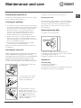
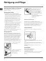
Cleaning the oven door
Clean the glass part of the oven door using a sponge
and a non-abrasive cleaning product, then dry
thoroughly with a soft cloth. Do not use rough abrasive
material or sharp metal scrapers as these could
scratch the surface and cause the glass to crack.
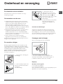
To clean more thoroughly, you can remove the oven door.
1. Open the oven door fully
(
see diagram
).
2. lift up and turn the small
levers situated on the two
hinges; (
see diagram
).
3. Grip the door on the two
external sides and close it
approximately half way. Unlock
the door by pressing on the
clamps
FF
FF
F, then pull the door
towards you lifting it out of its
seat (
see diagram
).
To replace the door, reverse this sequence.
Inspecting the seals
Check the door seals around the oven periodically. If
the seals are damaged, please contact your nearest
After-sales Service Centre (
see Assistance
). We
recommend not using the oven until the seals have
been replaced.
Replacing the light bulb
To replace the oven light bulb:
1. Remove the glass cover of the lamp-holder.
2. Remove the light bulb and replace it with a similar
one: Wattage 25 W, cap E 14.
3. Replace the glass cover (
see diagram
).
Assistance
Communicating:
• appliance model (Mod.)
• serial number (S/N)
This information is found on the data plate located on
the appliance and/or on the packaging.
F
F
Maintenance and care

12
FR
FOUR
Sommaire
Installation, 13-15
Positionnement
Raccordement électrique
Plaquette signalétique
Description de l’appareil, 16
Vue d’ensemble
Tableau de bord
Mise en marche et utilisation, 17
Mise en marche du four
Programmes, 18-19
Programmes de cuisson
Conseils de cuisson
Tableau de cuisson
Table de cuisson, 20
Type de table
Mise sous tension de la table vitrocéramique
Conseils d’utilisation de la table vitrocéramique
Précautions et conseils, 21
Sécurité générale
Mise au rebut
Economies et respect de l’environnement
Nettoyage et entretien, 22
Mise hors tension
Nettoyage de l’appareil
Nettoyage de la porte
Remplacement de l’ampoule d’éclairage
Assistance
Mode d’emploi
GB FR
HI 50.B
HI 50.B IX
HI 500.B
HI 500.B IX
HIN 550
HIN 550 IX
HIN 5S
HIN 5S IX
HI 50.A
HI 50.A IX
HI 50.A/1
HI 50.A IX/1
Nederlands, 23English,1
Deutsch, 34 ÅëëçíéêÜ, 45
Français, 12
NL
DE GR
Espanol, 56
ES

13
FR
! Conservez ce mode d’emploi pour pouvoir le
consulter à tout moment. En cas de vente, de cession
ou de déménagement, veillez à ce qu’il suive l’appareil
pour informer le nouveau propriétaire sur son
fonctionnement et lui fournir les conseils
correspondants.
! Lisez attentivement les instructions : elles
contiennent des conseils importants sur l’installation,
l’utilisation et la sécurité de votre appareil
Positionnement
! Les emballages ne sont pas des jouets pour enfants,
il faut les mettre au rebut en respectant la
réglementation sur le tri sélectif des déchets (
voir
Précautions et conseils
).
! L’installation doit être effectuée par un professionnel
du secteur conformément aux instructions du fabricant.
Une mauvaise installation peut causer des dommages
à des personnes, des animaux ou des biens.
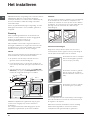
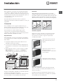
Encastrement
Pour garantir le bon fonctionnement de l’appareil, il faut que
le meuble possède des caractéristiques bien précises :
• les panneaux adjacents doivent être fabriqués dans
un matériau résistant à la chaleur ;
• dans le cas notamment de meubles plaqués bois, il
faut que les colles résistent à une température de
100°C ;
• la cavité du meuble pour encastrement du four,
tant sous plan (
voir figure
) qu’en colonne , doit
avoir les dimensions suivantes :
! Après encastrement de l’appareil, il ne doit plus y
avoir possibilité de contact avec les parties
électrifiées. Les déclarations de consommation
indiquées sur l’étiquette des caractéristiques ont été
mesurées pour ce type d’installation.
Aération
Pour garantir une bonne aération, la cavité
d’encastrement doit être dépourvue de paroi arrière. Il
est conseillé d’installer le four de manière à ce qu’il
repose sur deux cales en bois ou bien sur un plan
d’appui continu qui ait une découpe d’au moins 45 x
560 mm (
voir figures
).
Centrage et fixation
Positionnez les 4 taquets situés sur les côtés du four
en face des 4 trous pratiqués sur le cadre et réglez-
les selon l’épaisseur de la joue du meuble :
épaisseur 20 mm : enlevez la
partie amovible du taquet (
voir
figure
) ;
épaisseur 18 mm : utilisez la
première rainure, comme prévu
par le fabricant (
voir figure
);
épaisseur 16 mm : utilisez la
deuxième rainure (
voir figure
).
Pour fixer l’appareil au meuble : ouvrez la porte du
four et vissez 4 vis à bois dans les 4 trous du cadre.
! Toutes les parties qui servent de protection doivent
être fixées de manière à ne pouvoir être enlevées
qu’avec l’aide d’un outil.
595
558
min
45
min
575-585
min
560
+4 -0
480
+4 -0
547 min
555
580
500
39
15
595
23
572
543
543
545
560 mm.
45 mm.
Installation

14
FR
Raccordement électrique
Le raccordement électrique au réseau doit être
effectué sur le four qui est prévu pour fonctionner en
courant alternatif à la tension et fréquence
d’alimentation indiquées sur la plaquette signalétique
(
voir page suivante
).
La table de cuisson est raccordée au four à l’aide
d’un connecteur spécial.
Table à encastrer
CUISINIERE A ENCASTRER
BLANC ROUGE JAUNE BLEU VERT
N'existe que
sur certains
modèles
Remettre la protection métallique en place après avoir
connecté la table. En cas de démontage de la table,
remettre le bouchon rouge d'origine sur le connecteur
rouge.
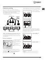
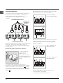
Montage du câble d’alimentation
1. Pour ouvrir le bornier,
faites pression à l’aide
d’un tournevis sur les
languettes latérales du
couvercle : tirez et
ouvrez le couvercle (
voir
figure
).
2. Montage du câble d’alimentation : dévissez la vis
du serre-câble ainsi que les trois vis des contacts L-
N-
puis fixez les fils sous les têtes de vis en
respectant les couleurs Bleu (N) Marron (L) Jaune-
Vert (
).
Le bornier est prévu pour raccordement à 400 V
triphasé (
voir figures ci-dessous
).
400V 3N~H05RR-F
5x2.5 CEI-UNEL 35363
Si l’installation électrique présente d’autres
caractéristiques (
voir figures ci-dessous
), procédez
au raccordement électrique au moyen des cavaliers
de raccordement logés dans le boîtier P.
230V ~H05RR-F 3x4
CEI-UNEL 35363
400V 2N~H05RR-F 4x4
CEI-UNEL 35363
3. Fixez le câble d’alimentation dans le serre-câble
prévu.
4. Fermez le couvercle du bornier.
NL1L3L2
1
3
2
4
5
N
L2
L1
L3
P
NL
1
3
2
4
5
NL1L2
1
3
2
4
5

15
FR
Branchement du câble d’alimentation au réseau
électrique
Montez sur le câble une prise normalisée pour la
charge indiquée sur l’étiquette des caractéristiques
(
voir ci-contre
).
En cas de raccordement direct au réseau, il faut
intercaler entre l’appareil et le réseau un interrupteur à
coupure omnipolaire ayant au moins 3 mm
d’écartement entre les contacts, dimensionné à la
charge et conforme aux normes en vigueur (le fil de
terre ne doit pas être interrompu par l’interrupteur). Le
câble d’alimentation ne doit atteindre, en aucun point,
des températures dépassant de 50°C la température
ambiante.
! L’installateur est responsable du bon raccordement
électrique de l’appareil et du respect des normes de
sécurité.
Avant de procéder au branchement, assurez-vous
que :
• la prise est bien munie d’une terre conforme à la loi;
• la prise est bien apte à supporter la puissance
maximale de l’appareil, indiquée sur la plaquette
signalétique (
voir ci-dessous
);
• la tension d’alimentation est bien comprise entre les
valeurs indiquées sur la plaquette signalétique (
voir
ci-dessous
);
• la prise est bien compatible avec la fiche de
l’appareil. Si ce n’est pas le cas, remplacez la prise
ou la fiche, n’utilisez ni rallonges ni prises multiples.
PLAQUETTE SIGNALETIQUE
Dimensions
largeur cm 43,5
hauteur cm 32
profondeur cm 40
Volume l 56
Raccordement s
électriques
tension 230V/400V~ 3N 50/60Hz
puissance maxi. absorbée 8450W
ETIQUETTE
ENERGIE
Directive 2002/40/CE sur l'étiquet te
des fours électriques
Norme EN 50304
Consommation énergie convection
forcée
fonction four : Multicuisson
Consommation énergie déclarée
pour Classe convection nat urelle
fonction four : Traditionnel
Cet appareil est conforme aux
Directives Communaut aires
suivantes :
- 2006/ 95/CEE du 12/12/06 (Basse
Tension) et modifications
successives
- 2004/ 108/CEE du 15/12/04
(Compatibilité électromagnétique)
et modifications successives
- 93/68/CEE du 22/07/93 et
modifications successives
- 2002/ 96/EC et modifications
successives
! Après installation de l’appareil, le câble électrique et
la prise de courant doivent être facilement
accessibles
! Le câble ne doit être ni plié ni excessivement
écrasé.
! Il doit être contrôlé périodiquement et ne peut être
remplacé que par un technicien agréé (
voir
Assistance
).
! Nous déclinons toute responsabilité en cas de
non respect des normes énumérées ci-dessus.

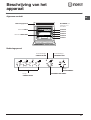
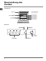
16
FR
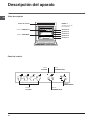
Tableau de bord
Support GRILLE
Support LECHEFRITE
GLISSIERES de
coulissement
niveau 5
niveau 4
niveau 3
niveau 2
niveau 1
Description de
l’appareil
Vue d’ensemble
Tableau de bord
Bouton
PROGRAMMES
Voyant
PLAQUES
Bouton
THERMOSTAT
Voyant
THERMOSTAT
Bouton
PLAQUES

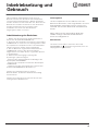
17
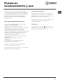
FR
! Lors de son premier allumage, faites fonctionner le
four à vide, porte fermée, pendant au moins une heure
en réglant la température à son maximum. Puis
éteignez-le, ouvrez la porte et aérez la pièce. L’odeur
qui se dégage est due à l’évaporation des produits
utilisés pour protéger le four.
Mise en marche du four
1. Pour sélectionner le programme de cuisson
souhaité, tournez le bouton PROGRAMMES.
2. Pour choisir la température, tournez le bouton
THERMOSTAT. Un tableau de cuisson vous guidera
dans vos cuissons en vous indiquant notamment les
températures conseillées pour chacune d’elles (
voir
Programmes
).
3. Le voyant THERMOSTAT reste allumé pendant la
durée de montée en température.
4. En cours de cuisson, vous pouvez à tout moment :
- modifier le programme de cuisson à l’aide du bouton
PROGRAMMES;
- modifier la température à l’aide du bouton
THERMOSTAT ;
- interrompre la cuisson en ramenant le bouton
PROGRAMMES sur “0”.
! Ne posez jamais d’objets à même la sole du four,
vous pourriez abîmer l’émail.
! Placez toujours vos plats sur la grille fournie avec
l’appareil.
Système de refroidissement
Pour obtenir un abaissement des températures
extérieures, certains modèles sont équipés d’un
système de refroidissement. Ce dernier souffle de l’air
à l’extérieur par une fente située entre le tableau de
bord et la porte du four.
! Le ventilateur continue à tourner après l’arrêt du four
jusqu’à ce que ce dernier se soit suffisamment
refroidi.
Eclairage du four
Pour l’allumer, sélectionnez
à l’aide du bouton
PROGRAMMES. La lampe reste allumée quand vous
sélectionnez un programme de cuisson.
Mise en marche et
utilisation

18
FR
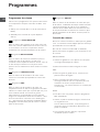
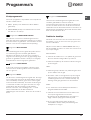
Programmes de cuisson
! Pour tous les programmes vous pouvez sélectionner
une température comprise entre 60°C et MAX., sauf
pour :
• GRIL (il est conseillé dans ce cas de sélectionner
MAX.);
• GRATIN (il est conseillé de ne pas dépasser
200°C).
Programme FOUR TRADITION
Mise en marche des résistances de voûte et de sole.
Pour cette cuisson traditionnelle mieux vaut cuire sur
un seul niveau : la cuisson sur plusieurs niveaux
entraînerait une mauvaise distribution de la chaleur.
Programme MULTICUISSON
Mise en marche de toutes les résistances (sole et
voûte) ainsi que de la turbine. La chaleur est
constante et bien répartie à l’intérieur du four, l’air cuit
et dore de façon uniforme en tous points. Vous
pouvez cuire au maximum sur deux niveaux en même
temps.
Programme CHALEUR VOUTE
Mise en marche de la résistance de voûte. Cette
fonction est conseillée pour parfaire la cuisson des
aliments.
Programme GRIL
Mise en marche de la résistance de voûte. La
température élevée et directe du gril permet de saisir
l’aliment en surface pour qu’il ne perde pas son jus et
reste tendre à souhait. La cuisson au gril est
particulièrement recommandée pour les plats qui
exigent une température élevée à leur surface : côtes
de veau et de bœuf, entrecôtes, filet, hamburgers,
etc... Vous trouverez des exemples d’utilisation dans le
paragraphe “Conseils utiles pour la cuisson”. Cuisson
porte du four fermée.
Programme GRATIN
Mise en marche de la résistance de voûte ainsi que
de la turbine. L’irradiation thermique unidirectionnelle
s’ajoute au brassage de l’air pour une répartition
uniforme de la chaleur dans l’enceinte du four. Plus
de risques de brûler vos aliments en surface et plus
grande pénétration de la chaleur. Cuisson porte du
four fermée.
Conseils de cuisson
! Pour vos cuissons ventilées n’utilisez pas les gradins
1et 5 : ils sont directement frappés par l’air chaud qui
pourrait brûler vos mets délicats.
! En cas de cuisson en mode GRIL ou GRATIN,
placez la lèchefrite au gradin 1 pour récupérer les jus
de cuisson.
MULTICUISSON
• Utilisez les gradins 2 et 4 et placez au 2 les plats
qui exigent davantage de chaleur.
• Placez la lèchefrite en bas et la grille en haut.
GRIL
• Placez la grille au gradin 3 ou 4, enfournez vos
plats au milieu de la grille.
• Nous conseillons de sélectionner le niveau
d’énergie maximum. Ne vous inquiétez pas si la
résistance de voûte n’est pas allumée en
permanence : son fonctionnement est contrôlé par
un thermostat.
PIZZA
• Pour bien cuire vos pizzas, utilisez le programme
MULTICUISSON.
• Utilisez un plat en aluminium léger et enfournez-le
sur la grille du four.
Si vous utilisez la lèchefrite, vous prolongerez le
temps de cuisson et obtiendrez difficilement une
pizza croustillante.
• Si vos pizzas sont bien garnies, n’ajoutez la
mozzarelle qu’à mi-cuisson.
Programmes

19
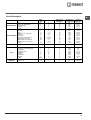
FR
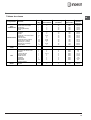
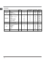
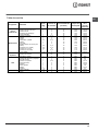
Tableau de cuisson
Programmes Aliments
Poids
(Kg)
Niveau
enfournement
Préchauffage
(minutes)
Température
préconisée
Durée
cuisson
(minutes)
Four
Traditionnel
Canard
Rôti de veau ou de bœuf
Rôti de porc
Biscuits (pâte brisée)
Tartes
1
1
1
-
1
3
3
3
3
3
15
15
15
15
15
200
200
200
180
180
65-75
70-75
70-80
15-20
30-35
Multicuisson
Pizza (sur 2 niveaux)
Lasagnes
Agneau
Poulet rôti + pommes de terre
Maquereau
Cake aux fruits
Profiteroles (sur 2 niveaux)
Biscuits (sur 2 niveaux)
Génoise (sur 1 niveau)
Génoise (sur 2 niveaux)
Tartes salées
1
1
1
1+1
1
1
0.5
0.5
0.5
1
1.5
2 et 4
3
2
2 et 4
2
2
2 et 4
2 et 4
2
2 et 4
3
15
10
10
15
10
10
10
10
10
10
15
230
180
180
200
180
170
190
180
170
170
200
15-20
30-35
40-45
60-70
30-35
40-50
20-25
10-15
15-20
20-25
25-30
Résistance de
voûte
Pour parfaire la cuisson - 3/4 15 220 -
Gril
Soles et seiches
Brochettes de calmars et de
crevettes
Tranches de colin
Légumes grillés
Steaks de veau
Côtelettes
Hamburgers
Maquereaux
Croque-monsieur
1
1
1
1
1
1
1
1
n. 4
4
4
4
3 ou 4
4
4
4
4
4
5
5
5
5
5
5
5
5
5
Max.
Max.
Max.
Max.
Max.
Max.
Max.
Max.
Max.
8-10
6-8
10
10-15
15-20
15-20
7-10
15-20
2-3
Gratin
Poulet grillé
Seiches
1.5
1.5
2
2
5
5
200
200
55-60
30-35

20
FR
Table de cuisson
Conseils d’utilisation de la table
vitrocéramique
! La colle utilisée pour les joints laisse des traces de
graisse sur le verre. Nous vous conseillons de les
éliminer avant d’utiliser l’appareil, à l’aide d’un produit
d’entretien non abrasif. Une odeur de caoutchouc peut
se dégager au cours des premières heures d’utilisation,
elle disparaîtra très vite.
Pour obtenir de meilleures performances de votre table
de cuisson :
• utilisez des casseroles à fond plat pour qu’elles
adhèrent parfaitement à la zone de chauffe
• utilisez toujours des casseroles dont le diamètre couvre
complètement la zone de chauffe de façon à ce que
toute la chaleur disponible puisse être utilisée ;
• veillez à ce que la base des casseroles soit toujours
bien sèche et propre, pour garantir un bon contact et
une longue durée de vie des foyers mais aussi des
casseroles ;
• évitez d’utiliser les casseroles que vous utilisez sur les
brûleurs à gaz. la concentration de chaleur sur les
brûleurs à gaz peut déformer le fond de la casserole
qui perd son adhérence ;
• ne laissez jamais un foyer allumé sans casserole car,
dans ce cas, le niveau maximum de chaleur est
atteint très rapidement et les éléments chauffants
risquent de s’endommager.
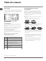
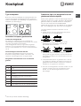
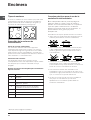
Type de table
Le four est associé à une table de cuisson équipée, au
choix, de deux types de foyers : des plaques électriques
en fonte (
voir figure 1
) ou des plans vitrocéramique (
voir
figure 2
) .
Mise sous tension de la table
vitrocéramique
Foyers traditionnels
Les foyers radiants traditionnels sont constitués de
spires qui deviennent rouges en quelques dizaines de
secondes.
Chaque foyer est équipé d’un bouton de commande
permettant de sélectionner 6 températures au choix
allant d’un minimum de 1 à un maximum de 6.
Voyants de chaleur résiduelle*
Les voyants (C) indiquent que la température du foyer
correspondant est supérieure à 60°C, même après
l’arrêt.
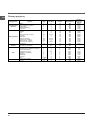
Niveaux de puissance conseillés pour les
différents types de cuisson :
Position
0
1
2
3
4
5
6
Plaque normale ou rapide
Eteint.
Cuisson de légumes verts, poissons.
Cuisson de pommes de terre (à la vapeur)
soupes, pois chiches, haricots.
Pour continuer la cuisson de grandes
quantités d'aliments, minestrone.
Rôtir (moyen).
Rôtir (fort).
Rissoler ou rejoindre l'ébullition en peu de
temps.
figure 2
figure 1
C
A
A
A
A
*
N’existe que sur certains modèles
La page est en cours de chargement...
La page est en cours de chargement...
La page est en cours de chargement...
La page est en cours de chargement...
La page est en cours de chargement...
La page est en cours de chargement...
La page est en cours de chargement...
La page est en cours de chargement...
La page est en cours de chargement...
La page est en cours de chargement...
La page est en cours de chargement...
La page est en cours de chargement...
La page est en cours de chargement...
La page est en cours de chargement...
La page est en cours de chargement...
La page est en cours de chargement...
La page est en cours de chargement...
La page est en cours de chargement...
La page est en cours de chargement...
La page est en cours de chargement...
La page est en cours de chargement...
La page est en cours de chargement...
La page est en cours de chargement...
La page est en cours de chargement...
La page est en cours de chargement...
La page est en cours de chargement...
La page est en cours de chargement...
La page est en cours de chargement...
La page est en cours de chargement...
La page est en cours de chargement...
La page est en cours de chargement...
La page est en cours de chargement...
La page est en cours de chargement...
La page est en cours de chargement...
La page est en cours de chargement...
La page est en cours de chargement...
La page est en cours de chargement...
La page est en cours de chargement...
La page est en cours de chargement...
La page est en cours de chargement...
La page est en cours de chargement...
La page est en cours de chargement...
La page est en cours de chargement...
La page est en cours de chargement...
La page est en cours de chargement...
La page est en cours de chargement...
La page est en cours de chargement...
La page est en cours de chargement...
-
 1
1
-
 2
2
-
 3
3
-
 4
4
-
 5
5
-
 6
6
-
 7
7
-
 8
8
-
 9
9
-
 10
10
-
 11
11
-
 12
12
-
 13
13
-
 14
14
-
 15
15
-
 16
16
-
 17
17
-
 18
18
-
 19
19
-
 20
20
-
 21
21
-
 22
22
-
 23
23
-
 24
24
-
 25
25
-
 26
26
-
 27
27
-
 28
28
-
 29
29
-
 30
30
-
 31
31
-
 32
32
-
 33
33
-
 34
34
-
 35
35
-
 36
36
-
 37
37
-
 38
38
-
 39
39
-
 40
40
-
 41
41
-
 42
42
-
 43
43
-
 44
44
-
 45
45
-
 46
46
-
 47
47
-
 48
48
-
 49
49
-
 50
50
-
 51
51
-
 52
52
-
 53
53
-
 54
54
-
 55
55
-
 56
56
-
 57
57
-
 58
58
-
 59
59
-
 60
60
-
 61
61
-
 62
62
-
 63
63
-
 64
64
-
 65
65
-
 66
66
-
 67
67
-
 68
68


Indesit HI 50.A (WH)/1 Mode d'emploi
- Catégorie
- Fours
- Taper
- Mode d'emploi
- Ce manuel convient également à
dans d''autres langues
- English: Indesit HI 50.A (WH)/1 User guide
- español: Indesit HI 50.A (WH)/1 Guía del usuario
- Deutsch: Indesit HI 50.A (WH)/1 Benutzerhandbuch
- Nederlands: Indesit HI 50.A (WH)/1 Gebruikershandleiding
- slovenčina: Indesit HI 50.A (WH)/1 Užívateľská príručka
Documents connexes
-
Indesit HIN 550 IX Manuel utilisateur
-
Indesit HI 500.B IX Mode d'emploi
-
-
-
Whirlpool KN3C55(W)/FR Le manuel du propriétaire
-
-
Whirlpool IW5VMC1A(X) FR Mode d'emploi
-