RotoZip DR1 Manuel utilisateur
- Catégorie
- Outils électroportatifs
- Taper
- Manuel utilisateur
Ce manuel convient également à

IMPORTANT: IMPORTANT : IMPORTANTE:
Read Before Using Lire avant usage Leer antes de usar
For English Version Version française Versión en español
See page 2 Voir page 13 Ver la página 24
Operating/Safety Instructions
Consignes de fonctionnement/sécurité
Instrucciones de funcionamiento y seguridad
1-877-ROTOZIP (1-877-768-6947) www.rotozip.com
Call Toll Free for
Consumer Information
& Service Locations
Pour obtenir des informations
et les adresses de nos centres
de service après-vente,
appelez ce numéro gratuit
Llame gratis para
obtener información
para el consumidor y
ubicaciones de servicio
DR1
RZ 2610955525 10-07 10/11/07 8:19 AM Page 1

-2-
Work area safety
Keep work area clean and well lit. Cluttered
or dark areas invite accidents.
Do not operate power tools in explosive
atmospheres, such as in the presence of
flammable liquids, gases or dust. Power
tools create sparks which may ignite the dust
or fumes.
Keep children and bystanders away while
operating a power tool. Distractions can
cause you to lose control.
Electrical safety
Power tool plugs must match the outlet.
Never modify the plug in any way. Do not
use any adapter plugs with earthed
(grounded) power tools. Unmodified plugs
and matching outlets will reduce risk of electric
shock.
Avoid body contact with earthed or
grounded surfaces such as pipes,
radiators, ranges and refrigerators. There is
an increased risk of electric shock if your body
is earthed or grounded.
Do not expose power tools to rain or wet
conditions. Water entering a power tool will
increase the risk of electric shock.
Do not abuse the cord. Never use the cord
for carrying, pulling or unplugging the
power tool. Keep cord away from heat, oil,
sharp edges or moving parts. Damaged or
entangled cords increase the risk of electric
shock.
When operating a power tool outdoors, use
an extension cord suitable for outdoor use.
Use of a cord suitable for outdoor use reduces
the risk of electric shock.
Do not use AC only rated tools with a DC
power supply. While the tool may appear to
work, the electrical components of the AC
rated tool are likely to fail and create a hazard
to the operator.
If operating the power tool in damp
locations is unavoidable a Ground Fault
Circuit Interrupter (GFCI) must be used to
supply the power to your tool. GFCI and
personal protection devices like electrician’s
rubber gloves and footwear will further
enhance your personal safety.
Personal safety
Stay alert, watch what you are doing and
use common sense when operating a
power tool. Do not use a power tool while
you are tired or under the influence of
drugs, alcohol or medication. A moment of
inattention while operating power tools may
result in serious personal injury.
Use safety equipment. Always wear eye
protection. Safety equipment such as dust
mask, non-skid safety shoes, hard hat, or
hearing protection used for appropriate
conditions will reduce personal injuries.
Avoid accidental starting. Ensure the
switch is in the off-position before
plugging in. Carrying power tools with your
finger on the switch or plugging in power tools
that have the switch on invites accidents.
Remove any adjusting key or wrench
before turning the power tool on. A wrench
or a key left attached to a rotating part of the
power tool may result in personal injury.
Do not overreach. Keep proper footing and
balance at all times. This enables better
control of the power tool in unexpected
situations.
Dress properly. Do not wear loose clothing
or jewelry. Keep your hair, clothing and
gloves away from moving parts. Loose
clothes, jewelry or long hair can be caught in
moving parts.
If devices are provided for the connection
of dust extraction and collection facilities,
ensure these are connected and properly
used. Use of these devices can reduce dust-
related hazards.
Keep handles dry, clean and free from oil
and grease. Slippery hands cannot safely
control the power tool.
Read all instructions. Failure to follow all instructions listed below may
result in electric shock, fire and/or serious injury. The term “power tool” in
all of the warnings listed below refers to your mains-operated (corded) power tool or battery-
operated (cordless) power tool.
SAVE THESE INSTRUCTIONS
!
WARNING
General Safety Rules
RZ 2610955525 10-07 10/11/07 8:19 AM Page 2

-3-
Drywall Router Safety Rules
Hold tool by insulated gripping surfaces
when performing an operation where the
cutting tool may contact hidden wiring or
its own cord. Contact with a "live" wire will
make exposed metal parts of the tool "live" and
shock the operator.
Use clamps or other practical way to
secure and support the workpiece to a
stable platform. Holding the work by hand or
against your body is unstable and may lead to
loss of control.
If cutting into existing walls or other blind areas
where electrical wiring may exist is
unavoidable, disconnect all fuses or circuit
breakers feeding this worksite.
Always make sure the work surface is free
from nails and other foreign objects.
Cutting into a nail can cause the bit and the
tool to jump and damage the bit.
Never hold the workpiece in one hand and
the tool in the other hand when in use.
Never place hands near or below cutting
surface. Clamping the material and guiding
the tool with both hands is safer.
Never lay workpiece on top of hard
surfaces, like concrete, stone, etc...
Protruding cutting bit may cause tool to jump.
Always wear safety goggles and dust
mask. Use only in well ventilated area.
Power tool use and care
Do not force the power tool. Use the correct
power tool for your application. The correct
power tool will do the job better and safer at
the rate for which it was designed.
Do not use the power tool if the switch
does not turn it on and off. Any power tool
that cannot be controlled with the switch is
dangerous and must be repaired.
Disconnect the plug from the power source
and/or the battery pack from the power tool
before making any adjustments, changing
accessories, or storing power tools. Such
preventive safety measures reduce the risk of
starting the power tool accidentally.
Store idle power tools out of the reach of
children and do not allow persons
unfamiliar with the power tool or these
instructions to operate the power tool.
Power tools are dangerous in the hands of
untrained users.
Maintain power tools. Check for
misalignment or binding of moving parts,
breakage of parts and any other condition
that may affect the power tools operation. If
damaged, have the power tool repaired
before use. Many accidents are caused by
poorly maintained power tools.
Keep cutting tools sharp and clean.
Properly maintained cutting tools with sharp
cutting edges are less likely to bind and are
easier to control.
Use the power tool, accessories and tool
bits etc., in accordance with these
instructions and in the manner intended for
the particular type of power tool, taking into
account the working conditions and the
work to be performed. Use of the power tool
for operations different from those intended
could result in a hazardous situation.
Use clamps or other practical way to
secure and support the workpiece to a
stable platform. Holding the work by hand or
against your body is unstable and may lead to
loss of control.
Service
Have your power tool serviced by a
qualified repair person using only identical
replacement parts. This will ensure that the
safety of the power tool is maintained.
Develop a periodic maintenance schedule
for your tool. When cleaning a tool be
careful not to disassemble any portion of
the tool since internal wires may be
misplaced or pinched or safety guard
return springs may be improperly mounted.
Certain cleaning agents such as gasoline,
carbon tetrachloride, ammonia, etc. may
damage plastic parts.
Risk of injury to user, power cord must only be
serviced by a Rotozip/Bosch Factory Service
Center or Authorized Rotozip/Bosch Service
Station.
SAVE THESE INSTRUCTIONS
RZ 2610955525 10-07 10/11/07 8:19 AM Page 3

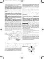
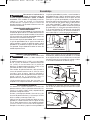
The Model DR01-1100TL is equipped with a
“Twist-To-Lock” male connector as shown. Use
only a 3-wire extension cord which has a mating
“Twist-To-Lock” female connector on one end
and a 3-prong grounding plug on the other end.
(See Electrical Safety section on page 2 for
grounding information.)
-4-
Using personal safety devices and working in
safe environment reduces risk of injury.
After changing the bits or making any
adjustments, make sure the collet nut and
any other adjustment devices are securely
tightened. Loose adjustment device can
unexpectedly shift, causing loss of control,
loose rotating components will be violently
thrown.
Never start the tool when the bit is engaged
in the material. The bit cutting edge may grab
the material causing loss of control of the
cutter.
Always hold the tool with two hands during
start-up. The reaction torque of the motor can
cause the tool to twist.
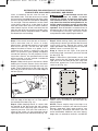
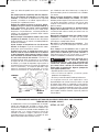
When routing or cutting, the direction of
feed with the bit’s cutting edge into the
material is very important. Always feed the
bit into the material in the same direction
as the cutting edge is exiting from the
material. When viewing the tool from the top,
the bit rotates clockwise. If the tool is between
the workpiece and your body, then feed the
tool to your right. If the workpiece is between
the tool and your body, then feed the tool to
your left. Feeding the tool in the wrong
direction causes the cutting edge of the bit to
climb out of the work and pull the tool in the
direction of this feed.
Never use dull or damaged bits. Sharp bits
must be handled with care. Damaged bits
can snap during use. Dull bits require more
force to push the tool, possibly causing the bit
to break.
Never touch the bit during or immediately
after the use. After use the bit is too hot to be
touched by bare hands.
Never lay the tool down until the motor has
come to a complete standstill. The spinning
bit can grab the surface and pull the tool out of
your control.
Do not use the tool for drilling purposes.
This tool is not intended to be used with drill
bits.
Always use the tool with the depth guide
securely attached and positioned flat
against material being cut. The guide
securely positioned on the material improves
the stability and control of your tool.
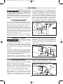
Some dust created by
power sanding, sawing,
grinding, drilling, and other construction
activities contains chemicals known to
cause cancer, birth defects or other
reproductive harm. Some examples of
these chemicals are:
• Lead from lead-based paints,
• Crystalline silica from bricks and cement and
other masonry products, and
• Arsenic and chromium from chemically-
treated lumber.
Your risk from these exposures varies,
depending on how often you do this type of
work. To reduce your exposure to these
chemicals: work in a well ventilated area, and
work with approved safety equipment, such as
those dust masks that are specially designed
to filter out microscopic particles.
!
WARNING
BIT
WORK
DIRECTION OF
FEED
START
HERE
TWIST-TO-LOCK CONNECTOR INSTRUCTIONS FOR MODEL DR01-1100TL ONLY
20 AMP, 125 VOLT “TWIST-TO-LOCK”
NEMA L5-20P
RZ 2610955525 10-07 10/11/07 8:19 AM Page 4

-5-
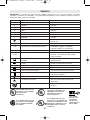
IMPORTANT: Some of the following symbols may be used on your tool. Please study them
and learn their meaning. Proper interpretation of these symbols will allow you to operate the
tool better and safer.
Symbol Name Designation/Explanation
V Volts Voltage (potential)
A Amperes Current
Hz Hertz Frequency (cycles per second)
W Watt Power
kg Kilograms Weight
min Minutes Time
s Seconds Time
Diameter Size of drill bits, grinding wheels, etc.
n
0
No load speed Rotational speed, at no load
.../min Revolutions or reciprocation per minute Revolutions, strokes, surface speed,
orbits etc. per minute
0 Off position Zero speed, zero torque...
1, 2, 3, ... Selector settings Speed, torque or position settings.
I, II, III, Higher number means greater speed
Infinitely variable selector with off Speed is increasing from 0 setting
Arrow Action in the direction of arrow
Alternating current Type or a characteristic of current
Direct current Type or a characteristic of current
Alternating or direct current Type or a characteristic of current
Class II construction Designates Double Insulated
Construction tools.
Earthing terminal Grounding terminal
Warning symbol Alerts user to warning messages
Ni-Cad RBRC seal Designates Ni-Cad battery recycling
program
Symbols
0
This symbol designates
that this tool is listed by
Underwriters Laboratories.
This symbol designates
that this tool is listed by
the Canadian Standards
Association.
This symbol designates
that this tool is listed to
Canadian Standards by
Underwriters Laboratories.
This symbol
designates
that
this tool
complies
to NOM
Mexican
Standards.
This symbol designates that
this tool is listed by
Underwriters Laboratories,
and listed to Canadian
Standards by Underwriters
Laboratories.
RZ 2610955525 10-07 10/11/07 8:19 AM Page 5

-6-
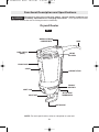
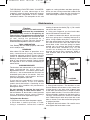
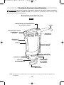
Functional Description and Specifications
Disconnect the plug from the power source before making any
assembly, adjustments or changing accessories. Such preventive safety
measures reduce the risk of starting the tool accidentally.
!
WARNING
NOTE: For tool specifications refer to nameplate on your tool.
DEPTH GUIDE
SHAFT LOCK
INTAKE
AIR VENTS
BUMP SWITCH
(ON/OF)
SUPPORT STRAP
EXHAUST
AIR VENTS
DEPTH GUIDE
THUMBSCREW
FIG. 1
Drywall Router
COLLET NUT
BRUSH DOOR
SCREW
WRENCH STORAGE
COMPARTMENT
CORD
RZ 2610955525 10-07 10/11/07 8:19 AM Page 6

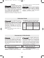
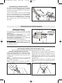
CHANGING THE COLLET
The bit flutes are sharp and
should be handled with
caution.
The 1/8" collet is used with 1/8" diameter
bits, the 1/4" collet is used with 1/4" diameter
bits and the 5/32" collet is used with 5/32"
diameter bits.
To change collets, loosen the collet nut with
the included wrench and remove the bit.
Continue to loosen and unscrew the collet
nut until you can remove it from the tool.
Remove the collet and replace it with the
other (Fig. 3).
(Each collet is double-ended, and either end
is acceptable to use.) By hand, re-tighten
the collet nut around the collet in a clockwise
direction. You are now ready to insert a new
bit as instructed in Installing Bits (Fig. 4).
-7-
Disconnect the plug from
the power source before
making any assembly, adjustments or
changing accessories. Such preventive safety
measures reduce the risk of starting the tool
accidentally. Make certain that the collet nut is
securely tightened before turning the tool on.
REMOVING, INSTALLING, AND
ADJUSTING THE DEPTH GUIDE
In order to remove the depth guide from the
tool, turn the thumb screw counter-clockwise
until you can remove it from the tool. The
depth guide should then pull freely from the tool.
To reattach the depth guide, line up the slot in
the depth guide with the threaded hole in the
metal housing and re-install the thumb screw
by rotating it clockwise until tight. Be careful
not to cross-thread the thumb screw.
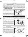
The depth guide allows you to control the
depth of cut. Loosen the thumb screw by
turning it counter-clockwise until the depth
guide can slide freely on the metal housing.
For bits with a guide point (Drywall XBITS
™,
Guidepoint
®
and Window & Door Zip
®
bits)
make sure that the entire guide point tip will
extend 1/8” beyond the material thickness
(Fig. 2). For standard point drywall Zip
®
bits,
make sure that the fluted end of the bit
extends 1/8” beyond the material thickness.
Assembly
!
WARNING
!
WARNING
INSTALLING BITS
The bits are held by a collet system. Use either
the 1/8", 1/4" or 5/32" collet depending on the
size of the bit shank.
Depress and hold the shaft-lock in and rotate
the collet nut and shaft until the shaft-lock
engages and holds the shaft.
Use the included wrench to loosen the nut by
rotating it counter-clockwise (Fig 4). Remove
the old bit (if there is one) and insert the new
bit as far as possible. Re-engage the shaft
lock and tighten the nut by rotating it
clockwise by hand, then with the wrench until
the bit is held securely.
SHAFT
LOCK
COLLET
COLLET
NUT
1/8"
THUMB SCREW
FIG. 2
OUTPUT SHAFT
1/8"
COLLET NUT
SHAFT
LOCK
FIG. 3
FIG. 4
RZ 2610955525 10-07 10/11/07 8:19 AM Page 7

INSTALLING THE SUPPORT STRAP
With the Velcro
®
facing up, thread the end of
the strap with the Rotozip
®
logo around the
post near the cord as shown.
Thread the other end through the slot near
the front of the tool. Fold the front flap over
first (1), then fold the end with the Rotozip
®
logo (2) as shown. Press firmly to ensure the
strap is secured.
-8-
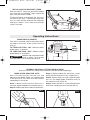
BUMP SWITCH (ON/OFF)
This tool is switched “ON” by the bump switch
located on the back of the motor housing
(Fig. 6).
TO TURN THE TOOL “ON” slide the switch
button up or “1” position.
TO TURN THE TOOL “OFF” slide the switch
button down or “0” position.
Hold the tool with both hands
while starting, since torque
from the motor can cause the tool to twist.
!
WARNING
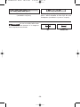
Operating Instructions
MAKE A FEW PRACTICE CUTS
After installing the Bit into the tool and
adjusting your depth guide, you should make
a few practice cuts with the tool before
attempting an actual job.
Step 1: Make certain that the collet nut is
securely tightened before turning the tool on.
Step 2: Hold the tool firmly and turn the tool on.
Step 3: While holding the tool firmly, insert
the bit into the material at a 45
° angle (Fig. 7).
Step 4: Slowly bring it to a 90
° angle to begin
the cut. The depth guide should be flush to
the material surface (Fig. 8).
Step 5: Steer the tool in a clockwise direction
with slow, steady pressure to make the cut.
1
2
0
1
GENERAL DRYWALL CUTTING INSTRUCTIONS
(See next section for cutting electrical boxes and door/window openings)
FIG. 5
FIG. 6
FIG. 7
FIG. 8
BUMP
SWITCH
(ON/OFF)
RZ 2610955525 10-07 10/11/07 8:19 AM Page 8

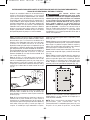
Step 1: Be certain that the box or fixture is
firmly mounted and all wires or other
obstructions around the opening are pushed
back out of the way. The bit uses the outer
edge of the box or fixture as a guide, so it is
important that there is nothing in the way
which can prevent it from guiding completely
around the opening. For the purposes of this
instruction manual, the procedure discussed
will be to make a cut-out around a standard 2
1/8" x 3 3/4" electrical box.
Step 2: Slide switch to turn the tool on. While
holding the Drywall Router firmly with both
hands, plunge the bit through the mark you
made. Then guide the bit to the right until you
feel and hear the bit touch the inside edge of
the box (Fig. 9).
Step 3: Pull the bit out far enough to slip it
over the edge of the box so it is now against
the outside of the box (Fig. 10).
Step 4: While keeping the bit in contact with
the outside of the box move the tool counter
clockwise while applying light inward and
upward pressure until you feel and hear it
come to the corner. As you round the corner
apply light pressure left and downward (Fig. 10).
Step 5: While moving slowly and continuously
along the top contour you will feel the bit come
to the next corner. Round the corner and
apply light down and inward pressure until the
bottom corner is reached (Fig. 10).
Step 6: Move the bit right and upward
maintaining light continuous pressure toward
the box (Fig. 10).
Step 7: Round the right bottom corner and
begin moving the bit upward while applying
light pressure left toward the box until you
meet initial upward cut. Push Drywall Router
switch to off (Fig. 10).
Step 8: The completed box, executed quickly,
neatly, and in a fraction of the time taken by
other methods.
NOTE: These step-by-step instructions are
generalized to acquaint you with the Drywall
Router’s operation. After some practice, you
may develop a technique with which you are
more comfortable. However, you must always
begin the cut somewhat centrally, and MOVE
-9-
After assembling the bit into the tool as
described earlier, it will be necessary to review
the instructions provided below and make some
practice cut-outs with this tool before attempting
an actual job. The best method is to take some
scrap pieces and nail or screw them in place
over wall studs which have an electrical box or
other feature in place. A few such exercises will
give you the necessary practice to make clean,
professional cutouts around whatever is behind
the drywall you are installing.
Do not attempt to use this
tool to make cut-outs
around any fixture or opening which has
live electrical wires, or on any wall which
may have live electrical wiring behind it, as
the bit could conduct current to the tool,
creating an electrocution hazard for the
operator. Shut off breakers or remove fuses to
disconnect the circuit. Always hold the tool by
its thermoplastic housing, and always wear
eye protection when operating this device.
!
WARNING
INSTRUCTIONS FOR CREATING CUT-OUTS IN DRYWALL
FOR OUTLETS, CAN LIGHTS, WINDOWS, AND DOORS
3
4
5
6
7
FIG. 9
FIG. 10
RZ 2610955525 10-07 10/11/07 8:19 AM Page 9

-10-
Service
Preventive maintenance
performed by unauthorized
personnel may result in misplacing of
internal wires and components which could
cause serious hazard. We recommend that
all tool service be performed by a
Rotozip/Bosch Factory Service Center or
Authorized Rotozip/Bosch Service Station.
TOOL LUBRICATION
Your Rotozip tool has been properly lubricated
and is ready to use.
BEARINGS
After about 75-100 hours of operation, or at
every second brush change, the bearings
should be replaced at Bosch Factory Service
Center or Authorized Bosch Service Station.
Bearings which become noisy (due to heavy
load or very abrasive material cutting) should
be replaced at once to avoid overheating or
motor failure.
CARBON BRUSHES
The brushes and commutator in your tool have
been engineered for many hours of
dependable service. To maintain peak motor
efficiency, we recommend the brushes be
examined every two to six months. Only use
genuine Rotozip replacement brushes
specially designed for your tool.
If your tool runs sporadically, loses power,
makes unusual noises, or runs at a reduced
speed, check the brushes. Continuing to use
the tool in this condition will permanently
damage the motor.
Do not attempt to operate the tool with
broken, missing, or loose brush doors. If
the brush doors or brush door screws become
lost or damaged, please contact Rotozip
Customer Service for replacement parts.
To Replace the Brushes
1. Disconnect the tool from the power supply.
2. Each door is held in place by a screw.
Using a screwdriver, loosen the screw by
rotating it counter-clockwise (Fig. 1). Be careful
not to lose the screw.
3. Using your fingernail, pry the brush door
loose and remove it from the tool.
4. In order to remove the brush, you must pull
back the spring that is holding the brush in
place. Using needle nose pliers, carefully pull
back the end of the brush spring and place it to
the side of the brush near the hole for the
brush door screw. Once the spring has been
moved, you can remove the brush by pulling
on the brush wire connector (Fig. 11). Be
careful not to bump the brush spring or
damage the brush wire connector. Make a
note of which side of the tool the brush was
removed.
5. Check both brushes. The brushes in your
Drywall Router will not wear at the same rate.
If either brush is less than 3/16" (4.8mm) long
or the worn end of the brush is rough or pitted,
replace both brushes. Place the new brush in
the brush holder, making sure the brush wire is
securely connected to its terminal inside the
tool. Fold the brush wire away from the screw
hole as shown. Place the end of the spring into
its original position.
6. Replace the brush doors. Be careful not to
over-tighten the brush door screw.
Maintenance
!
WARNING
THE DRYWALL ROUTER ONLY COUNTER-
CLOCKWISE to take advantage of the
“hugging” action of the bit along the contours
of the template. Remember to use a smooth,
continuous motion. The exception to this rule
applies to cutting window and door openings.
Since you are tracing around the inside of the
framing members, move the bit clockwise to
take advantage of the bits “hugging” action.
FIG. 11
SPRING
BRUSH WIRE
CONNECTOR
BRUSH
WIRE
SCREW HOLE
RZ 2610955525 10-07 10/11/07 8:19 AM Page 10

-11-
Cleaning
To avoid accidents always
disconnect the tool from
the power supply before cleaning or
performing any maintenance. The tool may
be cleaned most effectively with compressed
dry air. Always wear safety goggles when
cleaning tools with compressed air.
Ventilation openings and switch levers must
be kept clean and free of foreign matter. Do
not attempt to clean by inserting pointed
objects through openings.
Certain cleaning agents
and solvents damage
plastic parts. Some of these are: gasoline,
carbon tetrachloride, chlorinated cleaning
solvents, ammonia and household
detergents that contain ammonia.
!
WARNING
!
CAUTION
If an extension cord is
necessary, a cord with
adequate size conductors that is capable
of carrying the current necessary for your
tool must be used. This will prevent
excessive voltage drop, loss of power or
overheating. Grounded tools must use 3-
wire extension cords that have 3-prong plugs
and receptacles.
NOTE: The smaller the gauge number, the
heavier the cord.
RECOMMENDED SIZES OF EXTENSION CORDS
120 VOLT ALTERNATING CURRENT TOOL
Extension Cords
Tool’s
Ampere
Rating
Cord Size in A.W.G.
Wire Sizes in mm
2
3-6
6-8
8-10
10-12
12-16
18 16 16 14 0.75 0.75 1.5 2.5
18 16 14 12 0.75 1.0 2.5 4.0
18 16 14 12 0.75 1.0 2.5 4.0
16 16 14 12 1.0 2.5 4.0 —
14 12 — — — — — —
25 50 100 150 15 30 60 120
Cord Length in Feet Cord Length in Meters
!
WARNING
Use only recommended
accessories with this tool.
Do not use metal cutting bits, router bits, or
non-approved accessories with this product.
See list of approved accessories in manual.
Accessories that may be suitable for one
tool, may become hazardous when used on
another tool.
For drywall cutting only.
Your DR1 Drywall Router
was designed specifically for cutting drywall.
Rotozip offers products to cut a wide range
of materials. If your cutting requirements
extend to materials beyond drywall, please
contact your local Rotozip retailer, Rotozip
Customer Service, or www.Rotozip.com for
further information on our products.
!
WARNING
Accessories & Attachments
!
WARNING
Drywall XBITS™ (Ø5/32”)
XB-DW2 / XB-DW10 Drywall XBITS™ with
Guidepoint (available in 2-pack or 10-pack)
Drywall Zip
®
Bits (Ø1/8”)
GP10 / GP20 Guidepoint Zip
®
Bit (available
in 10-pack or 20-pack)
RZ 2610955525 10-07 10/11/07 8:19 AM Page 11

-12-
ZB10 Drywall Zip
®
Bit
(available in 10-pack)
Drywall Zip
®
Bits (Ø1/4”)
WD1 / WD10 Window & Door Zip
®
Bit with
Guidepoint (available in 1-pack or 10-pack)
Do not use WD1/WD10 bits
that measure 3" in length or
have a tip like the one shown.
!
WARNING
OK DO NOT USE
RZ 2610955525 10-07 10/11/07 8:19 AM Page 12

-13-
Veuillez lire et comprendre toutes les consignes. Si on n'observe pas toutes les
consignes décrites ci-dessous, il y a risque de choc électrique, d’incendie et/ou
de blessures corporelles graves. Dans toutes les mises en garde ci-dessous, le terme « outil électroportatif »
se rapporte à des outils branchés sur le secteur (avec fil) ou à des outils alimentés par piles (sans fil).
CONSERVEZ CES CONSIGNES
Consignes générales de sécurité
AVERTISSEMENT
!
Sécurité du lieu de travail
Maintenez le lieu de travail propre et bien éclairé.
Les risques d’accident sont plus élevés quand on
travaille dans un endroit encombré ou sombre.
N’utilisez pas d’outils électroportatifs dans des
atmosphères explosives, comme par exemple en
présence de gaz, de poussières ou de liquides
inflammables. Les outils électroportatifs produisent
des étincelles qui risquent d’enflammer les poussières
ou les vapeurs.
Éloignez les enfants et les visiteurs quand vous vous
servez d’un outil électroportatif. Vous risquez une
perte de contrôle si on vous distrait.
Sécurité électrique
Les fiches des outils électroportatifs doivent
correspondre à la prise. Il ne faut absolument jamais
modifier la fiche. N’utilisez pas d’adaptateur de prise
avec des outils électroportatifs munis d’une fiche de
terre. Le risque de choc électrique est moindre si on
utilise une fiche non modifiée sur une prise qui lui
correspond.
Évitez tout contact du corps avec des surfaces reliées
à la terre tels que tuyaux, radiateurs, gazinières ou
réfrigérateurs. Le risque de choc électrique augmente
si votre corps est relié à la terre.
N’exposez pas les outils électroportatifs à la pluie ou
à l’humidité. Si de l’eau pénètre dans un outil
électroportatif, le risque de choc électrique augmente.
Ne maltraitez pas le cordon. Ne vous en servez
jamais pour transporter l’outil électroportatif, pour le
tirer ou pour le débrancher. Éloignez le cordon de la
chaleur, des huiles, des arêtes coupantes ou des
pièces mobiles. Les cordons abîmés ou emmêlés
augmentent les risques de choc électrique.
Si vous utilisez un outil électroportatif à l’extérieur,
employez une rallonge conçue pour l’extérieur. Ces
rallonges sont faites pour l’extérieur et réduisent le
risque de choc électrique.
N’utilisez pas un outil conçu uniquement pour le C.A.
sur une alimentation en C.C. Même si l’outil semble
fonctionner, les composants électriques d’un outil prévu
pour le C.A. tomberont probablement en panne et
risquent de créer un danger pour l’utilisateur.
S’il est nécessaire d’utiliser l’outil dans un lieu
humide, il faut l’alimenter par l’intermédiaire d’un
disjoncteur différentiel de fuite à la terre (DDFT).
L’emploi d’un DDFT et de dispositifs de protection
personnelle tels que gants et chaussures d’électricien
en caoutchouc améliorent votre sécurité personnelle.
Sécurité personnelle
Restez concentré, faites attention à ce que vous
faites, et servez-vous de votre bon sens lorsque vous
utilisez un outil électroportatif. N'employez pas
d’outils électroportatifs quand vous êtes fatigué ou
sous l’emprise de drogues, d’alcool ou de
médicaments. Quand on utilise des outils
électroportatifs, il suffit d’un moment d’inattention pour
causer des blessures corporelles graves.
Utilisez des équipements de sécurité. Portez toujours
une protection oculaire. Si les conditions le
demandent, il faut porter un masque à poussière, des
chaussures de sécurité antidérapantes, un casque de
chantier ou une protection auditive pour réduire le
risque de blessure corporelle.
Évitez les démarrages intempestifs. Assurez-vous
que l’interrupteur est en position arrêt (OFF) avant de
brancher l’outil. Transporter un outil électroportatif
avec le doigt sur la gâchette ou le brancher quand
l’interrupteur est en position “marche” (ON) présente
des risques d’accident.
Enlevez toutes les clés de réglage avant de mettre
l’outil électroportatif en marche. Si on laisse une clé
sur une pièce tournante de l’outil électroportatif, il y a
risque de blessure corporelle.
Ne vous penchez pas. Conservez toujours une bonne
assise et un bon équilibre. Ceci vous permettra de
mieux maîtriser l’outil électroportatif dans des situations
inattendues.
Habillez-vous de manière appropriée. Ne portez pas
de vêtements amples ou de bijoux. Attachez les
cheveux longs. N’approchez pas les cheveux, les
vêtements ou les gants des pièces en mouvement.
Les vêtements amples, les bijoux ou les cheveux longs
risquent d’être happés par les pièces en mouvement.
Si l’outil est muni de dispositifs permettant le
raccordement d’un système d’aspiration et de
collecte des poussières, assurez-vous que ces
dispositifs sont raccordés et utilisés correctement.
L’utilisation de ces dispositifs peut permettre de réduire
les dangers liés à la poussière.
Maintenez les poignées sèches et exemptes d’huile et
de graisse. On ne pas maîtriser un outil électroportatif
en toute sécurité quand on a les mains glissantes.
RZ 2610955525 10-07 10/11/07 8:19 AM Page 13

-14-
Consignes de sécurité concernant les défonceuses pour cloisons sèches
Tenez l'outil par les surfaces isolées de prise en
exécutant une opération lorsque l'outil de coupe peut
venir en contact avec des fils cachés ou son propre
cordon. Le contact avec un fil sous tension rendra les
parties métalliques exposées de l'outil sous tension et
causera des secousses électriques à l'opérateur.
Utilisez des brides ou d’autres moyens pratiques de
brider ou de supporter la pièce sur une plate-forme
stable. Tenir la pièce à la main ou contre le corps est
instable et risque de résulter en une perte de contrôle.
Pour couper dans des murs existants ou autres endroits
aveugles pouvant dissimuler des fils électriques,
débranchez tous les fusibles ou les disjoncteurs
alimentant ce lieu de travail.
Assurez-vous toujours que la surface de travail est
exempte de clous et autres objets étrangers. La coupe
dans un clou peut faire sauter l’embout et l'outil, et ainsi
abîmer l’embout.
Ne tenez jamais le matériau d'une main et l'outil de
l'autre lorsque vous en faites usage. Ne placez jamais
les mains sous la surface de coupe ou à proximité de
celle-ci. Il est plus sûr de cramponner le matériau et de
guider l'outil des deux mains.
Ne posez jamais le matériau sur des surfaces dures
telles que le béton, la pierre, etc. L’embout de coupe
en saillie peut faire sauter l'outil.
Utilisation et entretien des outils
électroportatifs
Ne forcez pas sur l’outil électroportatif. Utilisez l’outil
électroportatif qui convient à la tâche à effectuer.
L’outil qui convient à la tâche fait un meilleur travail et
est plus sûr à la vitesse pour lequel il a été conçu.
Ne vous servez pas de l’outil électroportatif si son
interrupteur ne parvient pas à le mettre en marche ou
à l’arrêter. Tout outil électroportatif qui ne peut pas
être commandé par son interrupteur est dangereux et
doit être réparé.
Débranchez la fiche de la prise ou enlevez le bloc-
piles de l’outil électroportatif avant tout réglage,
changement d’accessoires ou avant de ranger l’outil
électroportatif. De telles mesures de sécurité
préventive réduisent le risque de démarrage intempestif
de l’outil électroportatif.
Rangez les outils électroportatifs dont vous ne vous
servez pas hors de portée des enfants et ne permettez
pas à des personnes qui ne connaissent pas l’outil
électroportatif ou qui ignorent ces consignes de s’en
servir. Les outils électroportatifs sont dangereux dans
les mains d’utilisateurs inexpérimentés.
Entretenez les outils électroportatifs. Vérifiez que les
pièces mobiles sont alignées correctement et ne
coincent pas. Vérifiez qu’il n’y a pas de pièces
cassées ou d’autre circonstance qui risquent
d’affecter le fonctionnement de l’outil électroportatif.
Si l’outil est abîmé, faites-le réparer avant de
l’utiliser. De nombreux accidents sont causés par des
outils électroportatifs mal entretenus.
Maintenez les outils coupants affûtés et propres. Les
outils coupants entretenus correctement et dotés de
bords tranchants affûtés sont moins susceptibles de
coincer et sont plus faciles à maîtriser.
Utilisez l’outil électroportatif, les accessoires, les
embouts etc. selon ces consignes et de la manière
prévue pour chaque type particulier d’outil
électroportatif en tenant compte des conditions de
travail et de la tâche à accomplir. L'emploi d’outils
électroportatifs pour des tâches différentes de celles
pour lesquelles ils ont été prévus peut résulter en une
situation dangereuse.
Utilisez des brides ou d’autres moyens pratiques de
brider ou de supporter la pièce sur une plate-forme
stable. Tenir la pièce à la main ou contre le corps est
instable et risque de résulter en une perte de contrôle.
Entretien
Faites réparer votre outil électroportatif par un agent
de service qualifié n’utilisant que des pièces de
rechange identiques. Ceci assure que la sécurité de
l’outil électroportatif est préservée.
Créez un agenda d’entretien périodique pour votre
outil. Quand vous nettoyez un outil, faites attention
de n’en démonter aucune pièce car il est toujours
possible de mal remonter ou de pincer les fils
internes ou de remonter incorrectement les ressorts
de rappel des capots de protection. Certains agents de
nettoyage tels que l’essence, le tétrachlorure de
carbone, l’ammoniaque, etc. risquent d’abîmer les
plastiques.
Risque de blessure pour l'utilisateur. Le cordon
d'alimentation électrique ne doit être réparé que par un
Centre de service usine de Bosch ou par une Station
service agréée de Bosch.
CONSERVEZ CES INSTRUCTIONS
RZ 2610955525 10-07 10/11/07 8:19 AM Page 14

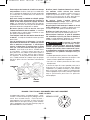
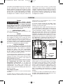
Le modèle DR01-1100TL, est équipé de la fiche « Twist-
To-Lock » ci-contre. N’utilisez qu’une rallonge à trois fils
munie d’un raccord femelle « Twist-To-Lock »
correspondant à une extrémité et d’une fiche trois
broches dont une avec prise de terre à l’autre extrémité.
(Voir le paragraphe sur la Sécurité Électrique, page 14
pour information sur la mise à la terre.)
-15-
Portez toujours des lunettes de sécurité et un masque
anti-poussières. N'utilisez l'outil qu'à un endroit bien
aéré. L'utilisation de dispositifs de sécurité personnelle
et le travail dans un environnement sûr réduisent les
risques de blessures.
Après avoir changé les embouts ou effectué quelque
réglage que ce soit, assurez-vous que l'écrou de la
douille et tout autre dispositif de réglage sont bien
serrés. Un dispositif de réglage lâche peut bouger
soudainement et causer ainsi une perte de contrôle avec
projection violente des composants en rotation.
Ne mettez jamais l'outil en marche alors que
l’embout est enfoncée dans le matériau. Le tranchant
de l’embout peut se coincer dans le matériau et vous
faire perdre le contrôle du couteau.
Tenez toujours l'outil des deux mains durant la mise
en marche. Le couple de réaction du moteur peut faire
tordre l'outil.
Lors du toupillage ou du découpage, le sens de
déplacement du tranchant de l’embout qui pénètre
dans le matériau est important. Il faut toujours
pousser l’embout dans le matériau dans le même
sens que celui du bord tranchant qui quitte le
matériau. Avec l’outil vu du dessus, l’embout tourne
en sens horaire. Si l’outil se trouve entre vous et la
pièce, poussez-le vers la droite. Si par contre la pièce se
trouve entre vous et l’outil, poussez alors ce dernier
vers la gauche. Si vous poussez l’outil dans le mauvais
sens, le bord tranchant de l’embout risque de grimper
hors de la pièce et de tirer l’outil dans la direction de
l’avance.
N'utilisez jamais d’embouts émoussés ou abîmés.
Les embouts affilés doivent être maniés
soigneusement. Les embouts abîmés peuvent se
rompre brusquement durant l'usage. Les embouts
émoussés nécessitent plus de force pour pousser
l'outil, causant éventuellement un bris de l’embout.
Ne touchez jamais l’embout durant ou
immédiatement après l'usage. Après usage, l’embout
est trop chaud pour être touché à main nue.
Ne posez jamais l'outil avant que le moteur ne se soit
arrêté complètement. L’embout en rotation peut saisir
la surface et vous faire perdre le contrôle de l'outil.
N'utilisez pas l'outil pour percer. Cet outil n'est pas
destiné à être utilisé avec des embouts de perceuse.
Utilisez toujours l'outil avec le guide de profondeur
fixé solidement et placé à plat contre le matériau à
couper. Le guide positionné solidement sur le matériau
améliore la stabilité et le contrôle de votre outil.
Les travaux à la machine
tel que ponçage, sciage,
meulage, perçage et autres travaux du bâtiment
peuvent créer des poussières contenant des produits
chimiques qui sont des causes reconnues de cancer,
de malformation congénitale ou d’autres problèmes
reproductifs. Ces produits chimiques sont, par
exemple :
• Le plomb provenant des peintures à base de plomb,
• Les cristaux de silices provenant des briques et du
ciment et d’autres produits de maçonnerie, et
• L’arsenic et le chrome provenant des bois traités
chimiquement.
Le niveau de risque dû à cette exposition varie avec la
fréquence de ces types de travaux. Pour réduire
l’exposition à ces produits chimiques, il faut travailler
dans un lieu bien ventilé et porter un équipement de
sécurité approprié tel que certains masques à poussière
conçus spécialement pour filtrer les particules
microscopiques.
AVERTISSEMENT
!
EMBOUT
PIÈCE
SENS DE
L’AVANCE
COMMENCEZ
ICI
RACCORD « TWIST-TO-LOCK » POUR MODÈLE DR01-1100TL UNIQUEMENT
20 AMP, 125 VOLTS
NEMA L5-20P
RZ 2610955525 10-07 10/11/07 8:19 AM Page 15

-16-
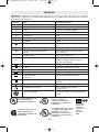
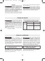
Symboles
IMPORTANT : Certains des symboles suivants peuvent être utilisés sur votre outil. Veuillez les étudier et
apprendre leur signification. Une interprétation appropriée de ces symboles vous permettra d'utiliser l'outil de
façon plus efficace et plus sûre.
Symbole Nom Désignation/Explication
V Volts Tension (potentielle)
A Ampères Courant
Hz Hertz Fréquence (cycles par seconde)
W Watt Puissance
kg Kilogrammes Poids
min Minutes Temps
s Secondes Temps
Diamètre Taille des embouts de perceuse, meules,
etc.
n
0
Vitesse à vide Vitesse de rotation, à vide
.../min Tours ou mouvement alternatif par Tours, coups, vitesse en surface, orbites,
minute etc., par minute
0 Position d'arrêt Vitesse zéro, couple zéro ...
1, 2, 3, ... Réglages du sélecteur Réglages de vitesse, de couple ou de
l, ll, lll, ... position. Un nombre plus élevé signifie
une vitesse plus grande.
Sélecteur variable à l'infini avec arrêt La vitesse augmente depuis le réglage 0
Flèche Action dans la direction de la flèche
Courant alternatif Type ou caractéristique du courant
Courant continu Type ou caractéristique du courant
Courant alternatif Type ou caractéristique du courant
ou continu
Construction classe II Désigne des outils construits avec double
isolation
Borne de terre Borne de mise à la terre
Symbole d'avertissement Alerte l'utilisateur aux messages
d'avertissement.
Sceau Ni-Cad RBRC Désigne le programme de recyclage des piles
Ni-Cad.
0
Ce symbole signifie que cet
outil est approuvé par
Underwriters Laboratories.
Ce symbole signifie que cet
outil est approuvé par
l'Association canadienne de
normalisation.
Ce symbole signifie que
cet outil est approuvé
conformément aux normes
canadiennes par Underwriters
Laboratories.
Ce symbole
signifie que
cet outil se
conforme aux
normes
mexicaines
NOM.
Ce symbole signifie que cet outil
est approuvé par Underwriters
Laboratories et qu’il a été
homologué selon les normes
canadiennes par Underwriters
Laboratories.
RZ 2610955525 10-07 10/11/07 8:19 AM Page 16

-17-
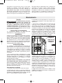
Description fonctionnelle et spécifications
Débranchez la fiche de la prise de courant avant d'effectuer quelque assemblage
ou réglage que ce soit ou de changer les accessoires. Ces mesures de sécurité
préventive réduisent le risque d'une mise en marche accidentelle de l'outil.
REMARQUE : Pour spécifications de l'outil, reportez-vous à la plaque signalétique de votre outil.
AVERTISSEMENT
!
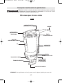
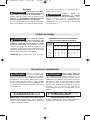
FIG. 1
Défonceuse pour cloisons sèches
GUIDE DE PROFONDEUR
BLOCAGE DE L'ARBRE
ÉVENTS
D'ADMISSION D'AIR
INTERRUPTEUR
MARCHE/ARRÊT À
PERCUSSION
COURROIE DE
PRÉHENSION
ÉVENTS
D'ÉCHAPPEMENT D'AIR
VIS À SERRAGE À
MAIN DU GUIDE
DE PROFONDEUR
ÉCROU DE LA DOUILLE
PORTE DU
COMPARTIMENT À BALAIS
VIS
COMPARTIMENT DE
RANGEMENT DE LA CLÉ
CORDON
RZ 2610955525 10-07 10/11/07 8:19 AM Page 17

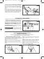
INSTALLATION DES EMBOUTS
Les embouts sont maintenus en place par un système
de douille. Utilisez la douille de 1/8 po, de 1/4 po ou de
5/32 po en fonction de la tige de l'embout.
Appuyez sur le mécanisme de blocage de l'arbre et
maintenez-le enfoncé, puis tournez l'écrou de la douille
et l'arbre jusqu'à ce que le mécanisme de blocage de
l'arbre s'enclenche et maintienne l'arbre en place.
Utilisez la clé jointe pour desserrer l'écrou en le
tournant dans le sens antihoraire (Fig. 4). Retirez
l'ancien embout (s'il y en a un) et insérez le nouvel
embout aussi profondément que possible.
Réenclenchez le mécanisme de blocage de l'arbre et
serrez l'écrou en le tournant dans le sens horaire,
d'abord à la main, puis avec la clé, jusqu'à ce que
l'embout soit solidement maintenu en place.
CHANGEMENT DE LA DOUILLE
Les cannelures des embouts
sont très affûtées et doivent
être manipulées avec précaution.
La douille de 1/8 po est utilisée avec des embouts de
1/8 po de diamètre, la douille de 1/4 po est utilisée avec
des embouts de 1/4 po de diamètre et la douille de 5/32
po est utilisée avec des embouts de 5/32 po de
diamètre.
Pour changer la douille, desserrez l'écrou de la douille
au moyen de la clé jointe et retirez l'embout. Continuez
à desserrer et à dévisser l'écrou de la douille jusqu'à ce
que vous puissiez le retirer de l'outil. Retirez la douille et
remplacez-la par l'autre douille (Fig. 3).
(Chaque douille a une double extrémité, et n'importe
laquelle de ces extrémités peut être utilisée.) Serrez à
nouveau à la main l'écrou de la douille autour de la
douille dans le sens horaire. Vous êtes maintenant prêt
à insérer un nouvel ambout conformément aux
instructions de la rubrique consacrée à l'installation des
embouts (Fig. 4).
-18-
Débranchez la fiche de la
prise de courant avant
d'effectuer quelque assemblage ou réglage que ce
soit ou de changer les accessoires. Ces mesures de
sécurité préventive réduisent le risque d'une mise en
marche accidentelle de l'outil. Assurez-vous que l'écrou
de douille est serré solidement avant de mettre l'outil en
marche.
RETRAIT, INSTALLATION ET RÉGLAGE
DU GUIDE DE PROFONDEUR
Pour retirer le guide de profondeur de l'outil, tournez la
vis à serrage à main dans le sens antihoraire jusqu'à ce
que vous puissiez le retirer de l'outil. Le guide de
profondeur devrait alors sortir librement de l'outil.
Pour rattacher le guide de profondeur, alignez la fente
dans le guide de profondeur avec le trou fileté dans le
logement en métal et réinstallez la vis à serrage à main
en la tournant dans le sens horaire jusqu'à ce qu'elle
soit serrée à fond. Faites attention de ne pas déformer le
filetage de la vis à serrage à main.
Le guide de profondeur vous permet de contrôler la
profondeur de la coupe. Desserrez la vis à serrage à
main en la tournant dans le sens antihoraire jusqu'à ce
que le guide de profondeur puisse glisser librement sur
le logement en métal. Dans le cas des embouts ayant
une pointe de guidage (embouts XBITS™ pour cloisons
sèches, embouts Guidepoint
®
et Window & Door Zip
®
),
assurez-vous que l'ensemble de la pointe de guidage
dépasse l'épaisseur du matériau de 1/8 po (Fig. 2).
Dans le cas des embouts Zip
®
pour cloisons sèches à
pointe standard, assurez-vous que l'extrémité cannelée
de l'embout dépasse l'épaisseur du matériau de 1/8 po.
AVERTISSEMENT
!
Assemblage
AVERTISSEMENT
!
3mm
VIS À SERRAGE
FIG. 2
BLOCAGE
DE L'ARBRE
DOUILLE
ÉCROU
DE LA
DOUILLE
ARBRE DE SORTIE
FIG. 3
3mm
ÉCROU DE LA DOUILLE
BLOCAGE
DE L'ARBRE
FIG. 4
RZ 2610955525 10-07 10/11/07 8:19 AM Page 18

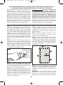
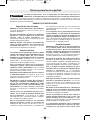
EXÉCUTEZ QUELQUES COUPES DE PRATIQUE
Après avoir installé l'embout dans l'outil et ajusté votre
guide de profondeur, exécutez quelques coupes de
pratique avant d'effectuer des travaux réels.
Étape 1 : assurez-vous que l'écrou de la douille est
solidement serré avant de mettre l'outil en marche.
Étape 2 : tenez fermement l'outil et mettez celui-ci en
marche.
Étape 3 : tout en continuant à tenir fermement l'outil,
insérez l'embout dans le matériau à un angle de 45°
(Fig. 7).
Étape 4 : inclinez lentement l'outil à un angle de 90°
pour commencer la coupe. Le guide de profondeur
doit être au ras de la surface du matériau (Fig. 8).
Étape 5 : orientez l'outil pour couper dans le sens
horaire en faisant pression lentement, mais
fermement, pour effectuer la coupe.
INTERRUPTEUR MARCHE/ARRÊT À PERCUSSION
Cet outil est mis en marche au moyen de l'interrupteur
à percussion situé à l'arrière du bâti du moteur (Fig. 6).
POUR METTRE L'OUTIL EN MARCHE, faites glisser
l'interrupteur vers le haut, c. à d. dans la position « 1 ».
POUR ARRÊTER L'OUTIL, faites glisser l'interrupteur
vers le bas, c. à d. dans la position « 0 ».
Tenez l'outil des deux
mains durant la mise en
marche étant donné que le couple du moteur peut
faire tordre l'outil.
AVERTISSEMENT
!
INSTALLATION DE LA COURROIE DE PRÉHENSION
Orientez la bande Velcro
®
vers le haut, puis enfilez le
bout de la courroie comportant le logo Rotozip
®
autour de la tige située près du cordon comme
illustré.
Enfilez l'autre bout à travers la fente située près du
devant de l'outil. Repliez le rabat du devant en premier
(1), puis pliez le bout comportant le logo Rotozip
®
(2)
comme illustré. Appuyez fermement pour vous
assurer que la courroie est solidement installée.
-19-
1
2
FIG. 5
Consignes de fonctionnement
0
1
FIG. 6
INTERRUPTEUR
MARCHE/ARRÊT
À PERCUSSION
INSTRUCTIONS GÉNÉRALES CONCERNANT LA COUPE
DANS DES CLOISONS SÈCHES
(Référez-vous à la section suivante en ce qui concerne la coupe d'ouvertures
pour des boîtiers électriques et des portes/fenêtres)
FIG. 7
FIG. 8
RZ 2610955525 10-07 10/11/07 8:19 AM Page 19

-20-
Étape 1 : assurez-vous que le boîtier ou tout autre objet
concerné est monté solidement et que tous les fils et
autres obstructions possibles autour de l'ouverture
sont repoussés à un endroit où ils ne vous gêneront
pas. Comme l'embout utilise le bord extérieur du boîtier
et de l'autre objet éventuel comme guide, il est
important qu'il n'y ait rien qui fasse obstacle et vous
empêche de guider l'outil complètement autour de
l'ouverture. Aux fins de ce mode d'emploi, la procédure
discutée consistera à découper une partie de la cloison
autour d'un boîtier électrique standard de 2 1/8 po x 3
3/4 po.
Étape 2 : faites glisser l'interrupteur pour mettre l'outil
en marche. Tout en tenant fermement la défonceuse
pour cloisons sèches avec les deux mains, insérez
l'embout à travers la marque que vous avez faite. Puis
guidez l'embout vers la droite jusqu'à ce que vous
sentiez et entendiez l'entrée en contact de l'embout
avec le bord intérieur du boîtier (Fig. 9).
Étape 3 : tirez sur l'embout afin qu'elle soit
suffisamment éloignée pour pouvoir la faire glisser au-
dessus du bord du boîtier, de telle sorte qu'elle soit en
contact avec l'extérieur du boîtier (Fig. 10).
Étape 4 : tout en maintenant l'embout en contact avec
l'extérieur du boîtier, déplacez l'outil dans le sens
antihoraire et appliquez une légère pression vers
l'intérieur et vers le haut jusqu'à ce que vous sentiez et
entendiez le contact avec le coin. Pendant que vous
tournez le coin, appliquez une légère pression vers la
gauche et vers le bas (Fig. 10).
Étape 5 : avancez lentement et uniformément le long
du contour supérieur jusqu'à ce que vous sentiez
l'embout atteindre le coin suivant. Faites le tour du coin
et appliquez une légère pression vers le bas et vers
l'intérieur jusqu'à ce que l'embout atteigne la coin
inférieur (Fig. 10).
Étape 6 : déplacez l'embout vers la droite et vers le
haut tout en maintenant une légère pression
ininterrompue vers le boîtier (Fig. 10).
Étape 7 : faites le tour du coin inférieur droit et
commencez à faire avancer l'embout vers le haut tout
en appliquant une légère pression vers la gauche dans
le sens du boîtier jusqu'au moment où vous ferez
contact avec la coupe vers le haut initiale. Faites glisser
l'interrupteur de la défonceuse pour cloisons sèches en
position d'arrêt (Fig. 10).
Étape 8 : le trou autour du boîtier est maintenant
complet. Il a été exécuté rapidement, proprement et en
une fraction du temps nécessaire si l'on utilise d'autres
méthodes.
REMARQUE : ces instructions pas à pas sont
généralisées de manière à vous permettre de vous
familiariser avec le fonctionnement de la défonceuse
pour cloisons sèches. Après avoir pratiqué un peu plus
Après avoir monté l'embout sur l'outil comme cela a été
décrit plus haut, il sera nécessaire de lire les
instructions fournies ci-dessous et de faire quelques
coupes de pratique avec cet outil avant d'effectuer des
travaux réels. La meilleure méthode consiste à prendre
quelques morceaux de bois mis au rebut et de les
clouer ou visser en place sur des montants de mur qui
ont un boîtier électrique ou un autre objet en place.
Quelques exercices de ce genre vous donneront la
pratique nécessaire pour faire des coupes nettes,
d'aspect professionnel, autour de ce qui existe derrière
la cloison sèche que vous êtes en train d'installer.
Ne tentez pas d'utiliser cet
outil pour effectuer des
découpages autour de tout appareil ou ouverture qui
possède des fils électriques sous tension, ou sur
tout mur derrière lequel se trouvent des fils
électriques sous tension, car l'embout pourrait
conduire le courant à l'outil, créant ainsi un danger
d'électrocution pour l'opérateur. Mettez les
disjoncteurs à l'arrêt ou retirez les fusibles pour
sectionner le circuit. Tenez toujours l'outil par son
boîtier thermoplastique, et portez toujours des
lunettes de protection en utilisant ce dispositif.
INSTRUCTIONS POUR DÉCOUPER DES CLOISONS SÈCHES AFIN DE CRÉER DES OUVERTURES POUR
DES PRISES DE COURANT, DES BOÎTIERS ÉLECTRIQUES, DES FENÊTRES ET DES PORTES
AVERTISSEMENT
!
FIG. 9
3
4
5
6
7
FIG. 10
RZ 2610955525 10-07 10/11/07 8:19 AM Page 20
La page est en cours de chargement...
La page est en cours de chargement...
La page est en cours de chargement...
La page est en cours de chargement...
La page est en cours de chargement...
La page est en cours de chargement...
La page est en cours de chargement...
La page est en cours de chargement...
La page est en cours de chargement...
La page est en cours de chargement...
La page est en cours de chargement...
La page est en cours de chargement...
La page est en cours de chargement...
La page est en cours de chargement...
La page est en cours de chargement...
La page est en cours de chargement...
-
 1
1
-
 2
2
-
 3
3
-
 4
4
-
 5
5
-
 6
6
-
 7
7
-
 8
8
-
 9
9
-
 10
10
-
 11
11
-
 12
12
-
 13
13
-
 14
14
-
 15
15
-
 16
16
-
 17
17
-
 18
18
-
 19
19
-
 20
20
-
 21
21
-
 22
22
-
 23
23
-
 24
24
-
 25
25
-
 26
26
-
 27
27
-
 28
28
-
 29
29
-
 30
30
-
 31
31
-
 32
32
-
 33
33
-
 34
34
-
 35
35
-
 36
36


RotoZip DR1 Manuel utilisateur
- Catégorie
- Outils électroportatifs
- Taper
- Manuel utilisateur
- Ce manuel convient également à
dans d''autres langues
- English: RotoZip DR1 User manual
- español: RotoZip DR1 Manual de usuario


