GE GSD2100VBB Manuel utilisateur
- Catégorie
- Lave-vaisselle
- Taper
- Manuel utilisateur

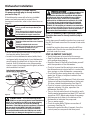
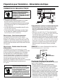
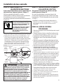
BEFORE YOU BEGIN
Read these instructions completely and
carefully.
Installation Instructions
Built-In Dishwasher
If you have questions, call 800.GE.CARES (800.432.2737) or visit our website at: GEAppliances.com
In Canada, call 1.800.561.3344 or visit www.GEAppliances.ca
IMPORTANT – The dishwasher MUST be
installed to allow for future removal from the
enclosure if service is required.
If you received a damaged dishwasher, you should
immediately contact your dealer or builder.
Your dishwasher is a water heating appliance.
Optional Accessories – See the Owner’s Manual for
available custom panel kits.
FOR YOUR SAFETY
Read and observe all CAUTIONS and WARNINGS
shown throughout these instructions. While
performing installations described in this booklet,
gloves and safety glasses should be worn.
READ CAREFULLY.
KEEP THESE INSTRUCTIONS.
IMPORTANT – Observe all governing codes
and ordinances.
• Note to Installer – Be sure to leave these
instructions for the consumer and local
inspector’s use.
• Note to Consumer – Keep these instructions with
your Owner’s Manual for future reference.
• Skill Level – Installation of this dishwasher
requires basic mechanical, electrical and
plumbing skills. Proper installation is the
responsibility of the installer. Product failure
due to improper installation is not covered
under the GE Appliance Warranty. See warranty
information.
• Completion Time – 1 to 3 Hours. New installations
require more time than replacement installations.
31-31570 04-16 GE

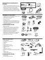
TOOLS YOU WILL NEED:
• Safety glasses
• 1/4" and 5/16" nutdrivers
• Flashlight
• Gloves
• Adjustable wrench (6”)
• Phillips-head screwdriver
• Measuring tape
• Level
• Carpenter’s square
• Bucket to catch water when flushing water
line
• Tubing cutter
• 15/16" socket wrench
FOR NEW INSTALLATIONS:
• Hole saw set
• Drill and appropriate bits
PARTS SUPPLIED IN INSTALLATION
PACKAGE:
• Two 8-18 x 5/8" Phillips-head wood screws
• Junction box cover and #10 hex head screw
• Drain hose (78" long) and hose clamp
• Cord protector (Power Cord Models Only)
• Conversion leads (Power Cord Models Only)
• Literature, product samples and/or coupons
MATERIALS YOU WILL NEED:
• WX09X70910 or WX09X70911 power cord if
applicable to your installation
• UL-Listed wire nuts (3)
• Thread seal tape
• 90° elbow (¾” hose internal thread on one
end, opposite end sized to fit water supply)
• GPF65 Side-mount bracket kit for use with
granite countertops
FOR NEW INSTALLATIONS:
• Electrical cable
• Water line–3/8" minimum copper tubing
(including ferrule and compression nut)
• Strain relief for electrical connection
• Hand shut-off valve (recommended)
• Air gap for drain hose, if required
• Waste tee for house plumbing, if applicable
• GPF10S drain hose (10' long), if needed
• Screw-type hose clamps
Hose Clamp
78" Drain Hose
Thread
Seal Tape
3 Wire Nuts
Hot Water Line–3/8"
Minimum Copper
Tubing
Electrical Cable
or WR09X70910
or WX09X70911
Power Cord
Air
Gap
Screw-Type
Hose Clamps
Strain Relief
Phillips-Head
Screwdriver
Level
Carpenter’s
Square
Measuring Tape
Safety Glasses
Flashlight
Gloves
Hole Saw Set
Drill and
Bits
6KXW2ȹ
Valve
1/4" and 5/16" Nutdrivers
Adjustable
Wrench
Tubing
Cutter
GPF65 Side-Mount
Bracket Kit
#8
Phillips-Head
Wood Screws
5/8" long
Screw Kit
#10
Hex Head
Junction Box Screw
1/2" long
Junction Box Cover
Cord Protector
(Power Cord Models Only)
Conversion Leads
(Power Cord Models Only)
15/16"
Socket Wrench
Bucket
Optional 10'
Drain Hose
GPF10S
Waste Tee
Coupler for
optional drain
hose
90° Elbow
2

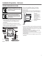
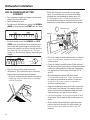
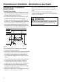
Installation Preparation – Enclosure
PREPARE DISHWASHER ENCLOSURE
Figure A
To reduce the risk of shock, fire, or injury
to persons, the installer must ensure that
the dishwasher is completely enclosed at
the time of installation.
• The rough cabinet opening must have a minimum
width and depth of 24" and height of 34-1/2"
IURPWKHÀRRUWRWKHXQGHUVLGHRIWKH
countertop.
• The back wall should be free of pipes or wires.
• Adjacent cabinets should be square and plumb to
HQVXUHDJRRG¿W5HIHUWR)LJXUH$
• For a corner installation, allow 2” minimum
clearance between the dishwasher and the
adjacent wall.
• Provide at least 27” in front of the dishwasher to
allow the dishwasher door to open fully. Refer to
Figure B.
0DNHVXUHWKHÀRRULVOHYHOLQVLGHWKHRSHQLQJDQG
HYHQZLWKWKH¿QLVKHGÀRRURIWKHNLWFKHQ7KLVZLOO
facilitate removal of the dishwasher at a later date
for service, if needed.
• The dishwasher must be installed no more than
10 feet from sink for proper drainage.
• The dishwasher must be fully enclosed on the top,
sides and back.
• The dishwasher must not support any part of the
enclosure.
Figure B
2" Minimum
Countertop
Dishwasher
27" Minimum
Clearances:
In a corner installation,
provide at least 2"
clearance between the
dishwasher and the
adjacent cabinet, wall or
other appliance.
Provide at least 27" of
clearance in front of the
dishwasher.
Para reducir el riesgo de choque, incendio
o lesión a personas, el instalador se
debe cerciorar de que la lavadora esté
completamente cerrada en el momento
de la instalación.
ADVERTENCIA
WARNING
3

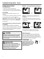
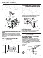
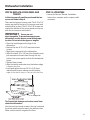
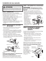
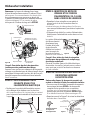
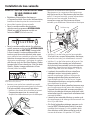
METHOD 1 – Air Gap with Waste Tee or Disposer
Disposer Installation
METHOD 2 – High Drain Loop with Waste Tee
or Disposer
Provide a method to attach the drain hose to the
underside of countertop. Attachment will be made
in a later step.
Waste Tee Installation
Figure C
Waste Tee Installation Disposer Installation
Figure D
Install waste tee or disposer and the air gap
according to the manufacturer’s instructions.
Cabinet Preparation
Drill a 1-1/2" diameter hole in the cabinet wall
within the shaded area shown in Figure A for the
drain hose. Make sure there are no sharp edges.
The drain hose will be passed through this hole and
connected to the drain in a later step.
IMPORTANT – When
connecting the drain line to a
disposer, check to be sure that
drain plug has been removed.
Dishwasher will not drain if
plug is left in place.
32"
Min.
18"
Min.
32"
Min.
18"
Min.
CAUTION
An air gap MUST BE USED if the drain hose is connected
to waste tee or disposer lower than 18" above the floor
level. Failure to provide the proper drain connection
height with an air gap or 32" minimum, high drain loop
will result in improper draining of the dishwasher, which
may cause damage.
Installation Preparation – Drain
Remove
Drain
Plug
PREPARE DRAIN PLUMBING
Drain Requirements
• Follow local codes and ordinances.
• Drain hose must not exceed 10 feet in length.
• A high drain loop or air gap is required. See below.
Drain Method
The type of drain installation depends on the
following:
• Do local codes or ordinances require an air gap?
,VZDVWHWHHOHVVWKDQDERYHWKHÀRRU"
If the answer to either question is YES, an air gap
(Method 1) must be used. If both answers are NO,
either an air gap or a high drain loop (Method 2)
may be used.
Special consideration for a dishwasher installed
on a pedestal
lf the dishwasher is installed on an elevated
platform, a high drain loop of at least 32" above the
platform must be provided in addition to the air gap
requirement determined above. This is necessary
for proper drain performance.
PRECAUCIÓN
SE DEBE USAR un espacio de aire si la manguera
de drenaje se conecta a la T de desechos o al triturador
menos de 18" por encima del nivel del piso. No disponer
la altura correcta de la conexión del drenaje con
un espacio de aire o 32" de mínimo, una curva alta
de drenaje resultará en un drenaje incorrecto
de la lavadora, lo que pude causar daños.
4

The improper connection of the equipment-
grounding conductor can result in electric
shock. Check with a qualified electrician or
service representative if you are in doubt
that the appliance is properly grounded.
Do not modify the plug provided with the
appliance; if it will not fit the outlet, have
a proper outlet installed by a qualified
technician.
WARNING
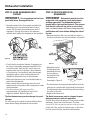
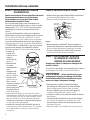
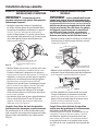
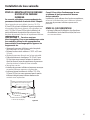
Cabinet Preparation and Wire Routing
• The wiring may enter the opening from either side,
rear or floor within the shaded area illustrated
above in Figure E and defined in Figure A.
• Cut a 1-1/2" maximum diameter hole to insert the
electrical cable. Permanent wiring connections
may pass through the same hole as the drain
hose and hot water line, if convenient. Hole edges
must be smooth and rounded. If the cabinet wall is
metal, the hole edge must be covered with a cord
protector.
NOTE: Power cords with plug must pass through a
separate hole.
PREPARE ELECTRICAL WIRING
Electrical Requirements
• This appliance must be supplied with 120V, 60 Hz.,
and connected to an individual properly grounded
branch circuit, protected by a 15- or 20-ampere
circuit breaker or time-delay fuse.
• Wiring must be 2 wire with ground.
• If the electrical supply does not meet the above
requirements, call a licensed electrician before
proceeding.
Grounding Instructions – Permanent Connection
This appliance must be connected to a grounded-
metal, permanent wiring system, or an equipment-
grounding conductor must be run with the circuit
conductors and be connected to the equipment-
grounding terminal or lead on the appliance.
Grounding Instructions – Power Cord Models
This appliance must be grounded. In the event of a
malfunction or breakdown, grounding will reduce
the risk of electric shock by providing a path of
least resistance for electric current. This appliance
is equipped with a cord having an equipment-
grounding conductor and a grounding plug. The
plug must be plugged into an appropriate outlet
that is installed and grounded in accordance with
all local codes and ordinances.
White
18"
6"
24"
from Wall
3"
from
Cabinet
Alternate
Receptacle
Location
Ground
Black
1-1/2" Dia. Hole (Max.)
18"
6"
Receptacle
Location
Area
Figure E
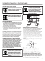
Installation Preparation – Electrical Supply
FOR PERSONAL SAFETY: Remove house fuse
or open circuit breaker before beginning
installation. Do not use an extension cord
or adapter plug with this appliance.
Electrical Connection to Dishwasher
Electrical connection is on the right front of
dishwasher.
• For permanent connections, the cable must
be routed as shown in Figure E. The cable must
extend a minimum of 24" from the rear wall.
• For power cord connections, install a 3-prong
grounding-type receptacle in the adjacent cabinet
rear wall, between 6" and 18" from the opening, 6"
to 18" above the floor as shown in Figure E.
Hole Diameter
1-1/2" Maximum
Cord
Protector
(Provided
with Power
Cord Models Only)
Metal Cabinet Wall
PARA SEGURIDAD PERSONAL: Retire el
fusible de la casa o abra el interruptor de
circuitos antes de empezar la instalación.
No use un cable de extensión o enchufe
adaptador con este aparato.
La conexión incorrecta del conductor
de conexión a tierra del equipo puede
resultar en choque eléctrico. Consulte con
un electricista calificado o representante
de servicio si tiene dudas de la conexión
a tierra del aparato. No modifique el
enchufe que se suministra con el aparato;
si no calza en el tomacorrientes, haga
que un técnico calificado le instale un
tomacorrientes adecuado.
ADVERTENCIA
WARNING
WARNING
ADVERTENCIA
5

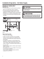
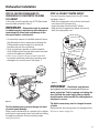
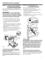
Installation Preparation – Hot Water Supply
PREPARE HOT WATER SUPPLY
Hot Water Line
• The line may enter from either side, rear or floor
within the shaded area shown in Figure F.
• The line may pass through the same hole as
the electrical cable and drain hose, or cut an
additional 1-1/2" diameter hole to accommodate
the water line. If a power cord with plug is used,
the water line must not pass through the power
cord hole.
Figure F
Water Line Connection
• Turn off the water supply.
• Install a hand shut-off valve in an accessible
location, such as under the sink. (Optional, but
strongly recommended and may be required by
local codes.)
• The water connection is on the left side of the
dishwasher. Install the hot water inlet line, using
3/8" or larger copper tubing. Route the line as
shown in Figure F and extend forward at least 19"
from rear wall.
• Adjust the water heater to deliver water between
120°F and 150°F.
• Flush water line to clean out debris. Use a bucket
to catch water and debris.
• The hot water supply line pressure must be
between 20 and 120 PSI.
6"
5"
5"
4"
Cabinet Face
Shut-off
Valve
4"
2" From Floor
19" From Wall
2"
From
Cabinet
1-1/2" Dia.
Hole
Hot
CAUTION
The hot water supply line pressure must be at least 20 PSI.
Lower pressures could cause the water valve to leak and
cause water damage.
PRECAUCIÓN
La línea de presión del suministro de agua caliente debe
ser al menos 20 PSI. Presiones inferiores podrían causar
que la válvula del agua gotee y causar daños por agua.
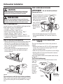
6

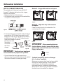
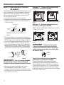
STEP 2: CHECK DOOR BALANCE
• With the dishwasher on the wood base, check the
door balance by opening and closing the door.
• The door is properly balanced if it gently drops
from a 1/2 open position and does not rise from
the full open position.
• If necessary, increase or decrease tension as
shown. Latch the door and adjust springs to
correct balance.
Dishwasher Installation
CAUTION
Do not remove the wood base until you are ready to
install the dishwasher. The dishwasher will tip over
when the door is opened if the base is removed.
STEP 4: REMOVE ACCESS PANEL AND
TOEKICK
The top mounting holes in the access panel are
slotted.
• Remove the lower two 10-16 x 3/8" sheet metal
screws. Do not remove the two top 8-32 x 1/4"
machine thread screws.
• Slide the access panel to the left as far as it will go.
• Gently pull the access panel forward to remove
it from the top screws.
Set access panel, toekick and screws aside for use
in Step 20.
Tip: Prevent tub damage.
Remove only the 3/8" sheet metal screws in this
step. This
will help
prevent a
mix- up with
the 1/4"
machine
thread
screws in
Step 20.
Figure H
STEP 1: PREPARATION
Locate the items in the installation package and set
them aside for use in the listed steps.
• Screw kit – Steps 5 or 16 and 13
• Junction box cover – Steps 5 or 16
• Drain hose and drain hose clamp – Step 7
• Owners’ Manual – Steps 18 and 21
• Product Samples and/or coupons – Step 21
• Conversion leads (Factory-equipped power cord
models only) – Appendix
STEP 3: REMOVE WOOD BASE
IMPORTANT – Do not kick off wood base!
Damage will occur.
• Move the dishwasher close to the installation
location and lay it on its back.
• Remove the four leveling
legs from the underside of
the wood base
with a 15/16"
socket wrench.
• Remove and
discard wood
base.
Tip: Avoid service calls for door balance problems.
Make sure the spring end is fully engaged in a frame
hole and the spring link is fully seated in the hinge
arm.
• Screw leveling legs back into the dishwasher
frame, approximately 3/4" from the frame, as
shown.
Insert Hook Through
Hole from Inside of Frame
Link fully seated
in hinge arm
Figure I
PRECAUCIÓN
No retire la base de madera hasta que esté listo para
instalar la lavadora de platos. Cuando la puerta se abra,
la lavadora de platos se inclinará si la base se retira.
Figure G
7

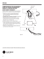
• Install strain relief in the junction box bracket.
• Insert the power cord through the strain relief and
tighten.
• Make sure black, white and green dishwasher
wires are threaded through the small hole in the
junction box bracket.
• Connect power cord white (or ribbed) to
dishwasher white, black (or smooth) to dishwasher
black and ground to dishwasher green wire. Use
UL-listed wire nuts of appropriate size.
• Install junction box cover using the #10 hex-head
screw. Be sure wires are not pinched under the
cover.
STEP 5: INSTALL POWER CORD
Skip this step if the dishwasher will be
permanently connected to the house electrical
system or has a factory-installed power cord.
In this step you will need the junction box cover and
the #10 x 1/2" hex-head screw from the screw kit
set aside in Step 1.
The power cord and connections must comply
with the National Electrical Code, Section 422 and/
or local codes and ordinances. Maximum power
cord length is 6 feet. Power Cord Kit WX09X70910
or WX09X70911, available for purchase from
an authorized GE appliance dealer, meets these
requirements.
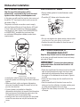
Dishwasher Installation
STEP 7:
INSTALL DRAIN HOSE TO
DISHWASHER DRAIN PORT
Skip this step if drain hose has been preinstalled.
In this step you will need the drain hose and clamp
set aside in Step 1.
IMPORTANT – Prevent drain hose damage
and possible leaks. Be careful not to nick or cut
the drain hose.
• Route the small end of the drain hose from the left
side of the dishwasher through the strain relief
attached to the dishwasher frame and toward
the center of the dishwasher as shown in Figures
L and M.
• Place the hose clamp over the small end of the
drain hose.
• Push the small end of the drain hose over the
drain port on the collection chamber, making sure
it is fully seated against the hose stop.
• Tighten the hose clamp to at least 15 inch-pounds
of torque.
Figure K
STEP 6: INSTALL 90° ELBOW
• Ensure rubber gasket is located between valve
and elbow.
• Thead the 90° elbow onto the water valve.
• Do not over tighten the elbow; water valve bracket
FRXOGEHQGRUWKHYDOYH¿WWLQJFRXOGEUHDN
• Position the end of the elbow to face the rear of
the dishwasher.
Water
Valve
Bracket
90° Elbow
Fill
Hose
Gasket
Junction
Box
Bracket
Ground White Black
Cover
Strain Relief and
Dishwasher Wires
8

Bracket
Attachment
Screws
(2 Each
Side)
Side-
Mounting
Brackets
Tub Frame
Skip this step if the underside of countertop is
wood or woodlike material.
• Purchase and install the GPF65 side-mount
bracket kit if the underside of counter is granite
or a similar material that will not accept wood
screws. The GPF65 kit is available from authorized
GE appliance dealers.
• Refer to Figure P and follow the instructions
included in
the kit.
Note: The drain hose supplied with the dishwasher
is approximately 78" long. If a longer hose is
needed, a 10-foot-long hose may be purchased
from an authorized GE appliance dealer. The
10-foot-long hose is part number GPF10S.
STEP 8: POSITION WATER LINE AND
POWER SUPPLY
• Position the water supply line and house wiring
RQWKHÀRRURIWKHRSHQLQJWRDYRLGLQWHUIHUHQFH
with the base of the dishwasher and components
under the dishwasher.
Figure N
STEP 9: INSERT DRAIN HOSE AND POWER
CORD, IF USED, THROUGH CABINET
• Upright the dishwasher and position it in front of
the cabinet opening.
• Insert the drain hose into the hole previously
drilled in the cabinet wall.
• If a power cord is used, guide the end of the cord
through a separate hole cut for the power cord.
The power cord should be routed directly to the rear
of the junction box, avoiding contact with the door
spring and other dishwasher components.
Water
Line
Power
Supply
Water
Power
Drain
Figure O
STEP 10: INSTALL OPTIONAL GPF65 SIDE
MOUNT BRACKETS
Figure P
Dishwasher Installation
Tip: Avoid unnecessary service charges for no fill,
drain or noise concerns.
Position utility lines so they do not interfere with
anything under or behind the dishwasher.
Optional
Side-Mount
Bracket Kit
Drain Hose
D
o not use
this port if
present
Collection Chamber
Drain Port
Hose Clamp
Hose Stop
Tip: Avoid unnecessary service charges for drain
issues.
Make sure the drain hose connection is leak-free
and the hose is routed through the strain relief so
it will not kink when the dishwasher is installed into
the cabinet.
Figure M
Strain
Relief
Drain Hose
Figure L
9

Dishwasher Installation
Turn Legs
to Adjust
Figure S
STEP 11: SLIDE DISHWASHER INTO
CABINET
IMPORTANT – Do not push against the front
panel with knees. Damage will occur.
• Grasp the sides of the front panel and slide the
dishwasher into the opening a few inches at
a time. Pull the drain hose and power cord, if
equipped, through the holes in the adjacent
cabinet while sliding the dishwasher into position.
• Check the tub insulation blanket, if equipped, to
be sure it is smoothly wrapped around the tub.
It should not be “bunched up” and it must not
interfere with the door springs. If the insulation
is “bunched up” or interfering with the springs,
straighten and re-center the blanket prior to
sliding the dishwasher into its final position.
• Make sure the drain hose is not kinked under or
behind the dishwasher.
• Make certain the house wiring, drain line and
water line do not interfere with components under
the dishwasher.
7KHGLVKZDVKHUWXEÀDQJHVKRXOGEH
approximately 3/4" behind the face of the
adjacent cabinet. Refer to Figure R.
Tip: Avoid unnecessary service charges for panel
damage.
Do not press on the center of panel with hands or
knees when sliding dishwasher into position.
Figure Q
STEP 12: POSITION AND LEVEL
DISHWASHER
IMPORTANT – Dishwasher must be level for
proper dish rack operation, wash performance
and door operation. The dishwasher must be
leveled left to right and front to back. This ensures
that the dish racks will not roll in or out on their
RZQFLUFXODWLRQZDWHUZLOOÀRZWRWKHSXPSLQOHW
and the door will close without hitting the side of
the tub.
•
Remove the lower dish rack and place a level on
the door and lower rack track as shown in Figure R.
Figure R
•
Adjust the level of
the dishwasher by
individually turning
the four legs on
the bottom of the
dishwasher as
illustrated in Figure S.
• The dishwasher is properly leveled when the level
indicator is centered left to right and front to back.
The dishwasher door should close without hitting
the sides of the tub.
• Replace the lower rack.
Tip: Avoid unnecessary service charges for poor
wash performance and rack operation.
Pull the dish racks half way out. They should remain
stationary. Open and close the door. The door
VKRXOG¿WLQWKHWXERSHQLQJZLWKRXWKLWWLQJWKHVLGH
of the tub. If the racks roll on their own, or the door
hits the side of the tub, relevel the dishwasher.
10

STEP 13: FASTEN DISHWASHER TO
UNDERSIDE OF COUNTERTOP OR SIDES
OF CABINET
In this step you will need the two 5/8" Phillips-head
wood screws set aside in Step 1.
IMPORTANT – Dishwasher must be centered
in cabinet opening. Interference with cabinets or
countertop will cause leaks and damage to the
door panel and/or control panel.
• If countertop is wood or woodlike material, fasten
the dishwasher to the countertop by driving the
Phillips head screws through the countertop
brackets and into the countertop.
• If the countertop is granite or similar material,
drive Phillips screws through side mount brackets
and into the adjacent cabinets.
0DNHVXUHVFUHZVDUHGULYHQVWUDLJKWDQGÀXVK
to prevent interference with door operation and
damage to the control panel. See Figure T.
Figure T
Dishwasher Installation
STEP 14: CONNECT WATER SUPPLY
Connect the water supply line to the 90° elbow
installed in Step 6.
• Slide the compression nut and then the ferrule
over the end of the water line.
• Insert the water line into the 90° elbow.
• Slide the ferrule against the elbow and secure
with the compression nut.
Figure U
IMPORTANT – Check to be sure the door
VSULQJGRHVQRWUXERUFRQWDFWWKH¿OOKRVHRU
water supply line. Test by opening and closing the
door. Reroute the water supply lines or slightly
bend the water valve bracket if a rubbing noise or
interference occurs.
Tip: Avoid unnecessary service charges for noise
or leaks.
Make sure the door spring does not rub against the
¿OOKRVHRUZDWHUVXSSO\OLQH
Tip: Avoid unnecessary service charges for leaks
or control panel damage.
Make sure the dishwasher is centered in the cabinet
and the door opens and closes freely without hitting
the adjacent cabinets. Drive mounting screws
VWUDLJKWDQGÀXVK
90° Elbow
Hot Water
Supply Line
Fill Hose
Water Valve Bracket
Ferrule
Hot Water
Supply Line
Compression Nut
90°
Elbow
11

Dishwasher Installation
Waste Tee Installation
Method 1 – Air gap with waste tee or disposer
Disposer Installation
Waste Tee Installation
Method 2 – “High drain loop” with waste tee
or disposer
Fasten the drain hose to the underside of the
countertop with a hanger.
Disposer Installation
Figure X
Figure Y
IMPORTANT – When connecting the drain
line to a disposer, check to be sure that the drain
plug has been removed. Dishwasher will not drain
if plug is left in place.
STEP 15: CONNECT DRAIN LINE
The molded end of the drain hose will fit 5/8"
through 1" diameter inlet ports on the air gap,
waste tee or disposer.
• Determine the size of the inlet port
• Cut the drain hose connector on the marked line,
LIUHTXLUHGWR¿WWKHLQOHWSRUW
• If a longer drain hose is required, and you did not
purchase the GPF10S drain hose, add up to 42"
length, for a total of 120" (10 feet), to the factory-
installed hose. Use 5/8" or 7/8" inside diameter
hose and a coupler to connect
the two hose ends.
Secure the
connection
with hose
clamps.
Figure V
IMPORTANT – Total drain hose length must
not exceed 10 feet for proper drain operation.
• Connect drain line to air gap, waste tee, or
disposer using the previously determined method.
Secure the hose with a screw-type clamp.
Tip: Avoid unnecessary service call charges
for a “no drain” complaint.
Make sure any excess drain hose has been pulled
through the cabinet opening. This will prevent
excess hose in the dishwasher cavity from
becoming kinked or crushed by the dishwasher.
Make sure the disposer plug has been removed if
the drain hose is connected to a disposer.
Remove
Drain
Plug
Figure W
12

Dishwasher Installation
If house wiring is not 2-wire with a ground
wire, a ground must be provided by the
installer.
When house wiring is aluminum, be sure
to use UL listed anti-oxidant compound
and aluminum-to-copper connectors.
STEP 17: INSTALL JUNCTION BOX COVER
If junction box cover is already installed, skip to
Step 18.
In this step you will need the junction box cover and
the #10 hex-head screw from the screw kit set aside
in Step 1.
• Install the junction box cover using the #10 hex-
head screw. Check to be sure that wires are not
pinched under the cover.
STEP 18: PRETEST CHECKLIST
• Verify that power is turned off at the source.
• Open the dishwasher door and remove all foam
and cardboard packaging.
• Read the Owner’s Manual to familiarize yourself
with the operation of the dishwasher.
• Check to be sure that the wiring is secure under
the dishwasher and not pinched or in contact with
door springs or other dishwasher components.
• Check that the door spring does not contact the
water line, fill hose, or adjacent cabinets. See
Steps 13 and 14.
• Pull lower rack about halfway out. Check to be sure
it does not roll back into dishwasher or further out.
If it does, relevel the dishwasher. See Step 12.
• Check to be sure control panel does not touch
adjacent cabinets. If it does, reposition the
dishwasher. See Step 13.
• Turn on the hot water faucet at the sink to verify
that the water temperature is at least 120°F and not
more than 150°F. Adjust water heater if necessary.
• Add two quarts of water to the bottom of the
dishwasher to lubricate the pump seal.
• Turn on water supply.
• Check for water leaks. Tighten connections if
necessary. See Step 14.
• Remove the protective film, if present, from the
control panel, access panel and door panel.
STEP 16: CONNECT POWER SUPPLY
If a power cord with plug is already installed,
proceed to Step 17.
If the dishwasher came with a factory-installed
power cord and you want to convert it to a
permanent connection, refer to the instructions on
page 16.
• Secure house wiring to the back of the junction
box bracket with a strain relief.
• Locate the three dishwasher wires (white, black
and green) with stripped ends. Insert dishwasher
wires through the small hole in the junction box
bracket. Use UL-listed wire nuts of appropriate
size to connect incoming ground to green, white to
white and black to black.
Si el cableado de la casa no es de 2 cables
con un cable de conexión a tierra, el
instalador debe suministrar una conexión
a tierra.
Cuando el cableado de la casa es en
aluminio, cerciórese de usar un compuesto
anti-oxidante aprobado por UL y un
compuesto de aluminio a cobre.
WARNING
ADVERTENCIA
CAUTION - The Current Sensing Module
(CSM) is a current-sensing device located behind the
toekick. It is possible for the CSM to trip during shipping.
If that occurs, the installer can reset the CSM during
installation. If the CSM trips after the appliance is installed
and energized, DO NOT RESET THE CSM. CALL SERVICE.
Failure to have a qualified service technician examine
an installed dishwasher after the CSM trips can result in
personal injury or damage to the appliance or property.
PRECAUCIÓN - El Módulo de Detección
Actualizada (Current Sensing Module, CSM) es
un dispositivo de detección actualizada ubicado detrás
del tope de pie. Existe la posibilidad de que el CSM se
caiga durante el envío. Si esto ocurre, el instalador
puede reiniciar el CSM durante la instalación. Si el CSM
se cae luego de que el electrodoméstico fue instalado
y conectado, NO REINICIE EL CSM. LLAME AL SERVICIO
TÉCNICO. Si el lavavajillas ya instalado no es examinado
SRUXQWpFQLFRFDOL¿FDGRGHOVHUYLFLRWpFQLFROXHJRGHXQD
caída del CSM, se podrán producir lesiones personales o
daños sobre el electrodoméstico o la propiedad.
Figure Z
13

Dishwasher Installation
– Check the electrical connection to the water
valve. The red electrical connector should be
plugged into the dishwasher water valve. If it
LVQRWSOXJJHGLQWXUQRȺHOHFWULFDOSRZHUWR
the dishwasher. Plug the red connector into the
dish washer water valve and then restore power.
• Check for leaks under the dishwasher. If a leak is
IRXQGWXUQRȺSRZHUWLJKWHQFRQQHFWLRQVDQG
restore power.
• Check for leaks around the door. A leak around
the door could be caused by the dishwasher door
rubbing or hitting adjacent cabinets. Reposition
the dishwasher if necessary. See Steps 11, 12
and 13.
• Most dishwasher models will drain about
PLQXWHVDIWHUWKH¿UVW¿OO&KHFNWKHGUDLQOLQH
for leaks when dishwasher drains. If leaks are
IRXQGWXUQRȺSRZHUFRUUHFWDVQHFHVVDU\
and then restore power.
• Open the dishwasher door and make sure most
of the water has drained. If the water does not
drain, check to be sure disposer plug has been
removed and/or air gap is free of debris.
/HWWKHGLVKZDVKHUUXQWKURXJKDQRWKHU¿OODQG
drain cycle. Check again to be sure there are no
leaks.
• At the end of the second drain, push the reset
pad on electronic models. For dial models, un-
ODWFKWKHGRRUDQGURWDWHWKHGLDOWRWKH´2Ⱥµ
position.
STEP 19: DISHWASHER WET TEST
CHECKLIST
• Turn on power supply or if power cord is used,
plug it into the wall outlet.
• Latch dishwasher door.
• For electronic dishwashers, select the NORMAL
WASH cycle and press the START pad one time.
• Check to be sure that water enters the
dishwasher. This could take up to 4 minutes.
If water does not enter the dishwasher:
– Check to be sure that the water is turned on.
²/LJKWO\WDSWKHÀRRGÀRDWFRYHUWRGLVORGJH
DVWXFNÀRRGÀRDW
Flood Float
Cover
• For dial models, press the NORMAL and HOT
START pads, if model has them, and then turn
the control dial just enough to start the dish-
washer. Be careful not to turn the dial past the
¿UVWZDWHU¿OO'LDOVKRXOGSRLQWWR´+RW6WDUW
Option” or “Hot Prewash Option” depending on
model.
Hi- T emp
W ash
Heavy
W ash
P ots
& P ans
Cycles
Normal
W ash
Hot
S ta r t
Hea t ed
D r y
Hot Start
Option
S ta r t Delay
(HRS)
Cycle
on
Off
1
3
2
4
6
5
Pla t e W armer
(Heated D r y On)
Rinse Only
(Heated D r y Of f )
S ta r t
Light W ash
R eset
H
EAVY
W
ASH
P
OTS
&
PANS
Cycles
N
ORMAL
W
ASH
C
HINA
C
RYSTAL
R
INSE
O
NLY
S
TAR T
R
ESET
C
LEAN
C
LEAN
HI T
EMP
R
INSE
HI T
EMP
W
ASH
H
EATED
D
RY
D
ELAY
H
OURS
L
OCK
(2 T
IMES
)
248
Appearance varies by model. Not all models have push buttons.
Red Connector
14

Figure AA
Dishwasher Installation
STEP 20: REPLACE ACCESS PANEL AND
TOEKICK
In this step you will need the panels and the two
screws set aside in Step 4.
There are two types of screws used. The 8-32 x 1/4"
screws are used at the top of the access panel and
should still be in place. The 10-16 x 3/8" screws are
used at the bottom of the access panel and secure
both the access panel and toekick.
IMPORTANT – Screws are not
interchangeable. To prevent damage to your
dishwasher, use the proper screw in the proper
location. Do not mix screw types or lengths.
• Place the toekick against the legs of the
dishwasher.
• Remove the two 8-32 x 1/4" machine-thread
screws.
• Align the access panel to the dishwasher.
• Select the two 8-32 x 1/4" machine-thread screws
just removed and insert them through the top
holes in the access panel and into the dishwasher
frame.
• Tighten these screws.
• Align the toekick and make sure the bottom edge
LVDJDLQVWWKHÀRRU
• Insert and tighten the two 10-16 x 3/8" sheet
metal thread screws, making sure the bottom
HGJHRIWKHWRHNLFNVWD\VLQFRQWDFWZLWKWKHÀRRU
STEP 21: LITERATURE
• Leave the Owners’ Manual, Installation
Instructions, samples and/or coupons with
consumer.
Tip: Prevent tub damage and reduce sound from
under the dishwasher.
Use the machine-thread screws in the top holes and
the sheet metal-thread screws in the bottom holes.
Make sure the toekick is against the floor.
15

Appendix
CONVERTING DISHWASHER WITH
FACTORY- EQUIPPED POWER CORD TO A
PERMANENT CONNECTION
This procedure requires the conversion leads set
aside in Step 1.
• Make sure the power cord for the dishwasher is
unplugged from the wall outlet.
• Remove screw from junction box cover and
remove cover if present.
• Disconnect the three power cord conductors from
the dishwasher harness. See Figure BB.
• Remove and discard the power cord.
• Connect the conversion harness (included with
dishwasher) to the dishwasher harness by
connecting like-colored wires. See Figure CC.
• Return to Step 16 in these instructions to complete
the conversion.
Figure CC
Figure BB
Conversion Harness
SPECIFICATIONS SUBJECT TO CHANGE WITHOUT NOTICE
Appliance Park
Louisville, KY 40225
16

Instructions d’installation
Lave-vaisselle encastré
Pour toute question, composez le 1.800.561.3344 ou visitez notre site Web :
www.electromenagersge.ca
IMPORTANT – Le lave-vaisselle DOIT être
installé de manière à ce qu’il puisse être sorti
de son emplacement si des réparations sont
nécessaires.
Si le lave-vaisselle que vous avez reçu est
endommagé, communiquez immédiatement avec
votre détaillant ou l’entrepreneur en construction.
9RWUHODYHYDLVVHOOHHVWXQDSSDUHLOTXLFKDXȺHO·HDX
Accessoires facultatifs – Reportez-vous au Manuel
d’utilisation pour connaître les ensembles pour
SDQQHDXGpFRUDWLISHUVRQQDOLVpRȺHUWV
POUR VOTRE SÉCURITÉ
Veuillez lire et observer toutes les mises en garde
(ATTENTION et AVERTISSEMENT) données dans les
présentes directives. Pour effectuer l’installation
décrite dans les présentes directives, il faut porter
des gants et des lunettes de sécurité.
VEUILLEZ LIRE ATTENTIVEMENT ET
CONSERVER CES DIRECTIVES.
IMPORTANT – Observez tous les codes
et ordonnances en vigueur.
• Note à l’installateur – Veuillez laisser les présentes
directives au consommateur pour l’inspecteur
ORFDO
• Note au consommateur – Veuillez conserver
les présentes directives avec votre Manuel
G·XWLOLVDWLRQSRXUFRQVXOWDWLRQXOWpULHXUH
• Compétences requises – L’installation de ce
lave-vaisselle exige des compétences de base
HQPpFDQLTXHHQpOHFWULFLWpHWHQSORPEHULH
L’installateur est responsable de la qualité
de l’installation. Toute défaillance du produit
attribuable à une installation inadéquate n’est
pas couverte par la garantie de GE. Reportez-
vous à la garantie du produit.
• Durée de l’installation – Entre 1 et 3 heures
L’installation d’un nouveau lave-vaisselle exige
plus de temps que le remplacement d’un ancien
PRGqOH
AVANT DE COMMENCER
Veuillez lire attentivement toutes les
GLUHFWLYHVTXLVXLYHQW
ARRÊT
31-31570 04-16 GE

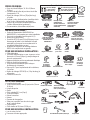
OUTILS NÉCESSAIRES :
• Lunettes de sécurité
• Tourne-écrous de 6,3 mm (1/4 po) et de 7,9 mm
(5/16 po)
• Lampe de poche
• Gants
• Clé à molette (15,2 cm [6 po])
• Tournevis Phillips
• Ruban à mesurer
• Niveau
• Équerre de charpentier
• Seau pour recueillir l’eau lors du rinçage
de la conduite d’eau
• Coupe-tubes
• Clé à douille de 23,8 mm (15/16 po)
POUR UNE NOUVELLE INSTALLATION :
• Jeu de scies-clochet
• Perceuse et forets appropriés
PIÈCES FOURNIES :
• Deux vis à bois Phillips n° 8-18 x 15,8 mm
(5/8 po)
• Couvercle de la boîte de jonction et vis à tête
hexagonale n° 10
• Boyau de vidange (198 cm [78 po] de long)
et collier
• Protège-cordon d’alimentation (modèles dotés
d’un cordon d’alimentation seulement)
• Fils pour la conversion (modèles dotés d’un
cordon d’alimentation seulement)
• Documentation, échantillons et(ou) bons
MATÉRIEL NÉCESSAIRE :
• Cordon d’alimentation WX09X70910 ou
WX09X70911, si nécessaire pour votre installation
• Connecteurs vissables homologués UL (3)
• Ruban pour joints filetés
• Coude de 90° (19,1 mm [3/4 po] filet pour tuyau
d’arrosage de jardin à une extrémité et l’autre
extrémité conçue pour le raccordement à la
conduite d’alimentation en eau)
• Ensemble de supports de montage latéraux
GPF65 si le comptoir est en granite
POUR UNE NOUVELLE INSTALLATION :
• Câble électrique
• Conduite d'alimentation en eau–tuyau en cuivre
d'au moins 9,5 mm (3/8 po) (y compris bague et
écrou à compression)
• Bague anti-traction pour le raccordement électrique
• Robinet d'arrêt (recommandé)
• Coupure anti-refoulement pour le boyau
de vidange, si nécessaire
• Raccord en T pour la plomberie de la résidence,
s'il y a lieu
• Boyau de vidange GPF10S (3 m / 10 pi de long), si
nécessaire
• Colliers à vis sans fin
Collier
Boyau de vidange
de 198 cm (78 po)
Ruban pour
MRLQWV¿OHWpV
3 connecteurs vissables
Conduite d'eau chaude–
tuyau en cuivre d'au
moins 9,5 mm (3/8 po)
Câble électrique ou
cordon d'alimentation
WR09X70910 ou
WX09X70911
Coupure
anti-refoulement
&ROOLHUVjYLVVDQV¿Q
Bague anti-traction
Tournevis
Phillips
Niveau
Équerre de
charpentier
Ruban à mesurer
Lunettes de sécurité
Lampe de poche
Gants
Jeu de
scies-cloche
Perceuse
et forets
Robinet
d'arrêt
Tourne-écrous
de 6,3 mm (1/4 po)
et de 7,9 mm (5/16 po)
Clé à molette
Ensemble
de supports
de montage
latéraux GPF65
Vis à bois Phillips
n° 8 de 15,8 mm
(5/8 po) de long
Ensemble de Vis
Vis à tête hexagonale n° 10
de 12,7 mm (1/2 po) de long
pour boîte de jonction
Couvercle
de la boîte
de jonction
2
Protège-cordon
d'alimentation
(modèles dotés d'un
cordon d’alimentation
seulement)
Fils pour la
conversion (modèles
dotés d’un cordon
d’alimentation
seulement)
Clé à douille de 23,8 mm (15/16 po)
Seau
Boyau de vidange
facultatif GPF10S
de 3 m (10 pi)
Raccord en T
Raccord
pour boyau
de vidange
facultatif
Coude de 90°
Coupe-tubes

3
Préparation pour l'installation – Ouverture dans les armoires
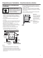
PRÉPARATION DE L'OUVERTURE DANS
LES ARMOIRES
Figure A
• L'ouverture dans les armoires doit mesurer au
moins 61,0 cm (24 po) de largeur et de profondeur,
et 87,6 cm ± 6,3 mm (34 1/2 po ± 1/4 po) de
hauteur à partir du plancher jusqu'au-dessous
GXFRPSWRLU
• Le mur du fond doit être exempt de tuyaux
RXGH¿OV
• Les armoires adjacentes doivent être à l'équerre
HWGDSORPESRXUXQHLQVWDOODWLRQDSSURSULpH
5HSRUWH]YRXVjOD)LJXUH$
• Dans le cas d'une installation dans un coin,
prévoyez un jeu d'au moins 5,1 cm (2 po) entre
OHODYHYDLVVHOOHHWOHPXUDGMDFHQW
• Prévoyez au moins 69 cm (27 po) à l'avant
du lave-vaisselle pour ouvrir la porte
FRPSOqWHPHQW5HSRUWH]YRXVjOD)LJXUH%
• Assurez-vous que le plancher est de niveau
à l'intérieur de l’ouverture et au même niveau
TXHOHSODQFKHU¿QLGHODFXLVLQHD¿QGHIDFLOLWHUOH
retrait du lave-vaisselle si jamais il faut le réparer
GDQVOHIXWXU
Figure B
• Le lave-vaisselle doit être installé au maximum
à 3 mètres (10 pieds) de l’évier pour assurer une
YLGDQJHDGpTXDWH
• Le dessus, les côtés et l’arrière du lave-vaisselle
doivent être complètement dissimulés à l’intérieur
GHO·RXYHUWXUH
• Le lave-vaisselle ne doit soutenir aucune partie
GHODVWUXFWXUHGHVDUPRLUHV
2" Minimum
Countertop
Dishwasher
27" Minimum
Dégagements :
Dans le cas d’une installation
dans un coin, veuillez prévoir
un dégagement d’au moins
5,1 cm (2 po) entre le lave-
vaisselle et les armoires,
le mur ou un électroménager
DGMDFHQW
Veuillez prévoir un
dégagement d’au moins
69 cm (27 po) à l’avant
GXODYHYDLVVHOOH
Pour réduire les risques de choc
électrique, d'incendie ou de blessures,
l'installateur doit s'assurer que le lave-
vaisselle est complètement encastré
au moment de l'installation.
87,6 cm ± 6,3 mm
(34 1/2 po ± 1/4 po)
du dessous
du comptoir
au plancher
Le mur du fond
doit être exempt
GHWX\DX[RXGH¿OV
12,5 cm
(5 po)
12,5 cm
(5 po)
10,1 cm
(4 po)
61,0 cm
(24 po)
PLQ
Armoires
à l'équerre
et d'aplomb
15,2 cm
(6 po)
10,1 cm
(4 po)
Le plancher DOIT
être au même niveau
que le plancher
de la pièce
La partie ombrée est réservée
à la plomberie et à l'électricité
Comptoir
Lave-vaisselle
69 cm (27 po)
minimum
5,1 cm (2 po) minimum
ADVERTISSEMENT

32"
Min.
18"
Min.
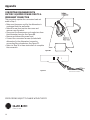
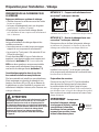
MÉTHODE N° 1 – Coupure anti-refoulement avec
raccord en T ou broyeur à déchets
Installation avec broyeur à déchets
MÉTHODE N° 2 – Boucle de vidange élevée avec
raccord en T ou broyeur à déchets
Prévoyez une façon de fixer le boyau de vidange
DXGHVVRXVGXFRPSWRLU/DIL[DWLRQGXER\DXGH
YLGDQJHVHUDHIIHFWXpHjXQHpWDSHXOWpULHXUH
Installation avec raccord en T
Figure C
Installation avec raccord en T
Installation avec broyeur à déchets
Figure D
Installez le raccord en T ou le broyeur à déchets
et la coupure anti-refoulement en conformité avec
OHVGLUHFWLYHVGXIDEULFDQW
Préparation des armoires
Percez un trou de 3,8 cm (1 1/2 po) de diamètre
dans la paroi de l’armoire qui se trouve dans
la partie ombrée de la Figure A pour le boyau
GHYLGDQJH$VVXUH]YRXVTXHO·RULILFHQHSUpVHQWH
SDVG·DUrWHVYLYHV/HER\DXGHYLGDQJHVHUDLQVpUp
dans ce trou et raccordé au renvoi au cours d’une
pWDSHXOWpULHXUH
IMPORTANT – Lorsque vous
branchez le boyau de vidange
à un broyeur à déchets, assurez-
vous d’enlever le bouchon
de vidange. Le lave-vaisselle
ne pourra pas se vider si vous
laissez le bouchon en place.
32"
Min.
18"
Min.
Préparation pour l’installation – Vidange
Remove
Drain
Plug
PRÉPARATION DE LA PLOMBERIE POUR
LA VIDANGE
Exigences relatives au système de vidange
• Veuillez observer les ordonnances et les codes
ORFDX[HQYLJXHXU
• Le boyau de vidange doit avoir une longueur
PD[LPDOHGHPqWUHVSLHGV
• Il faut prévoir une boucle de vidange élevée
RXO·LQVWDOODWLRQG·XQHFRXSXUHDQWLUHIRXOHPHQW
9RLUFLGHVVRXV
Méthode de vidange
Le type d’installation de vidange dépend des
conditions suivantes :
• Les ordonnances ou codes locaux en vigueur
exigent-ils une coupure anti-refoulement?
• Le raccord en T se trouve-t-il à moins de 46 cm
(18 po) du plancher?
Si vous répondez OUI à l’une ou l’autre de ces
questions, vous devez installer une coupure anti-
refoulement (méthode n° 1)6LYRXVUpSRQGH]
NON aux deux questions, vous pouvez installer
une coupure anti-refoulement ou aménager
une boucle de vidange élevée (méthode n° 2)
Considérations spéciales dans le cas d’un
lave-vaisselle installé sur une plateforme
Si le lave-vaisselle est installé sur une plateforme,
il faut aménager une boucle de vidange à une
hauteur d’au moins 82 cm (32 po) au-dessus de
la plateforme, en plus d’installer la coupure anti-
refoulement indiquée ci-dessus, afin d’assurer une
YLGDQJHDGpTXDWH
ATTENTION
Il FAUT installer une coupure anti-refoulement si le boyau
de vidange est relié à un raccord en T ou à un broyeur
à déchets situé à moins de 46 cm (18 po) du plancher.
Si le boyau de vidange avec la coupure anti-refoulement
ne se trouve pas à une hauteur minimale de 82 cm (32 po)
au-dessus du plancher, la boucle de vidange élevée
ne pourra pas assurer une vidange appropriée du
lave-vaisselle, ce qui pourrait causer des dommages
à l'appareil.
46 cm
(18 po)
PLQ
46 cm
(18 po)
PLQ
81 cm
(32 po)
PLQ
81 cm
(32 po)
PLQ
Enlevez le
bouchon
de vidange
4
La page charge ...
La page charge ...
La page charge ...
La page charge ...
La page charge ...
La page charge ...
La page charge ...
La page charge ...
La page charge ...
La page charge ...
La page charge ...
La page charge ...
-
 1
1
-
 2
2
-
 3
3
-
 4
4
-
 5
5
-
 6
6
-
 7
7
-
 8
8
-
 9
9
-
 10
10
-
 11
11
-
 12
12
-
 13
13
-
 14
14
-
 15
15
-
 16
16
-
 17
17
-
 18
18
-
 19
19
-
 20
20
-
 21
21
-
 22
22
-
 23
23
-
 24
24
-
 25
25
-
 26
26
-
 27
27
-
 28
28
-
 29
29
-
 30
30
-
 31
31
-
 32
32


GE GSD2100VBB Manuel utilisateur
- Catégorie
- Lave-vaisselle
- Taper
- Manuel utilisateur
dans d''autres langues
- English: GE GSD2100VBB User manual
