GE Profile GEJV936DSS Le manuel du propriétaire
- Catégorie
- Hottes
- Taper
- Le manuel du propriétaire

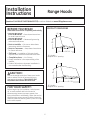
Range Hoods
Vented
LI275B 49-80520-5 01-13 GE
Safety Instructions ........... 2
Operating Instructions
Fan Control ......................3
Light Control .....................4
Care and Cleaning
Grease Filters ....................5
Hood Lights ......................6
Stainless Steel Surfaces ..........5
Installation Instructions . .6–17
Troubleshooting Tips .......18
Consumer Support
Consumer Support .............. 22
Owner Registration ...........19, 20
Warranty ....................... 21
Write the model and serial
numbers here:
Model # _______________
Serial # ________________
You can find them on a label
on the inside of the hood.
JV936
JV966
CV936
CV966
Owner’s Manual
and Installation
Instructions
GEAppliances.com

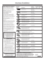
IMPORTANT SAFETY INFORMATION.
READ ALL INSTRUCTIONS BEFORE USING.
2
SAFETY PRECAUTIONS
WARNING – TO REDUCE THE RISK OF FIRE,
ELECTRIC SHOCK OR INJURY TO PERSONS, OBSERVE THE
FOLLOWING:
A. Use this unit only in the manner intended by the manufacturer.
If you have questions, contact the manufacturer.
B. Before servicing or cleaning unit, switch power off at service
panel and lock the service disconnecting means to prevent
power from being switched on accidentally. When the service
disconnecting means cannot be locked, securely fasten a
prominent warning device, such as a tag, to the service panel.
C. Do not use this unit with any solid-state speed control device.
D. This unit must be grounded.
CAUTION – FOR GENERAL VENTILATING USE ONLY.
DO NOT USE TO EXHAUST HAZARDOUS OR EXPLOSIVE MATERIALS
AND VAPORS.
WARNING – TO REDUCE THE RISK OF INJURY TO
PERSONS IN THE EVENT OF A RANGE TOP GREASE FIRE, OBSERVE
THE FOLLOWING*:
A. SMOTHER FLAMES with a close-fitting lid, cookie sheet or metal
tray, then turn off the burner. BE CAREFUL TO PREVENT BURNS. If
the flames do not go out immediately, EVACUATE AND CALL THE
FIRE DEPARTMENT.
B. 1(9(53,&.83$)/$0,1*3$1³<RXPD\EHEXUQHG
C. '212786(:$7(5LQFOXGLQJZHWGLVKFORWKVRUWRZHOV³D
violent steam explosion will result.
D. Use an extinguisher ONLY if:
1. You know you have a Class ABC extinguisher, and you
already know how to operate it.
2. The fire is small and contained in the area where it started.
3. The fire department is being called.
4. You can fight the fire with your back to an exit.
* Based on “Kitchen Fire Safety” published by NFPA.
WARNING – TO REDUCE THE RISK OF A RANGE
TOP GREASE FIRE:
A. Never leave surface units unattended at high settings. Boilovers
cause smoking and greasy spillovers that may ignite. Heat oils
slowly on low or medium settings.
B. Always turn hood ON when cooking on high heat or when
flambéing food (i.e. Crepes Suzette, Cherries Jubilee, Peppercorn
Beef Flambé).
C. Clean ventilating fans frequently. Grease should not be allowed
to accumulate on fan or filter.
D. Use proper pan size. Always use cookware appropriate for the
size of the surface element.
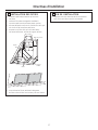
WARNING – TO REDUCE THE RISK OF FIRE,
ELECTRIC SHOCK OR INJURY TO PERSONS, OBSERVE THE
FOLLOWING:
A. Installation work and electrical wiring must be done by qualified
person(s) in accordance with all applicable codes and standards,
including fire-rated construction.
B. Sufficient air is needed for proper combustion and exhausting
of gases through the flue (chimney) of fuel burning equipment
to prevent back drafting. Follow the heating equipment
manufacturer’s guideline and safety standards such as
those published by the National Fire Protection Association
(NFPA), the American Society for Heating, Refrigeration and Air
Conditioning Engineers (ASHRAE) and the local code authorities.
When applicable, install any makeup (replacement) air system
in accordance with local building code requirements. Visit
GEAppliances.com for available makeup air solutions.
C. When cutting or drilling into wall or ceiling, do not damage
electrical wiring and other hidden utilities.
D. Ducted fans must always be vented to the outdoors.
WARNING – TO REDUCE THE RISK OF FIRE AND TO
3523(5/<(;+$867$,5%(685(72'8&7$,52876,'(³'2127
VENT EXHAUST AIR INTO SPACES WITHIN WALLS OR CEILINGS OR
INTO ATTICS, CRAWL SPACES OR GARAGES.
WARNING – TO REDUCE THE RISK OF FIRE, USE
ONLY METAL DUCTWORK.
Do not attempt to repair or replace any part of your hood unless
it is specifically recommended in this guide. All other servicing
should be referred to a qualified technician.
READ AND FOLLOW THIS SAFETY INFORMATION CAREFULLY.
READ AND SAVE THESE INSTRUCTIONS

Using the hood controls. GEAppliances.com
Throughout this manual, features and appearance may vary from your model.
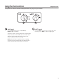
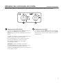
FAN Control
Turn the FAN speed control to LO, MED LO,
MED HI or HI, as needed.
Continuous use of the fan system while cooking helps
keep the kitchen comfortable and less humid. It also
reduces cooking odors and soiling moisture that
create a frequent need for cleaning.
NOTE: When the fan is operating on the LO setting,
it will be very quiet. Always make sure that the fan is
turned OFF when you are finished in the kitchen.
LIGHT Control
Turn the LIGHT control to HI for bright light while
cooking. Turn to NITE for use as a night light.
3

Care and cleaning of the vent hood.
Be sure electrical power is off and all surfaces are cool before cleaning or servicing any part of the vent hood.
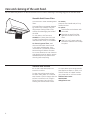
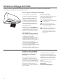
The hood has 2 metal reusable grease
filters.
The metal filters trap grease released
by foods on the cooktop. They also
help prevent flaming foods on the
cooktop from damaging the inside of
the hood.
For this reason, the filters must
ALWAYS be in place when the hood
is used. The grease filters should be
cleaned once a month, or as needed.
To clean the grease filters, soak
them and then swish them around
in hot water and detergent. Don’t
use ammonia or ammonia products
because they will darken the metal.
Do not use abrasives or oven cleaners.
Light brushing can be used to remove
embedded dirt. Rinse, shake and let
them dry before replacing.
To remove:
Grasp the filter handle and pull it up,
forward and out.
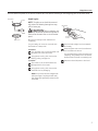
To replace:
Hold the filter at the bottom with
the handle.
Place the top end of the filter
against the inside front of the
hood.
Slide it up until it stops and push
the bottom end back until it snaps
into place.
Reusable Metal Grease Filters
Do not use a steel wool pad; it will
scratch the surface.
To clean the stainless steel surface,
use warm sudsy water or a stainless
steel cleaner or polish. Always wipe the
surface in the direction of the grain.
Follow the cleaner instructions for
cleaning the stainless steel surface.
To inquire about purchasing stainless
steel appliance cleaner or polish, or to
find the location of a dealer nearest
you, please call our toll-free number:
National Parts Center
800.626.2002
GEAppliances.com
Stainless Steel Surfaces
4

5
GEAppliances.com
Be sure electrical power is off and all surfaces are cool before cleaning or servicing any part of the vent hood.
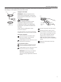
Hood Lights
NOTE: The glass cover should be removed
only when cold. Wearing latex gloves may
offer a better grip.
CAUTION: Before replacing your
light bulb, disconnect the electrical power to
the hood at the main fuse or circuit breaker
panel.
Be sure to let the light cover and bulb cool
completely.
For your safety, do not touch a hot bulb with
bare hands or a damp cloth.
To remove:
Turn the glass cover counterclockwise until
the glass cover clears the socket.
Using gloves or a dry cloth, remove the
bulb by pulling it straight out.
To replace:
Use a new 12-volt, 20-watt (maximum)
Halogen bulb for a G-4 base.
Using gloves or a dry cloth, remove the
new bulb from its packaging.
NOTE: Do not touch the new halogen bulb
with bare fingers. Touching the bulb with
bare fingers will significantly reduce the life
of the bulb.
Push the bulb straight into the receptacle
all the way.
Place the glass cover onto the socket and
turn clockwise until secure.
For improved lighting, clean the glass cover
frequently using a damp cloth. This should
be done when the hood is completely cool.
Reconnect electrical power to the hood.
Bulb
Socket
Glass cover
Receptacle
Use gloves
or cloth
Receptacle

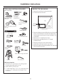
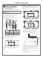
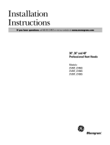
PRODUCT DIMENSIONS
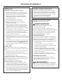
BEFORE YOU BEGIN
Read these Instrucitons completely and carfully.
•
IMPORTANT³ Save these instructions
for local inspector’s use.
•
IMPORTANT³Observe all governing
codes and ordinances.
• Note to Installer ³Be sure to leave these
instructions with the Consumer.
• Note to Consumer ³Keep these instrucitons
for future reference.
• Skill Level³ Installation of this vent hood
requires basic mechanical and electrical skills.
• Completion time ³ 1 to 3 hours.
• Proper installation is the responsibility of the
installer.
• Product failure due to improper installation is
not covered under the Warranty.
Installation
Range Hoods
Instructions
CAUTION :
Due to the weight and size of these vent hoods
and to reduce the risk of personal injury or
damage to the product, TWO PEOPLE ARE
REQUIRED FOR PROPER INSTALLATION.
FOR YOUR SAFETY :
Before beginning the installation, switch power
off at service panel and lock the service
disconnecting means to prevent power from
being switched on accidentally. When the service
disconnecting means cannot be locked, securely
fasten a prominent warning device, such as a tag
to the service panel.
Questions? Call 800.GE.CARES (800.432.2737) or visit our Website at: www.GEAppliances.com.
6
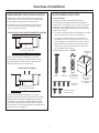
12”
18”
21”
29-7/8”
30” Models
Requires a 30” opening.
36” Models
Requires a 36” opening.
12”
18”
21”
35-7/8”

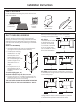
INSTALLATION CLEARANCES
These vent hoods are designed to be installed onto
a wall. They may be installed beneath a soffit or
cabinet.
• Install these hoods 24” Min. to 36” Max. above the
cooking space.
In this installation, the ductwork running from the
top of the hood will be concealed in the soffit or
upper cabinetry.
For this isntallation, a decorative duct cover is
available to conceal the ductwork running from
the top of the hood. Use of the duct cover requires
special consideration to the installation height above
the countertop. See page 12 for details.
OPTIONAL ACCESSORIES
Duct Cover
A decorative duct cover is available to
accommodate 8 to 10 ft. ceiling heights. The duct
cover will expand from 12” Min. or 24” to 36” Max.
height.
• The duct cover conceals the ductwork running
from the top of the hood to the ceiling.
• The duct cover accessory fits both 30” and 36”
wide models. Order the duct cover accessory at
the same time as the vent hood. All accessories
should be on site at the time of hood
installation.
Order JXCHSS
7
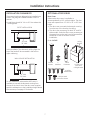
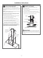
SOFFIT INSTALLATION
24” MIN.
36” MAX.
SOFFIT
WALL MOUNT INSTALLATION
24” MIN.
36” MAX.
2 Wood
Screws
2
Washers
2 Wall
Fasteners 2-Piece Duct
Cover with
Ceiling Bracket
4 Phillips
Head Screws
2 Phillips Head
Decorative Scews
Installation Instructions
Ceiling
Bracket

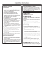
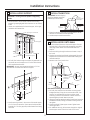
ADVANCE PLANNING
Ductwork Planning
• This hood may be vented vertically through upper cabinets,
soffit or ceiling. A duct transition piece is supplied for vertical
exhaust. Use locally supplied elbows to vent horizontally
through the rear wall. See page 13.
• Determine the exact location of the vent hood.
• Plan the route for venting exhaust to the outdoors.
• Use the shortest and straightest duct route possible. FFor
satisfactory performance, duct run should not exceed 100
equivalent length for any duct configurations.
• Use metal ductwork only.
• A transition piece for 7” round duct is supplied. Use 7” round
duct or you may use 3-1/4” x 12” rectangular.
• Install a wall cap or roof cap with damper at the exterior
opening. Order the wall or roof cap and any transition
needed in advance.
• When applicable, install any makeup (replacement) air
system in accordance with local building code requirements.
Visit GEAppliances.com for available makeup air solutions.
Kit - JXDW1
Order kit JXDW1 if your installation requires horizontal ducting
from the top of the hood through the back wall and:
• You have an 8 ft. ceiling and need to use a JXCH Series
Chimney Cover, or
• You have a 12” cabinet or 12” soffit that the hood is to be
mounted beneath.
This kit provides a duct transition from 7” round to 3-1/4” x 10”
rectangular for through-the-wall venting.
Wall Framing for Adequate Support
• This vent hood is heavy. Adequate structureal support must
be provided. The hood must be secured to vertical studs in
the wall. See page 14.
• We strongly recommend that the vent hood with duct cover
be on site before final framing and wall finishing. This will
also help to accurately locate the ductwork and electrical
service.
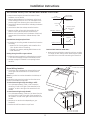
POWER SUPPLY
IMPORTANT - (Please read carefully)
WARNING:
FOR PERSONAL SAFETY, THIS APPLIANCE MUST BE PROPERLY
GROUNDED.
Remove house fuse or open circuit breaker before beginning
installation.
Do not use an extension cord or adapter plug with this
appliance. Follow National electrical codes or prevailing local
codes and ordinances.
Electrical supply
This vent hood must be supplied with 120V, 60 Hz, and
connected to an individual, properly grounded branch circuit,
and protected by a 15 or 20 amp circuit breaker or time delay
fuse.
• Wiring must be 2 wire with ground.
• If the electrical supply does not meet the above
requirements, call a licensed electrician before proceeding.
• Route house wiring as close to the installaton location as
possible in the ceiling, soffit or wall. See page 13 for details.
• Connect the wiring to the house wiring in accordance with
local codes.
Grounding instructions
The grounding conductor must be connected to a ground
metal, permanent wiring system, or an equipment-grounding
terminal or lead on the hood.
WARNING: The improper connection of the
equipment-grounding conductor can result in a risk of electric shock.
Check with a qualified electrician or service representative if you are
in doubt whether the appliance is properly grounded..
DECORATIVE DUCT COVERS
A decorative duct cover is available to fit both model widths.
The duct cover conceals the ductwork running from the top of
the hood to the ceiling or soffit. The duct cover will fit 8 ft. to 10
ft. ceiling heights. See page 12 for details.
Installation Instructions

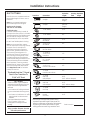
DUCT FITTINGS
Use this chart to compute maximum
permissible lengths for duct runs to
outdoors.
Note: Do not exceed maximum
permissible equivalent lengths!
Maximum duct length:
100 foot for vent hoods.
Flexible ducting:
If flexible metal ducting is used, all
the equivalent feet values in the table
should be doubled. The flexible metal
duct should be straight and smoot
and extended as much as possible.
Do NOT use flexible plastic ducting.
Note
: Any home ventilation system,
such as a ventilation hood, may interrupt
the proper flow of combustion air
and exhaust required by fireplaces,
gas furnaces, gas water heaters and
other naturally vented systems. To
minimize the chance of interruption of
such naturally vented systems, follow
the heating equipment manufaturer’s
guidelines and safety standards such as
those published by NFPA and ASHRAE.
When applicable, install any makeup
(replacement) air system in accordance
with local building code requirements.
Visit GEAppliances.com for available
makeup air solutions.
Total
Equivalent Quantity Equivalent
Duct Piece Dimensions Length* Used Length
7” Round 1 ft.
straight (per foot
length)
3-1/4” x 12” 1 ft.
straight (per foot
length)
7” 90° elbow 14 ft.
7” 45° elbow 9 ft.
3-1/4” x 12” 15 ft.
90° elbow
3-1/4” x 12” 9 ft.
45° elbow
3-1.4” x 12” 36 ft.
90° flat elbow
7” round to
3-1/4” x 12” 1 ft.
transition
3-1/4” x 12”
to 7” round 1 ft.
transition
7” round to
3-1/4” x 12” 4 ft.
transition 90° elbow
3-1/4” x 12” to
7” round 4 ft.
transition 90° elbow
7” round
wall cap 28 ft.
with damper (21 ft. without damper)
3-1/4” x 12”
wall cap 26 ft.
with damper (19 ft. without damp
7” round 39 ft.
roof cap
Round 24 ft.
roof vent
Total Duct Run
* Actual length of straight duct plus duct fitting
equivalent. Equivalent length of duct pieces are
based on actual tests conducted by GE Evaluatioin
Engineering and reflect requirements for good
venting performance with any ventilation hood.
9
Installation Instructions
This Hood Must Use 7” Round
Duct. It Can Transition To
3-1/4” x 12” Duct.
Using a smaller diameter duct size
will reduce performance.
Kit - JXDW1
Order kit JXDW1 if your installation
requires horizontal ducting from the
top of the hood through the back
wall and:
• You have an 8 ft. ceiling and need
to use a JXCH Series Chimney Cover,
or
• You have a 12” cabinet or 12” soffit
that the hood is to be mounted
beneath.
This kit provides a duct transition
from 7” round to 3-1/4” x 10”
rectangular for through-the-wall
venting.

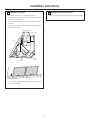
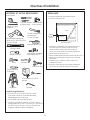
REMOVE THE PACKAGING
• Remove the small box housing the motor.
• Lift the hood out of the box.
• Remove shipping screws holding the wood mounting
piece to the back side of the hood. Set aside wood
mounting piece and screws for later installation. Do
not discard.
• Remove the “V” shaped carton insert.
• Remove parts package from the “V” shaped
cardboard insert.
• Remove junction box cover and knockout.
• Install strain relief onto back or top of hood.
• Remove all tape and packing material from the hood,
duct transition and motor.
TOOLS AND MATERIALS REQUIRED
(NOT SUPPLIED)
Pliers
Wire Cutter/
Stripper
Tin Snips
Allen Wrench
Spirit level
Duct tape
Safety glasses
Ladder
Saber saw or Key Hole Saw
Phillips and
Flat blade
screwdirvers
Additional Materials:
• 120V 60Hz, 15 or 20 Amp, 2 wire with ground.
Properly grounded branch circuit.
• Strain relief for junction box.
•
7” round metal duct, 3-1/4” x 10” rectangular duct
or 3-1/4” x 12” rectangular duct length to suit
installatoin.
1/4” pivoting hex
socket
Hammer
Electric drill with 1/8” and
3/8” bits
Flashlight
UL Listed Wire nuts
Pencil and tape
measure
10
Wood
Mounting
Support
Hood
Parts
Package
Shipping Carton
Motor
Installation Instructions

Installation Instructions
11
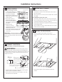
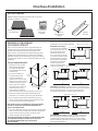
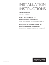
DUCT COVER REQUIREMENTS
We recommend that the vent hood and decorative duct
cover (if used) be on site before final framing and wall
finishing. This will help to accurately locate studs, ductwork,
and electrical service. Read these instructioins to determine
if the duct cover accessory can be used for your installation
situation.
Duct Cover Accessory:
• Use the decoroative duct cover to conceal ductwork
running from the top of the hood to the ceiling.
• The duct cover accessory
consists of 2 pieces. The
outside piece is 12” high,
the inside piece is 22”.
Nested together they are
24” min. expanding to a total
maximum height of 34”.
• The outside piece can be
used alone to fill a 12”
height.
• For heights over 12”, the
ceiling bracket must be
installed to secure the cover
at the top.
To avoid unsightly gaps, plan
the hood installation height for duct cover use.
• The cover will fit a 12” min. height from the top of the
hood to the ceiling or 24” min. and expanding up to 34”
from the top of the hood to the ceiling.
THE DUCT COVER CANNOT BE USED WHEN THE DISTANCE
ABOVE THE TOP OF THE HOOD IS BETWEEN 12” AND 24”.
Review the following examples to ensure a trouble free
installation using the duct cover
accessory.
8ft. Ceilings:
The hood must be installed
at 30” above the cooking
surface (or 66” above the
floor). the duct cover will not
fit if the hood is isntalled at
a lower or higher height.
Use the outside 12” section,
discard the inside section.
9 ft Ceiling: Install the hood 24” min. and up to a maximum
of 30” above the cooking surface. The duct cover will expand
to reach ceiling height.
10 ft. Ceiling: Install the hood 32” min to 36” max. above the
cooking surface. The duct cover will expand to a maximum
of 34” above the top of the hood to meet the ceiling.
PARTS PROVIDED
Locate the hardware accessory box packed with the hood
and check contents.
Screws, wall
fasteners,
washers
Duct Transition
with Damper
2 Aluminum
Grease Filters
Filter
Support
22”
11”
12”
12”
12”
12”
8 ft. Ceiling
30”
24”
9 ft. Ceiling
30”
24”
30”
30”
10 ft. Ceiling
36” Max
32”
34”

12
• Keep the wood support piece and its screws for later
installaton. Do not discard.
• Measure desired distance from the bottom of the hood
to the cooking surface, 24” min. to 36” max. Refer to the
previous page if the accessory duct cover will be used.
• Use a level to draw a horizontal line indicating the bottom
of the hood.
• Use a level to draw the cooktop centerline location.
• Measure 15-3/8” up from the horizontal lline for the
bottom of the hood. Draw another horizontal line.
• Measure 18” up from the line for the bottom of the hood,
draw another horizontal line to indicate the top of the
hood.
FOR VERTICAL (Straight Up) DUCTING:
• If venting out the ceiling, extend the centerline forward on
the ceiling.
- Measure 6-7/8” from drywall to mark centerline for a
7-1/2” dia. duct hole on the ceiling.
- If drywall is not present, add drywall thickness to the
6-7/8” dimension.
Venting through a soffit or upper cabinet:
• Follow the same procedure for ceiling ducting to cut the
7-1/2” dia. hole through the top of the cabinet or soffit.
• See Step 4, page 15 for details to cut opening for duct
transition.
House Wiring Location:
• The junction box is fastenend to the back of the hood
on the right side. See illustrations for hood knockout
locations.
Note:The junction box can be relocated to the inside top of
the hood.
House wiring may enter the junction box from the rear or
the top of the hood at the right side.
To route house wiring through the ceiling or soffit:
– Cut a hole approximately 1” dia., 5-7/8” forward on
the ceiling; 11-1/8” to the right of the centerline for 30”
models or 14-1/8” to the right of the centerline for 36”
models.
To route house wiring through the wall:
– Cut a hole approximately 1” dia. 10-1/16” down from the
top of the hood, 11-1/8” to the right of the centerline for
30” models or 14-1/8” to the right of the centerline for 36”
models..
• Remove top or rear knockout depending on your
installation.
• Install strain relief onto back or top of hood.
FOR DUCTING THROUGH REAR WALL:
• Measure the supplied duct transition with any straight
run length of duct used, plus 90” elbow height. Draw a
horizontal line on the wall intersecting the centerline.
DETERMINE HOOD, DUCTWORK AND WIRING LOCATIONS
5-7/8”
10-1/16”
Knockout
Locations
14-1/8” for 36” Models
11-1/8” for 30” Models
14-1/8” for 36” Models
11-1/8” for 30” Models
Installation Instructions
6-7/8”
Centerline to Wall
FOR CEILING
VENT DUCTING
FOR WALL VENT DUCT
7-1/2” Dia.
Hole
Electrical
Electrical
Top of Hood
Centerline 8” Min.
above Top of
Hood
18”
Wood
Support
15-3/8”
Bottom of Hood

13
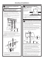
INSTALL HOOD SUPPORT
IMPORTANT : Framing must be capable of supporting
100 lbs.
• Locate at least 2 vertical studs at the wood mounting
location by tapping drywall with a hammer or use a stud
finder.
• Center the supplied wood horizontal support, left to right,
and below the marked line.
• Drill 1/8” pilot holes through the support, drywall and into
the studs. Secure the support to 2 or more vertical studs
with supplied wood screws.
IMPORTANT : Screws must penetrate at least 1-1/2” into
vertical studs. Countersink screws into support.
• Install mounting screws in the center of the wood suppor,
13-1/6” from the centerline. The screws should protrude
forward 1/4”. This 1/4” gap will provide clearance to hang
the hood.
1
7” Min. Opening for Ductwork
Wood Support
Centerline of
Installation Space
15-3/8”
24”
to
36”
13-1/16”
1/4” gap
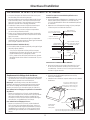
INSTALL TRANSITION
IMPORTANT: Remove shipping
tape from damper and check
that damper moves freely.
• Place the transition piece over the hood exhaust. Secure
transition to hood with 4 screws provided.
• Use duct tape to seal the connection.
2
Duct
Transition
Remove
Shipping Tape
on Damper
Top of
Hood
INSTALL HOOD ONTO WALL
• Lift the hood and place over the wood support. The top
keyhole slots in the hood should engage the protruding
mounting screws. Allow the hood to slide down into
position.
• Pull house wiring through knockout at the rear or top of
the hood.
•
Check to be sure the hood is level and centered. The arrow
shaped cutout in the back of the hood allows viewing the
marked centerline.
• Remove cover from junction box.
Drill Bottom Mounting Hole Locations
• Drill 1/8” pilot holes into the two lower mounting holes.
Enlarge the holes if they do not enter studs to 3/8”. Tap
anchors for wall fasteners into bottom holes. Install
screws by hand into the fasteners to allow anchors to
expand against the wall. Remove screws.
•
Using two large flat washers (supplied), install wood screws or
wall fastener screws, loosely, into lower mounting holes. Do
not tighten.
• Check hood level. Tighten upper screws. Tighten lower
mounting screws..
• For additional security, drive screws through the original
wood support screw holes in the back of the hood.
3
Cutout
Centerline of
Installation
Space
24”
to
36”
Installation Instructions

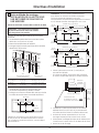
Alternate Mounting Method
INSTALL HOOD TO SOFFIT OR
BENEATH CABINETS
SKIP THIS STEP IF USING WALL MOUNTING METHOD
IMPORTANT : Soffit framing must be capable of
supporting 100 lbs.
When necessary the hood may be installed so that it is
supported by the soffit.
• The soffit should be constructed with 2x4’s.
• Determine the installation location..
• Continue the centerline forward on the bottom of the
cabinet or soffit.
• Mounting screws must be secured to 2 x 4 studs (Dim. “A”)
at locations shown in the above chart.
• Allow minimum opening (Dim. “B”) to accommodate
the duct transition in the soffit
Cut a 10-3/4” x 8-7/16” hole through bottom of soffit or
cabinet for duct transition as shown.
14
IMPORTANT : For additional support and to minimize
vibration during operation, we strongly recommend
that the hood also be secured to the back wall with wall
fastners.
• Drill four 1/8” pilot holes in locations show.
– If mounting to the underside of a cabinet with a
recessed bottom, install shims to fill the gap.
• Drive mounting screws int the studs until they
protrude 1/4”. This 1/4” gap will provide clearance to
engage the keyhole slots in the top of the hood.
• Lift hood onto mounting screws. slide back against
the rear wall.
• Pull house wiring through the knockout at the rear or
top of the hood.
• Tighten mounting screws.
4
Rear Wall
2-3/8”
5-3/8”
5-3/8”
8-7/16”
Top View, Front Side
30” Models
2-9/16”
7-1/16”
2-3/8”
10-3/4”
2-1/4”
14-1/2”
29-7/8”
14-1/2”
12”
8-7/16”
Top View, Front Side
B
A
A
Transition
1/4” Gap
Add
Shimms if
Bottom is
Recessed.
Cabinet
or Soffit
Back
Wall
Engage Keyhole Slots
and Push Back at Wall
Installation Instructions
2-9/16”
7-1/16”
2-3/8”
10-3/4”
2-1/4”
17-1/2”
35-7/8”
17-1/2”
12”
8-7/16”
Vue de dessus, partie avant
36” Models
“A”
Centerline to
Center of Stud
“B”
Opening for
Ductwork
30” Models 14-1/2” 10-3/4” W x 8-7/16 D
36” Nideks 17-1/2” 10-3/4” W x 8-7/16 D

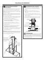
CONNECT DUCTWORK
• Push duct over the end of the transition until it
reaches the stop tabs.
• Install ductwork, making connections in direction of
airflow as illustrated.
• Secure joints in ductwork with sheetmetal screws.
• Wrap all duct joints with duct tape for an airlight seal.
• Use duct tape to seal the flange connection
CAUTION: Do not use sheet metal screws
at the transition to ductwork connection. Doing se will
prevent proper damper operations. Seal connection with
tape only.
Duct Stops
Duct Tape Over
Seam and Screw
Duct Tape Only for Proper
Operation of Damper
Duct Tape Over
Flange
Air Flow
Screw
House
Ductwork
Ductwork
Transition
15
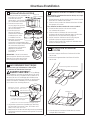
INSTALL CEILING BRACKET
The ceiling bracket must be installed when the duct
cover is used to span 24” or more height above the hood.
The bracket will hold the decorative duct cover in place
at the top.
Note: The ceilling bracket is not required when using only
the 12” section of the duct cover.
• Install the 2 small screws into the sides of the duct
bracket. remove the screws. Pre-tapping the holes will
insue ease of final installation.
• Match center notch on the bracket to the centerline
on the wall and flush against the ceiling.
• Mark the 2 screw hole locations.
• Drill 2/8” pilot holes in marked bracket location.
• If pilot holes do not enterstuds, enlarge the holes to
3/8” and install wall fastener anchors.
• Secure the bracket to the rear wall with wood screws
and washers. Use wall anchors if needed.
Note: Bracket has 2 sets of holes. Use larger holes
for wall fasheners or wood screws with washers. Use
smaller holes for wood screws with washers.
5
Install Ceiling
Bracket When
Duct Cover is
Used to Span 24”
or more
See Step
9 to Install
Duct
Cover.
6
Installation Instructions

16
INSTALL DUCT COVERS
To install the 12” duct cover alone:
• Place the 12” section of the decorative duct cover on
top of the hood.
• Secure the cover on the top of the hood with 4 screws
provided.
To install the 2-piece duct cover:
• Place the 2-piece duct cover on the top of the hood.
• Secure the bottom cover to the top of the hood with 4
screws provided. See illustration, page 16.
• Extend the inside section upwards to meet the ceiling
and ceiling bracket
• Secure the duct cover to the bracket with the 2 small
Phillips screws provided.
INSTALL MOTOR
• Align and engage the slots
in the blower assemly to
the 3 hooks at the rear of
the exhaust opening.
• Rotate motor uplards until it
aligns with the attachment
screw location.
• Secure the motor to
attachment bracket at
the front of the opening
with washer and screw
provided.
• Plug the motor
connector into the
mating hood connector.
Seethe illustration for
the hood connector location. Touch
the hood to locate and make the
connection.
IMPORTANT : Hold the connector so
the two square corner terminals are
at the top as you position the connector
to plug it in.
7
INSTALL FILTER SUPPORT
• Tip filter support into the rear of the hood.
• Insert support tabs into the slots at the rear of the
hood.
• Secure the support to the hood with screws as
shown..
10
9
CONNECT ELECTRICAL
Verify that power is turned off at the source.
WARNING: If house wiring isnot 2-wire
with a ground wire, a ground must be provided by the
installer. When house wiring is aluminum, be sure to use
UL approved anti-oxidant compound and aluminum-to-
copper connectors.
• Use wire nuts to connect incoming ground to green,
white to white, and black to black.
• Push wires into junction box and replace cover. Be
sure wires are not pinched.
8
Installation Instructions
Motor Attachment
Bracket
Motor Hooks
Insert Tabs into Slots
Install 2 Screws
D Use UL Listed Wire Nuts
Ground
A Remove
Junction Box
Cover
B Check that White, Black and
Gree Hood Wires are Threaded
thru Small Hole in Bracket.
C Insert Power
Conduit thru Strain
Relief and Tighten
White
Black

17
FINALIZE INSTALLATION
• Refer to the operating instructions to test all controls.
12
Installation Instructions
INSTALL FILTERS
• Remove protective film covering the filters.
• Insert the filter into the “C” clips mounted to the top of
the vertical front panel.
• Tap the filter against one side to align with outside
opening.
• Pull the filter down into the lower slots at the bottom
of the filter support.
• To remove the filters, grasp the handle, push the filter
up, and pull forward.
11
“C” Clip
Juntion Box
Filter
Support
Filters

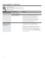
Troubleshooting Tips
Save time and money! Review the chart below first and you
may not need to call for service.
Problem Possible Causes What To Do
Fan does not operate A fuse may be blown or a • Replace fuse or reset circuit breaker.
when the switch is on circuit breaker tripped.
The blower connector is loose • Disconnect power to the unit. Remove the filters
or not plugged into its mating and look up at the blower. If the blower connector
connector. plug is loose or you see the connector dangling,
the installer failed to plug it in securely. Although it
is a blind connection, it is easy to plug in. See the
Installation Instructions in this manual for the plug
location and how to plug the connector in.
Fan fails to circulate air Excessively soiled filters. • Remove the filters, clean if necessary and replace
or moves air slower than them. If cleaning and replacing the filters does not
normal correct the problem, call for service.
• Sufficient makeup (replacement) air is required for
exhausting appliances to operate to rating. Check with
local building codes, which may require or strongly advise
the use of makeup air. Visit GEAppliances.com for available
makeup air solutions.
Before you call for service…
18

19
OWNERSHIP REGISTRATION
P.O. BOX 1780
MISSISSAUGA, ONTARIO
L4Y 4G1
(FOR CANADIAN CONSUMERS ONLY)
Please place in envelope and mail to:
Veuillez mettre dans une enveloppe et envoyez à :

20
La page est en cours de chargement...
La page est en cours de chargement...
La page est en cours de chargement...
La page est en cours de chargement...
La page est en cours de chargement...
La page est en cours de chargement...
La page est en cours de chargement...
La page est en cours de chargement...
La page est en cours de chargement...
La page est en cours de chargement...
La page est en cours de chargement...
La page est en cours de chargement...
La page est en cours de chargement...
La page est en cours de chargement...
La page est en cours de chargement...
La page est en cours de chargement...
La page est en cours de chargement...
La page est en cours de chargement...
La page est en cours de chargement...
La page est en cours de chargement...
La page est en cours de chargement...
La page est en cours de chargement...
La page est en cours de chargement...
La page est en cours de chargement...
-
 1
1
-
 2
2
-
 3
3
-
 4
4
-
 5
5
-
 6
6
-
 7
7
-
 8
8
-
 9
9
-
 10
10
-
 11
11
-
 12
12
-
 13
13
-
 14
14
-
 15
15
-
 16
16
-
 17
17
-
 18
18
-
 19
19
-
 20
20
-
 21
21
-
 22
22
-
 23
23
-
 24
24
-
 25
25
-
 26
26
-
 27
27
-
 28
28
-
 29
29
-
 30
30
-
 31
31
-
 32
32
-
 33
33
-
 34
34
-
 35
35
-
 36
36
-
 37
37
-
 38
38
-
 39
39
-
 40
40
-
 41
41
-
 42
42
-
 43
43
-
 44
44


GE Profile GEJV936DSS Le manuel du propriétaire
- Catégorie
- Hottes
- Taper
- Le manuel du propriétaire
dans d''autres langues
- English: GE Profile GEJV936DSS Owner's manual
Documents connexes
Autres documents
-
GE Appliances JV966 Mode d'emploi
-
Monogram GEZV36RSFSS Guide d'installation
-
 GE Monogram ZVTSFSS Guide d'installation
-
Forno FRHWM5029-30HB Le manuel du propriétaire
-
Forno FRHWM502936HB Le manuel du propriétaire
-
Monogram ZV900SLSS Guide d'installation
-
-
GE ZV755SP1SS Guide d'installation
-
 GE Monogram ZV755SPSS Guide d'installation
-
Caloric CVI28-SS Le manuel du propriétaire

