Dell PowerEdge 2650 Guide de démarrage rapide
- Taper
- Guide de démarrage rapide

www.dell.com | support.dell.com
Dell™ Systems
Microprocessor Upgrade
Installation Guide
9D904ebk5.book Page 1 Wednesday, March 5, 2003 1:42 PM

Notes, Notices, and Cautions
NOTE: A NOTE indicates important information that helps you make better use of your computer.
NOTICE: A NOTICE indicates either potential damage to hardware or loss of data and tells you
how to avoid the problem.
CAUTION: A CAUTION indicates a potential for property damage, personal injury,
or death.
Information in this document is subject to change without notice.
© 2002–2003 Dell Computer Corporation. All rights reserved.
Reproduction in any manner whatsoever without the written permission of Dell Computer Corporation is strictly forbidden.
Trademarks used in this text: Dell and the DELL logo are trademarks of Dell Computer Corporation.
Other trademarks and trade names may be used in this document to refer to either the entities claiming the marks and
names or their products. Dell Computer Corporation disclaims any proprietary interest in trademarks and trade names
other than its own.
March 2003 P/N 9D904 Rev. A05
9D904ebk5.book Page 2 Wednesday, March 5, 2003 1:42 PM

Microprocessor Upgrade Installation Guide 1-1
This document provides instructions about adding or replacing microprocessors. To take
advantage of future options in speed and functionality, you can add secondary
microprocessors or replace microprocessors in your system.
NOTICE: Before you add or replace a microprocessor, check the latest system BIOS
information on the Dell Support website at support.dell.com, and upgrade the BIOS if necessary.
Each microprocessor and its associated cache memory are contained in a pin-grid array
(PGA) package that is installed in a ZIF socket on the system board. The following
subsection describes how to install or replace the microprocessor in either the primary or
secondary microprocessor sockets.
NOTE: In a single microprocessor system, the microprocessor must be installed in the
primary microprocessor socket.
Adding or Replacing a Microprocessor
NOTICE: The secondary microprocessors must be the same speed as the primary
microprocessor.
In addition to the ZIF socket for the primary microprocessor on the system board, other
ZIF sockets might be present to accommodate secondary microprocessors.
The following items are included in the microprocessor upgrade kit:
• A microprocessor
• A heat sink
• Heat-sink retention clip(s)
• A VRM, if applicable
Your upgrade kit may also include a cooling fan.
CAUTION: Before you perform this procedure, read the safety instructions in
your System Information document.
1
Turn off the system, including any peripherals, and disconnect the power cable from
the electrical outlet.
2 Open the system doors, or remove the system cover (see your Installation and
Troubleshooting Guide).
CAUTION: See "Protecting Against Electrostatic Discharge" in the safety
instructions in the System Information document.
3
Remove the cooling shroud, if applicable (see your Installation and Troubleshooting
Guide).
9D904ebk5.book Page 1 Wednesday, March 5, 2003 1:42 PM

1-2 Microprocessor Upgrade Installation Guide
www.dell.com | support.dell.com
4 If you are upgrading an existing microprocessor, remove the microprocessor heat sink.
NOTE: If a cooling fan is mounted on the heat sink, you can remove the heat sink without
removing the fan. However, you can remove the fan to provide easier access to the heat-sink
retention clip(s). For information on removing a cooling fan, see your Installation and
Troubleshooting Guide.
a
Remove the retention clip(s) securing the heat sink to the microprocessor by
pressing down firmly on the retention clip tab, and then removing the clip from
the heat sink.
CAUTION: The microprocessor and heat sink can become extremely hot. Be sure
they have had sufficient time to cool before handling.
NOTICE: Never remove the heat sink from a microprocessor unless you intend to remove the
microprocessor. The heat sink is necessary to maintain proper thermal conditions.
NOTICE: After removing the heat sink, place it upside down on a flat surface to prevent the
thermal interface material from being damaged or contaminated.
b
Remove the heat sink. See your Installation and Troubleshooting Guide for
information on removing the heat sink.
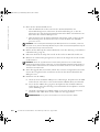
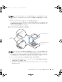
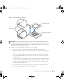
5 Swing the socket release lever upward to the fully open position (see Figure 1-1).
NOTICE: Be careful not to bend any of the pins when removing the microprocessor. Bending
the pins can permanently damage the microprocessor.
6
Lift the microprocessor out of the socket and leave the release lever in the open
position so that the socket is ready for the new microprocessor.
NOTICE: Be careful not to bend any of the pins when unpacking the microprocessor. Bending
the pins can permanently damage the microprocessor.
7
Unpack the new microprocessor.
If any of the pins on the microprocessor appear bent, see "Getting Help" in your
Installation and Troubleshooting Guide.
9D904ebk5.book Page 2 Wednesday, March 5, 2003 1:42 PM

Microprocessor Upgrade Installation Guide 1-3
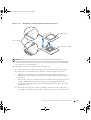
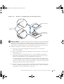
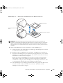
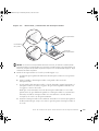
Figure 1-1. Removing and Replacing the Microprocessor
NOTICE: Positioning the microprocessor incorrectly can permanently damage the
microprocessor and the system when you turn on the system. When placing the microprocessor
in the ZIF socket, be sure that all of the pins on the microprocessor go into the corresponding
holes. Be careful not to bend the pins.
8
Install the microprocessor in the socket (see Figure 1-1).
a Ensure that the microprocessor socket release lever is in the fully open position.
b Align pin 1 on the microprocessor with pin 1 on the microprocessor socket.
c With pin 1 of the microprocessor and socket aligned, set the microprocessor
lightly in the socket and ensure that all pins are matched with the correct holes in
the socket.
Because the system uses a ZIF microprocessor socket, there is no need to use force
(which could bend the pins if the microprocessor is misaligned). When the
microprocessor is positioned correctly, it should drop down into the socket with
minimal pressure.
d When the microprocessor is fully seated in the socket, rotate the socket release
lever back down until it snaps into place, locking the microprocessor in the socket.
pin-1 locators
microprocessor
microprocessor socket
9D904ebk5.book Page 3 Wednesday, March 5, 2003 1:42 PM

1-4 Microprocessor Upgrade Installation Guide
www.dell.com | support.dell.com
9 Install the heat sink.
• If the heat sink provided has a protective cover on the underside of the heat sink,
remove and discard the cover to expose the thermal grease or foil thermal interface
material, and then place the heat sink on the microprocessor.
• If heat-sink thermal grease is provided, clean the heat sink and apply the thermal
grease before placing the heat sink on the microprocessor.
NOTICE: To avoid possible damage to the microprocessor, you must align the heat sink so that
the triangular mark on the heat sink points toward the triangular mark on the system board, if
applicable.
10
Orient the heat-sink retention clip as shown in your Installation and Troubleshooting
Guide.
11 Hook the end of the clip without the release tab over the tab on the edge of the socket.
12 Press down on the release tab until the hole on the clip latches onto the ZIF
socket tab.
NOTICE: If a cooling fan is provided with your upgrade kit, you must install the fan on the
microprocessor heat sink to provide proper thermal conditions. For information on installing a
cooling fan, see your Installation and Troubleshooting Guide.
13
If a cooling fan is provided with your upgrade kit or if you removed a cooling fan earlier
in this procedure, install the fan on the microprocessor heat sink.
14 If applicable, install the VRM(s):
a If you are adding a secondary microprocessor, examine the VRM to ensure that it
is the correct VRM for your system.
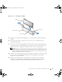
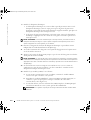
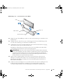
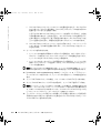
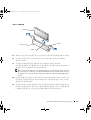
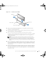
b Insert the VRM in the appropriate secondary VRM connector, ensuring that the
latches at each end of the connector engage (see Figure 1-2).
c If you received two VRMs with the upgrade kit, replace the primary VRM already
installed in the system with one of the VRMs from the upgrade kit.
NOTE: The system does not support mismatched VRMs.
9D904ebk5.book Page 4 Wednesday, March 5, 2003 1:42 PM

Microprocessor Upgrade Installation Guide 1-5
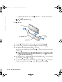
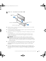
Figure 1-2. Installing a VRM
15
Replace the cooling shroud, if applicable (see your Installation and Troubleshooting
Guide).
16 Close the system doors, or replace the system cover (see your Installation and
Troubleshooting Guide).
17 Reconnect your system and peripherals to their electrical outlets, and turn them on.
As the system boots, it detects the presence of the new processor and automatically
changes the system configuration information in the System Setup program.
NOTE: After you access the inside of the system, the chassis intrusion detector will cause
an alert message to be displayed at the next system startup. This message is stored in the
system’s nonvolatile random-access memory (NVRAM). To clear this message log, see your
systems management software documentation.
18 Enter the System Setup program and ensure that the microprocessor categories match
the new system configuration. For instructions about using the System Setup
program, see your User’s Guide.
19 Run the system diagnostics to verify that the new microprocessor is operating
correctly. See your Installation and Troubleshooting Guide for information about
running the diagnostics and troubleshooting any problems that may occur.
VRM
VRM connector
latches (2)
connector key
9D904ebk5.book Page 5 Wednesday, March 5, 2003 1:42 PM

1-6 Microprocessor Upgrade Installation Guide
www.dell.com | support.dell.com
9D904ebk5.book Page 6 Wednesday, March 5, 2003 1:42 PM

www.dell.com | support.dell.com
Dell
™
系统
微处理器升级安装指南
9D904cbk5.book Page 1 Wednesday, March 5, 2003 10:43 AM

注 注意和警告
注 注表示可以帮助您更好地使用计算机的重要信息
注意
注意表示可能会损坏硬件或导致数据丢失 并告诉您如何避免此类问题
警告
警告表示存在可能导致财产损失 人身伤害或死亡的潜在危险
本文件中的信息如有更改 恕不另行通知
© 2002-2003 Dell Computer Corporation
版权所有 翻印必究
未经
Dell Computer Corporation
书面许可 不准以任何形式进行复制
本文件中使用的商标
Dell
和
DELL
徽标是
Dell Computer Corporation
的商标
本文件中述及的其它商标和产品名称是指拥有相应商标和名称的公司或其制造的产品
Dell Computer
Corporation
对其它公司的商标和产品名称不拥有任何专利权
2003
年
3
月
P/N 9D904 Rev. A05
9D904cbk5.book Page 2 Wednesday, March 5, 2003 10:43 AM

微处理器升级安装指南
2-1
本说明文件提供了有关添加或更换微处理器的说明 您可以在系统中添加次微处理器
或更换微处理器
从而充分利用未来选件的速度和功能
注意 添加或更换微处理器之前 请查看 Dell 支持 Web 站点 support.dell.com 上的最新系
统 BIOS 信息
并在必要时升级 BIOS
每个微处理器及其相应的高速缓存均包含在一个针型栅格阵列
(PGA)
包装内 此包装
安装在主机板上的
ZIF
插槽中
以下小节介绍了如何在微处理器主插槽或次插槽中安
装或更换微处理器
注
在配置单个微处理器的系统中 微处理器必须安装在主插槽中
添加或更换微处理器
注意 次微处理器的速率必须与主微处理器相同
除了主机板上用于主微处理器的
ZIF
插槽外 可能还有其它
ZIF
插槽用于安装次微处
理器
微处理器升级套件包含以下内容
• 一个微处理器
• 一个散热器
• 散热器固定夹
• 一个
VRM
如果可用
升级套件中可能还包含一个冷却风扇
警告
执行此过程之前 请阅读 系统信息 说明文件中的安全说明
1
关闭系统 包括任何外围设备 并从电源插座中断开电源电缆的连接
2
打开系统护盖 或者卸下主机盖 请参阅 安装与故障排除指南
警告
请参阅 系统信息 文件安全说明部分中的 防止静电损害
3
如果可以 请卸下冷却通风罩 请参阅 安装与故障排除指南
4
如果您升级现有的微处理器 请卸下微处理器散热器
注
如果散热器上已安装冷却风扇 您无需卸下风扇即可卸下散热器 但是 卸下风
扇可以使您更方便地拆装散热器固定夹
有关卸下冷却风扇的信息 请参阅 安装与
故障排除指南
a
稳定地按下固定夹卡舌并从散热器上卸下此夹 卸下将散热器固定至微处理器
的固定夹
9D904cbk5.book Page 1 Wednesday, March 5, 2003 10:43 AM

2-2
微处理器升级安装指南
www.dell.com | support.dell.com
警告
微处理器和散热器可能会变得很热 请在处理之前确保它们有足够的时间冷却
注意 除非您准备卸下微处理器 否则请勿卸下微处理器上的散热器 要保持正确散热
散热器必不可少
注意 卸下散热器后 请将其倒置在平坦的表面上 防止损坏或玷污散热材料
b
卸下散热器 有关卸下散热器的信息 请参阅 安装与故障排除指南
5
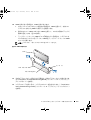
将插槽释放拉杆向上转动至完全打开位置 参见图
2-1
注意 卸下微处理器时 请注意不要弄弯任何插针 弄弯插针将对微处理器造成无法修复
的损坏
6
从插槽中提出微处理器 并使释放拉杆保留在打开位置 以便在插槽中安装新的
微处理器
注意 在打开微处理器的包装时 请注意不要弄弯任何插针 弄弯插针将对微处理器造成
无法修复的损坏
7
打开新微处理器的包装
如果处理器上的任何插针出现弯曲 请参阅 安装与故障排除指南 中的 获得
帮助
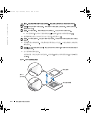
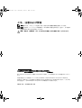
图
2-1
卸下并更换微处理器
插针 1
定位器
微处理器
微处理器插槽
9D904cbk5.book Page 2 Wednesday, March 5, 2003 10:43 AM

微处理器升级安装指南
2-3
注意 如果在微处理器位置不正确的情况下启动系统 会对微处理器和系统造成无法修复
的损坏
在 ZIF 插槽中放置微处理器时 请确保微处理器上的所有插针均已插入相应的插
孔
注意不要弄弯插针
8
将微处理器安装在插槽中 参见图
2-1
a
确保微处理器插槽释放拉杆处于完全打开位置
b
将微处理器上的插针
1
与微处理器插槽上的插针
1
对齐
c
将微处理器与插槽的插针
1
对齐后 请将微处理器轻轻放在插槽中 并确保所
有插针均与插槽中的插孔正确对齐
由于系统使用的是
ZIF
微处理器插槽 因此插入时无需用力 如果微处理器
未对齐
用力过度会弄弯插针 微处理器正确定位后 略微按压即可向下
进入插槽中
d
微处理器在插槽中完全就位后 向下转回插槽释放拉杆直至其卡入到位 将
微处理器锁定在插槽中
9
安装散热器
• 如果附带的散热器下方有一个保护盖
请卸下并丢弃此盖以露出散热膏或散
热材料金属薄片
然后将散热器放置在微处理器上
• 如果附带了散热器散热膏
请先清洁散热器并涂抹散热膏 然后再将散热器
放置在微处理器上
注意 为避免损坏微处理器 对齐散热器时应使其上面的三角形标记指向主机板上的三角
形标记
如果可以
10
按照 安装与故障排除指南 中的说明 确定散热器固定夹的方向
11
挂住固定夹一端 使释放卡舌不会挡在插槽边缘卡舌的上方
12
向下按压释放卡舌 直至固定夹上的小孔锁定在
ZIF
插槽卡舌上
注意 如果升级套件附带了冷却风扇 则必须将风扇安装在微处理器散热器上 从而确保
正确散热
有关安装冷却风扇的信息 请参阅 安装与故障排除指南
13
如果升级套件附带了冷却风扇 或者您在本过程早些时候卸下了冷却风扇 请将
风扇安装在微处理器散热器上
14
如果可以 请安装
VRM
a
如果您添加次微处理器 请检查系统是否使用了正确的
VRM
b
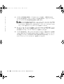
将
VRM
插入适当的次
VRM
连接器 确保连接器每一端的闩锁均已啮合 参
见图
2-2
9D904cbk5.book Page 3 Wednesday, March 5, 2003 10:43 AM

2-4
微处理器升级安装指南
www.dell.com | support.dell.com
c
如果您的升级套件附带了两个
VRM
请使用其中一个来更换已安装在系统中
的主
VRM
注 系统不支持不匹配的 VRM
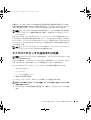
图
2-2
安装
VRM
15
如果可以 请装回冷却通风罩 请参阅 安装与故障排除指南
16
关闭系统护盖 或者装回主机盖 请参阅 安装与故障排除指南
17
将系统和外围设备重新连接至电源插座 然后开机
系统在引导时将会检测是否存在新的处理器 并且自动更改系统设置程序中的系
统配置信息
注 拆装系统内部组件之后 机箱防盗检测器会使系统在下一次启动时显示一则警告
信息
此信息存储在系统的非易失性随机存取存储器 (NVRAM) 中 要清除此信息记
录
请参阅系统管理软件说明文件
18
进入系统设置程序 并确保微处理器类型与新的系统配置相符 有关使用系统设
置程序的说明
请参阅 用户指南
19
运行系统诊断程序 验证新的微处理器是否可以正确运行 有关运行诊断程序以
及排除可能出现的任何故障的信息
请参阅 安装与故障排除指南
VRM
VRM 连接器
闩锁
2 个
连接器栓锁
9D904cbk5.book Page 4 Wednesday, March 5, 2003 10:43 AM

www.dell.com | support.dell.com
Systèmes Dell™
Guide d'installation pour la
mise à niveau du
microprocesseur
9D904fbk5.book Page 1 Wednesday, March 5, 2003 10:26 AM

Remarques, mises en garde et avertissements
REMARQUE : Une REMARQUE indique une information importante destinée à vous aider à
mieux utiliser votre ordinateur.
MISE EN GARDE : Une MISE EN GARDE indique un dommage ou une perte de données
potentiels pouvant survenir et comment éviter ce problème.
ATTENTION : Le message ATTENTION indique une situation potentiellement
dangereuse qui, si elle n'est pas évitée, peut provoquer une détérioration du
matériel ou des blessures pouvant entraîner la mort.
Les informations fournies dans ce document sont susceptibles d'être modifiées sans préavis.
© 2002-2003 Dell Computer Corporation. Tous droits réservés.
La reproduction de ce document de quelque manière que ce soit sans l'autorisation écrite de Dell Computer Corporation
est strictement interdite.
Marques utilisées dans ce document : Dell et le logo DELL sont des marques de Dell Computer Corporation.
Tous les autres noms de marques et marques commerciales utilisés dans ce document se rapportent aux sociétés propriétaires
des marques et des noms de ces produits. Dell Computer Corporation décline tout intérêt dans l'utilisation des marques
déposées et des noms de marques ne lui appartenant pas.
Mars 2003 Réf 9D904 Rév. A05
9D904fbk5.book Page 2 Wednesday, March 5, 2003 10:26 AM

Guide d'installation pour la mise à niveau du microprocesseur 3-1
Ce document contient des instructions concernant l'ajout ou le remplacement de
microprocesseurs. Pour pouvoir tirer parti des futures options offrant une vitesse plus élevée
ou des fonctionnalités supplémentaires, vous pouvez ajouter des microprocesseurs
secondaires ou remplacer ceux qui sont déjà installés dans votre système.
MISE EN GARDE : Avant d'ajouter ou de remplacer un microprocesseur, consultez les
dernières informations relatives au BIOS système sur le site Web d'assistance technique de Dell
à l'adresse support.dell.com et mettez le BIOS à niveau si nécessaire.
Chaque microprocesseur et sa mémoire cache associée sont contenus dans un module PGA
(pin-grid array) qui est installé dans un connecteur ZIF sur la carte système. La sous-section
suivante explique comment installer ou remplacer le microprocesseur sur les connecteurs
pour microprocesseur principal ou secondaire.
REMARQUE : Dans un système à un seul microprocesseur, celui-ci doit être installé
dans le connecteur de microprocesseur principal.
Ajout ou remplacement d'un microprocesseur
MISE EN GARDE : La vitesse des microprocesseurs secondaires doit être identique à celle du
microprocesseur principal.
Outre le connecteur ZIF destiné au microprocesseur principal sur la carte système, il peut
exister d'autres connecteurs ZIF prévus pour accueillir des microprocesseurs secondaires.
Le kit de mise à niveau du microprocesseur contient les éléments suivants :
• Un microprocesseur
• Un dissipateur thermique
• Languette(s) de fixation du dissipateur thermique
• Un module VRM, le cas échéant
Votre kit de mise à niveau peut aussi comporter un ventilateur.
ATTENTION : Avant d'exécuter cette procédure, lisez les instructions de sécurité
du document Informations sur le système.
1
Mettez le système hors tension, y compris les périphériques, puis débranchez le cordon
d'alimentation du secteur.
2 Ouvrez les portes du système ou retirez le capot du système (reportez-vous au Guide
d'installation et de dépannage).
9D904fbk5.book Page 1 Wednesday, March 5, 2003 10:26 AM

3-2 Guide d'installation pour la mise à niveau du microprocesseur
www.dell.com | support.dell.com
ATTENTION : Reportez-vous à la section « Protection contre les décharges
électrostatiques » dans les instructions de sécurité du document Informations
sur le système.
3
Retirez le dissipateur de chaleur, le cas échéant (reportez-vous au Guide d'installation
et de dépannage).
4 Si vous mettez à niveau un microprocesseur déjà installé, retirez son dissipateur
thermique.
REMARQUE : Si un ventilateur est monté sur le dissipateur thermique, vous pouvez le
retirer sans enlever le ventilateur. Toutefois, vous pouvez retirer le ventilateur pour accéder
plus facilement aux languettes de fixation du dissipateur thermique. Pour savoir comment
retirer le ventilateur, reportez-vous au Guide d'installation et de dépannage.
a Retirez la ou les languettes de fixation assujettissant le dissipateur thermique au
microprocesseur en appuyant fermement sur la patte de la languette, puis en
retirant la languette du dissipateur thermique.
ATTENTION : Le microprocesseur et le dissipateur thermique peuvent être
brûlants. Laissez-les se refroidir suffisamment avant de les manipuler.
MISE EN GARDE : Ne retirez jamais le dissipateur thermique d'un microprocesseur si vous
n'avez pas l'intention de retirer le microprocesseur lui-même. Le dissipateur thermique est en
effet indispensable pour maintenir les conditions de température adéquates.
MISE EN GARDE : Après avoir retiré le dissipateur thermique, placez-le à l'envers sur une
surface plane afin d'empêcher toute détérioration ou contamination du matériau de l'interface
thermique.
b
Retirez le dissipateur thermique. Reportez-vous au Guide d'installation et de
dépannage pour savoir comment procéder.
5 Redressez la manette de dégagement du connecteur (voir la Figure 3-1).
MISE EN GARDE : Veillez à ne pas tordre les broches lors du retrait du microprocesseur.
Vous risqueriez sinon d'endommager définitivement le microprocesseur.
6
Sortez le microprocesseur du connecteur tout en laissant la manette relevée afin de
pouvoir installer le nouveau microprocesseur.
MISE EN GARDE : Veillez à ne pas tordre les broches lorsque vous extrayez le
microprocesseur de son emballage. Vous risqueriez sinon d'endommager définitivement le
microprocesseur.
7
Sortez le nouveau microprocesseur de son emballage.
Si certaines des broches du microprocesseur semblent tordues, reportez-vous à
« Obtention d'aide » dans votre Guide d'installation et de dépannage.
9D904fbk5.book Page 2 Wednesday, March 5, 2003 10:26 AM

Guide d'installation pour la mise à niveau du microprocesseur 3-3
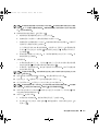
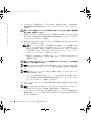
Figure 3-1. Retrait et remplacement du microprocesseur
MISE EN GARDE : Un mauvais positionnement du microprocesseur risquerait d'endommager
définitivement le microprocesseur et le système lorsque vous le remettrez sous tension. Lors de
l'installation du microprocesseur dans le connecteur ZIF, vérifiez que toutes les broches du
microprocesseur s'enfoncent dans les trous correspondants. Veillez à ne pas tordre les broches.
8
Installez le microprocesseur dans le connecteur (voir la Figure 3-1).
a Vérifiez que la manette de dégagement du connecteur est sur la position
d'ouverture maximale.
b Faites correspondre la broche 1 du microprocesseur à la broche 1 du connecteur
du microprocesseur.
c Une fois la broche 1 du microprocesseur et le connecteur alignés, positionnez
doucement le microprocesseur dans le connecteur et assurez-vous que toutes les
broches correspondent bien aux trous appropriés du connecteur.
Le connecteur ZIF vous évite de devoir forcer pour installer le microprocesseur
(ce qui risquerait de tordre les broches si le microprocesseur n'est pas bien aligné).
Une fois le microprocesseur correctement positionné, une pression très légère doit
suffire pour pouvoir l'enfoncer dans le connecteur.
d Lorsque le microprocesseur est installé à fond dans le connecteur, faites pivoter et
abaissez la manette de dégagement du connecteur jusqu'à ce qu'elle s'enclenche,
verrouillant le microprocesseur dans le connecteur.
repères de la
broche 1
microprocesseur
connecteur du
microprocesseur
9D904fbk5.book Page 3 Wednesday, March 5, 2003 10:26 AM

3-4 Guide d'installation pour la mise à niveau du microprocesseur
www.dell.com | support.dell.com
9 Installez le dissipateur thermique.
• Si le dissipateur thermique est recouvert d'un capot de protection situé sous le
dissipateur thermique, retirez le capot pour exposer la graisse de protection
thermique ou la feuille de protection thermique en papier métallisé, puis placez le
dissipateur thermique sur le microprocesseur.
• Si la graisse de protection thermique est fournie à part, nettoyez le dissipateur
thermique et appliquez-lui une couche de cette graisse avant de le placer sur le
microprocesseur.
MISE EN GARDE : Pour éviter d'endommager le microprocesseur, vous devez orienter le
dissipateur thermique de façon à ce que le repère triangulaire du dissipateur pointe vers le
repère triangulaire de la carte système, le cas échéant.
10
Orientez la languette de fixation du dissipateur thermique en procédant comme
indiqué dans le Guide d'installation et de dépannage.
11 Accrochez l'extrémité de la languette sans la patte de dégagement sur la patte située
sur le rebord du connecteur.
12 Appuyez sur la patte de dégagement jusqu'à ce que le trou de la languette s'enclenche
sur la patte du connecteur ZIF.
MISE EN GARDE : Si votre kit de mise à niveau comporte un ventilateur, vous devez installer
le ventilateur sur le dissipateur thermique du microprocesseur afin de maintenir une température
appropriée. Pour savoir comment installer le ventilateur, reportez-vous au Guide d'installation et
de dépannage.
13
Si votre kit de mise à niveau comporte un ventilateur ou si vous avez retiré un
ventilateur au cours de cette procédure, vous devez installer le ventilateur sur le
dissipateur thermique du microprocesseur.
14 Installez le(s) module(s) VRM, le cas échéant :
a Si vous ajoutez un microprocesseur secondaire, examinez le module VRM et
assurez-vous qu'il convient à votre système.
b Introduisez le module VRM dans le connecteur VRM secondaire approprié, en
veillant à ce que les loquets placés à chaque extrémité du connecteur
s'enclenchent (voir la Figure 3-2).
c Si votre kit de mise à niveau contenait deux VRM, remplacez le VRM principal
actuellement installé sur votre système par l'un des VRM du kit.
REMARQUE : Le système ne prend pas en charge l'installation de deux modules VRM
différents.
9D904fbk5.book Page 4 Wednesday, March 5, 2003 10:26 AM
La page est en cours de chargement...
La page est en cours de chargement...
La page est en cours de chargement...
La page est en cours de chargement...
La page est en cours de chargement...
La page est en cours de chargement...
La page est en cours de chargement...
La page est en cours de chargement...
La page est en cours de chargement...
La page est en cours de chargement...
La page est en cours de chargement...
La page est en cours de chargement...
La page est en cours de chargement...
La page est en cours de chargement...
La page est en cours de chargement...
La page est en cours de chargement...
La page est en cours de chargement...
La page est en cours de chargement...
La page est en cours de chargement...
La page est en cours de chargement...
La page est en cours de chargement...
La page est en cours de chargement...
La page est en cours de chargement...
La page est en cours de chargement...
La page est en cours de chargement...
La page est en cours de chargement...
La page est en cours de chargement...
La page est en cours de chargement...
La page est en cours de chargement...
La page est en cours de chargement...
La page est en cours de chargement...
La page est en cours de chargement...
La page est en cours de chargement...
La page est en cours de chargement...
La page est en cours de chargement...
La page est en cours de chargement...
-
 1
1
-
 2
2
-
 3
3
-
 4
4
-
 5
5
-
 6
6
-
 7
7
-
 8
8
-
 9
9
-
 10
10
-
 11
11
-
 12
12
-
 13
13
-
 14
14
-
 15
15
-
 16
16
-
 17
17
-
 18
18
-
 19
19
-
 20
20
-
 21
21
-
 22
22
-
 23
23
-
 24
24
-
 25
25
-
 26
26
-
 27
27
-
 28
28
-
 29
29
-
 30
30
-
 31
31
-
 32
32
-
 33
33
-
 34
34
-
 35
35
-
 36
36
-
 37
37
-
 38
38
-
 39
39
-
 40
40
-
 41
41
-
 42
42
-
 43
43
-
 44
44
-
 45
45
-
 46
46
-
 47
47
-
 48
48
-
 49
49
-
 50
50
-
 51
51
-
 52
52
-
 53
53
-
 54
54
-
 55
55
-
 56
56


