
PLEASE CONTACT US
BEFORE RETURNING
YOUR UNIT TO THE STORE
1-800-523-3987
www.sauder.com
Made in the USA
Archbold, OH
NOTE: THIS INSTRUCTION BOOKLET CONTAINS
IMPORTANT SAFETY INFORMATION.
PLEASE READ AND KEEP FOR FUTURE REFERENCE.
English .................... Page 1-18
Français ...............Pages 19-21
Espanol .............Páginas 22-24
Lot #: 346718 09 / 10 / 12
Date Purchased: ____________________
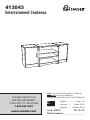
413043
Entertainment Credenza

ASSEMBLY TOOLS REQUIRED
Hammer
Tip Shown Actual Size
No. 2 Phillips Screwdriver
TABLE OF CONTENTS
Part Identifi cation .......................3
Hardware Identifi cation .............4
Assembly Steps ....................5-18
Français ..............................19-21
Espanol ...............................22-24
Safety .................................25-26
Warranty ...................................27
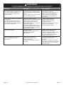
Use of a TV that is too heavy or large is hazardous. A TV that is too heavy will create a risk of a tip-over that can cause severe injury
or death. A TV that is too large for the available space might be accidentally pushed or bumped off the furniture, or subject to tip-over.
• Check the size and weight of your TV. Compare it to the diagram below – before you begin assembly!
• This Sauder unit is designed for use with televisions weighing less than 135 pounds. Never use with a TV that weighs more.
• The size of the television, front-to-back and side-to-side, must fi t within the space defi ned in the diagram.
• Never place the front edge of the TV past the front edge of the TV support shelf (or stop molding – if equipped)
• Never allow the sides of the TV to extend past the side edges of the TV support surface.
• If the TV has a CRT picture tube, the picture tube cone may extend past the rear of the support shelf.
• Be sure to apply the warning label as instructed in the last assembly step. The label provides important safety related information.
WARNING
17-1/8" 27-1/2"
135 lbs.
Page 2 www.sauder.com/services 413043

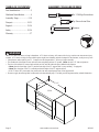
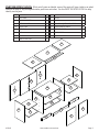
PART IDENTIFICATION: While not all parts are labeled, some of the parts will have a label or an inked
letter on the edge to help distinguish similar parts from each other. Use this PART IDENTIFICATION to help
identify similar parts.
A RIGHT END 1
B LEFT END 1
C RIGHT UPRIGHT 1
D LEFT UPRIGHT 1
E RIGHT TOP 1
F LEFT TOP 1
G TOP 1
H BOTTOM 1
I SMALL BOTTOM 2
J SMALL BACK 2
K BACK 1
L DOOR 2
M LARGE ADJUSTABLE SHELF 2
N ADJUSTABLE SHELF 2
O CENTER SKIRT 1
P SIDE SKIRT 2
Q STOP MOLDING 1
Page 3
www.sauder.com/services413043
A
B
C
D
E
F
G
H
I
J
K
L
M
N
O
P
Q
J
N
I
M
P
L

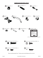
HARDWARE IDENTIFICATION
Screws are shown actual size. You may receive extra hardware with your unit.
Page 4 www.sauder.com/services 413043
WARNING
Never use this furniture with a TV that is too
large or too heavy. Severe injury or death
can occur. The TV and furniture will be
unstable and may tip.
-The TV must less than 135 lbs.
-The base of the TV must be able to sit
completely on this shelf.
-Refer to instruction book for complete safety
information.
Note: This is a permanent label. Do not try
to remove. Surface will be damaged.
02/ 02 2 6 9 2 3 2 269232
WARNING LABEL - 1
BB
(Refer to the last step for proper location and application)
BLACK 9/16" LARGE HEAD SCREW - 30
DD
ANGLE BRACKET - 15
W
HIDDEN CAM - 23
R2
CAM COVER - 4
Y
RUBBER SLEEVE - 16
AA
METAL PIN - 16
Z
CAM SCREW - 3
T2
CAM DOWEL - 20
S2
BLACK 1/2" FLAT HEAD SCREW - 8
EE
U
HINGE - 4
DOOR STOP - 2
X
NAIL - 52
FF
PULL - 2
V
SILVER 7/8" MACHINE SCREW - 4
CC

Look for this icon. It means a video
assembly tip is available at:
www.sauder.com/services/tips
1
1
S
t
e
p
Page 5
www.sauder.com/services413043
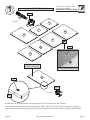
Assemble your unit on a carpeted fl oor or on the empty carton to avoid scratching your unit or the fl oor.
Push twenty-three HIDDEN CAMS (R2) into the ENDS (A and B), UPRIGHTS (C and D), BOTTOMS (H and I), and TOP (G).
Then, insert the metal end of twenty CAM DOWELS (S2) into the HIDDEN CAMS in the ENDS, UPRIGHTS, and BOTTOMS.
Do not tighten the HIDDEN CAMS in this step.
Arrow
Hole
A
B
C
D
G
H
I
I
Do not insert CAM
DOWELS into this part.
(23 used)
(20 used)
Insert the metal end of the CAM
DOWEL into the HIDDEN CAM.
Arrow
Arrow
R2
S2
Arrow
R2

Page 6 www.sauder.com/services 413043
2
2
S
t
e
p
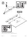
Turn three CAM SCREWS (T2) into the STOP MOLDING (Q).
Fasten the STOP MOLDING (Q) to the TOP (G). Tighten three HIDDEN CAMS.
T2
G
Q
Q
Surface with
HIDDEN CAMS
These surfaces should
be almost even.

Page 7
www.sauder.com/services413043
3
3
S
t
e
p
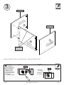
Fasten the UPRIGHTS (C and D) to the BOTTOM (H). Tighten four HIDDEN CAMS.
C
D
H
Surface with
HIDDEN CAMS
Surface without
HIDDEN CAMS
Surface with
HIDDEN CAMS
Finished edge
Finished edge
These holes
must be here.
Caution
Risk of damage or
injury. Hidden Cams
must be completely
tightened. Hidden
Cams that are not
completely tightened
may loosen, and parts
may separate.
To completely tighten:
Start Tighten
Arrow
Maximum
210 degrees
Minimum
190 degrees
Arrow

Page 8 www.sauder.com/services 413043
4
4
S
t
e
p
C
D
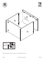
Fasten the UPRIGHTS (C and D) to the TOP (G). Tighten four HIDDEN CAMS.
Q
G
Surface with
HIDDEN CAMS
Maximum
210 degrees
Minimum
190 degrees
Arrow

Page 9
www.sauder.com/services413043
5
5
S
t
e
p
Fasten the SMALL BOTTOMS (I) to the UPRIGHTS (C and D). Tighten four HIDDEN CAMS.
C
D
I
I
Surface with
HIDDEN CAMS
Surface with
HIDDEN CAMS
This hole
must be here.
This hole
must be here.
Maximum
210 degrees
Minimum
190 degrees
Arrow

Page 10 www.sauder.com/services 413043
6
6
S
t
e
p
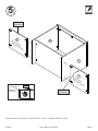
Fasten the ENDS (A and B) to the SMALL BOTTOMS (I). Tighten four HIDDEN CAMS.
Fasten four ANGLE BRACKETS (W) to the UPRIGHTS (C and D). Use four BLACK 9/16" LARGE HEAD SCREWS (DD).
C
D
I
I
Surface with
HIDDEN CAMS
Surface without
HIDDEN CAMS
Finished edge
Finished edge
A
B
BLACK 9/16” LARGE HEAD SCREW
(4 used for the ANGLE BRACKETS)
DD
W
W
Maximum
210 degrees
Minimum
190 degrees
Arrow

Page 11
www.sauder.com/services413043
7
7
S
t
e
p
C
D
A
B
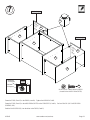
Fasten the TOPS (E and F) to the ENDS (A and B). Tighten four HIDDEN CAMS.
Fasten the TOPS (E and F) to the ANGLE BRACKETS on the UPRIGHTS (C and D). Use four BLACK 9/16" LARGE HEAD
SCREWS (DD).
Push the DOOR STOPS (X) into the holes in the TOPS (E and F).
F
E
Finished edge
Finished edge
X
Surface
with
holes
Surface
with
holes
BLACK 9/16” LARGE HEAD SCREW
(4 used for the ANGLE BRACKETS)
DD
Maximum
210 degrees
Minimum
190 degrees
Arrow

Page 12 www.sauder.com/services 413043
8
8
S
t
e
p
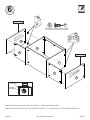
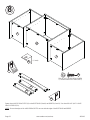
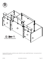
Fasten eleven ANGLE BRACKETS (W) to the BOTTOMS (H and I) and SKIRTS (O and P). Use eleven BLACK 9/16” LARGE
HEAD SCREWS (DD).
NOTE: Be sure the edges of the ANGLE BRACKETS are even with the edges of the BOTTOMS and SKIRTS.
I
I
H
O
P
P
BLACK 9/16” LARGE HEAD SCREW
(11 used for the ANGLE BRACKETS)
DD
W
W
W
(11 used)

Fasten the SKIRTS (O and P) to the ENDS (A and B), UPRIGHTS (C and D), and BOTTOMS (H and I). Use eleven BLACK 9/16"
LARGE HEAD SCREWS (DD).
Page 13
www.sauder.com/services413043
9
9
S
t
e
p
BLACK 9/16” LARGE HEAD SCREW
(11 used for the ANGLE BRACKETS)
DD
I
I
H
O
P
P
C
D
A
B

Page 14 www.sauder.com/services 413043
10
10
S
t
e
p
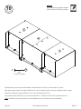
Carefully turn your unit over onto its front edges. Unfold the BACK (K) and lay it over the center of your unit.
Make equal margins along all four edges of the BACK (K). Push on opposite corners of your unit if needed to make it “square”.
Fasten the top and bottom edges of the BACK (K) to your unit using the NAILS (FF).
Next, fasten the SMALL BACKS (J) to your unit using the NAILS. The SMALL BACKS will overlap the BACK (K).
NOTE: Perforations have been provided for access through the BACKS. Carefully cut out the holes needed.
Do not stand the unit upright without the
BACK fastened. The unit may collapse.
Caution
NAIL
(52 used in this step)
FF
K
J
J

Page 15
www.sauder.com/services413043
11
11
S
t
e
p
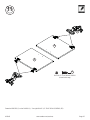
Fasten the HINGES (U) to the DOORS (L). Use eight BLACK 1/2" FLAT HEAD SCREWS (EE).
BLACK 1/2" FLAT HEAD SCREW
(8 used in this step)
EE
L
L
U
U

Page 16 www.sauder.com/services 413043
12
12
S
t
e
p
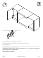
Carefully stand your unit upright.
Fasten a DOOR (L) to the LEFT END (B). Use the screws in the HINGES. See the next step for door adjustments.
NOTE: You may need to loosen the mounting screw and adjusting screw to slide them part way out of the slot. Retighten the screw
before you mount the HINGE to the MOLDING.
Fasten a PULL (V) to the DOOR (L). Use two SILVER 7/8" MACHINE SCREWS (CC).
Repeat this step for the other DOOR (L).
Mounting screw (depth)
Adjusting screw (horizontal)
V
L
B
SILVER 7/8" MACHINE SCREW
(4 used in this step)
CC

Page 17
www.sauder.com/services413043
13
13
S
t
e
p
Mounting screw (depth)
(vertical adjustment)
Adjusting screw (horizontal)
Refer to the enlarged diagram to identify the parts on the HINGES.
The DOORS may need some adjustments. Follow the text below to make needed adjustments.
DOOR ADJUSTMENTS:
To adjust the DOORS from side to side (horizontal), loosen the mounting screw several turns, then turn the adjusting screw in or out.
Tighten the mounting screw after making adjustments.
To adjust the DOORS up and down (vertical), loosen both vertical adjustment screws. Move the DOORS up or down to the desired
location. Tighten the screws after making adjustments.
To adjust the DOORS in or out (depth), loosen the mounting screw one turn and move the DOORS in or out, as needed. Tighten the
mounting screw after making adjustments.

Page 18 www.sauder.com/services 413043
14
14
S
t
e
p
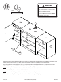
Push the RUBBER SLEEVES (AA) over the METAL PINS (Z). Insert the METAL PINS into the hole locations of your choice in the
ENDS (A and B) and UPRIGHTS (C and D). Set the ADJUSTABLE SHELVES (M and N) onto the METAL PINS.
Apply the WARNING LABEL (BB) to the TOP (G). You should be able to read the label when the TV is removed from the unit.
When the TV is in place, it should hide the label. Peel off the backing and apply the label as shown in the diagram.
NOTE: This is a permanent label intended to last for the life of the product. Once applied, do not try to remove it.
Push a CAM COVER (Y) onto each visible HIDDEN CAM.
NOTE: Please read the back pages of the instruction booklet for important safety information.
This completes assembly. Clean with your favorite furniture polish or a damp cloth. Wipe dry.
WARNING
Never use this furniture with a TV that is
too large or too heavy. Severe injury or
death can occur. The TV and furniture
will be unstable and may tip.
- The TV must weigh less than 135 lbs.
- The base of the TV must be able to sit
completely on this shelf.
BB
135 lbs.
B
G
A
D
C
To cover HIDDEN CAMS
(4 used)
Y
(16 used)
AA
Z
M
M
N
N
25 lbs.
25 lbs.
25 lbs.
25 lbs.
25 lbs.
25 lbs.
40 lbs.
35 lbs.
35 lbs.

A l’usage exclusif du
Canada Noter la date
d’achat de cet élément
et conserver le livret
pour future référence.
Pour contacter Sauder
en ce qui concerne cet
élément, faire référence
au numéro de lot et
numéro de modèle en
appelant notre numéro
sans frais.
Lot nº : ____________
Date de
l’achat: ____________
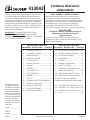
LISTE DE PIÈCES
REFERENCE DESCRIPTION QUANTITÉ
LISTE DE PIÈCES
REFERENCE DESCRIPTION QUANTITÉ
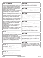
NOUS SOMMES LA POUR VOUS AIDER!
Nous faisons de notre mieux pour nous assurer que
votre meuble arrive dans d’excellentes conditions. Nos
représentants du service Clientèle sont aimables et prêts
à vous aider au cas où une pièce aurait été endommagée
ou manquerait (ou si vous aviez besoin d’aide pour
l’assemblage). NE RAMENEZ PAS LE MEUBLE AU
MAGASIN. Au Canada, composez ce numéro d’appel gratuit:
1-800-523-3987
Du lundi au vendredi, de 9 heures du matin à
5:30 heures du soir (horaire Côte Est)
(sauf jours fériés)
Si une pièce a besoin d’être remplacée, la pièce de
remplacement sera envoyée dans les 48 heures. (Sauf
week-ends et jours fériés)
Utilisez les instructions d’assemblage en français avec
les schémas étape par étape du manuel d’instruction
en anglais. Chaque étape en français correspond à la
même étape en anglais. La pièce devant être attachée
à l’élément est représentée en gris sur les schémas de
chaque étape pour plus de précision. Comparer la “Liste
de pièces” ci-dessous avec la “PART IDENTIFICATION”
du manuel en anglais pour vous familiariser avec les
pièces avant l’assemblage.
REMARQUE : CE MANUEL D’INSTRUCTIONS
CONTIENT D’IMPORTANTES INFORMATIONS
RELATIVES À LA SÉCURITÉ. À LIRE ET CONSERVER
POUR TOUTE RÉFÉRENCE FUTURE.
R2
EXCENTRIQUE ESCAMOTABLE
....23
S2 CHEVILLE D'EXCENTRIQUE .......20
T2 VIS D'EXCENTRIQUE .....................3
U CHARNIÈRE ....................................4
V POIGNÉE .........................................2
W CONSOLE À ÉQUERRE ...............15
X ARRÊT DE PORTE ..........................2
Y COUVERCLE D'EXCENTRIQUE ....4
Z GOUPILLE EN MÉTAL ..................16
AA MANCHON EN CAOUTCHOUC ....16
BB
ÉTIQUETTE DE MISE EN GARDE
....1
(Consulter la dernière étape pour
l'emplacement et application appropriées)
CC V
IS ARGENTÉE À MÉTAUX 22 mm
..4
DD
VIS NOIRE TÊTE LARGE 14 mm
....30
EE
VIS NOIRE TÊTE PLATE 13 mm
.......8
FF CLOU .............................................52
A EXTRÉMITÉ DROITE ......................1
B EXTRÉMITÉ GAUCHE ....................1
C MONTANT DROIT............................1
D MONTANT GAUCHE .......................1
E DESSUS DROIT ..............................1
F DESSUS GAUCHE ..........................1
G DESSUS ..........................................1
H DESSOUS .......................................1
I PETIT DESSOUS ............................2
J PETIT ARRIÈRE ..............................2
K ARRIÈRE .........................................1
L PORTE .............................................2
M GRANDE TABLETTE RÉGLABLE ...2
N TABLETTE RÉGLABLE ...................2
O PLINTHE CENTRALE ......................1
P PLINTHE LATÉRALE .......................2
Q MOULURE DE BUTÉE ....................1
Crédence télévision/
vidéo/stéréo
413043
Page 19
www.sauder.com/services413043

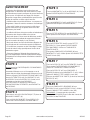
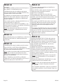
ÉTAPE 3
Fixer les MONTANTS (C et D) au DESSOUS (H). Serrer
quatre EXCENTRIQUES ESCAMOTABLES.
ÉTAPE 2
Faire tourner trois VIS D'EXCENTRIQUE (T2) dans la
MOULURE D'ARRÊT (Q).
Fixer la MOULURE D'ARRÊT (Q) au DESSUS (G).
Serrer trois EXCENTRIQUES ESCAMOTABLES.
ÉTAPE 1
Ne pas serrer les EXCENTRIQUES ESCAMOTABLES
dans cette étape.
Assembler l'élément sur un sol à moquette ou sur le
carton vide pour éviter d'endommager l'élément ou le sol.
Enfoncer vingt-trois EXCENTRIQUES ESCAMOTABLES (R2)
dans les EXTRÉMITÉS (A et B), les MONTANTS (C et D),
les DESSOUS (H et I) et le DESSUS (G). Ensuite,
insérer
l’extrémité en metal de la
vingt CHEVILLES
D'EXCENTRIQUE (S2) dans les EXCENTRIQUES
ESCAMOTABLES des EXTRÉMITÉS, des MONTANTS et
des DESSOUS.
ÉTAPE 5
Fixer les PETITS DESSOUS (I) aux MONTANTS (C et D).
Serrer quatre EXCENTRIQUES ESCAMOTABLES.
ÉTAPE 4
Fixer les MONTANTS (C et D) au DESSUS (G). Serrer
quatre EXCENTRIQUES ESCAMOTABLES.
ÉTAPE 6
Fixer les EXTRÉMITÉS (A et B) sur les PETITS
DESSOUS (I). Serrer quatre EXCENTRIQUES
ESCAMOTABLES. Utiliser un TOURNEVIS À
POINTE DROITE.
Fixer quatre CONSOLES À ÉQUERRE (W) aux
MONTANTS (C et D). Utiliser quatre VIS NOIRES TÊTE
LARGE 14 mm (DD).
ÉTAPE 7
Fixer les DESSUS (E et F) aux EXTRÉMITÉS (A et B).
Serrer quatre EXCENTRIQUES ESCAMOTABLES.
Utiliser un TOURNEVIS À POINTE DROITE.
Fixer les DESSUS (E et F) aux CONSOLES À
ÉQUERRE situées sur les MONTANTS (C et D). Utiliser
quatre VIS NOIRES TÊTE LARGE 14 mm (DD).
Enfoncer les ARRÊTS DE PORTE (X) dans les trous des
DESSUS (E et F).
ÉTAPE 8
Fixer onze CONSOLES À ÉQUERRE (W) aux
DESSOUS (H et I) et aux PLINTHES (O et P). Utiliser
onze VIS NOIRES TÊTE LARGE 14 mm (DD).
REMARQUE : S'assurer que les chants des
CONSOLES À ÉQUERRE sont à fl eur des chants des
DESSOUS et des PLINTHES.
Page 20 www.sauder.com/services 413043
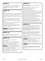
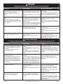
AVERTISSEMENT
L'utilisation d'un téléviseur trop lourd ou large est
dangereuse. Un téléviseur trop lourd créera un risque
de basculement pouvant provoquer de graves blessures
voire la mort. Un téléviseur trop large pour l'espace
disponible risque d'être accidentellement poussé ou de
tomber du mobilier ou d'être sujet à basculer.
•
Vérifi er la taille et le poids du téléviseur. Le comparer au
diagramme ci-dessous avant de commencer l'assemblage
!
• Cette unité Sauder est conçue pour les téléviseurs
pesant moins de 61 kg. Ne jamais utiliser avec des
téléviseurs plus lourds.
•
La taille du téléviseur, d'avant en arrière et latéralement,
doit rentrer dans l'espace défi ni sur le schéma.
• Ne jamais placer le chant avant du téléviseur au-delà
du chant avant de la tablette de support de téléviseur
(ou de la moulure de butée, le cas échéant).
• Ne jamais laisser les côtés du téléviseur dépasser les
chants latéraux de la surface de support du téléviseur.
• Si le téléviseur comporte un tube cathodique à image,
la robe du tube à image peut dépasser l'arrière de la
tablette de support.
• S'assurer d'apposer l'étiquette d'avertissement tel
qu'il l'est indiqué dans la dernière étape d'assemblage.
L'étiquette fournit d'importantes informations relatives à
la sécurité.
La page est en cours de chargement...
La page est en cours de chargement...
La page est en cours de chargement...
La page est en cours de chargement...
La page est en cours de chargement...
La page est en cours de chargement...
La page est en cours de chargement...
La page est en cours de chargement...
-
 1
1
-
 2
2
-
 3
3
-
 4
4
-
 5
5
-
 6
6
-
 7
7
-
 8
8
-
 9
9
-
 10
10
-
 11
11
-
 12
12
-
 13
13
-
 14
14
-
 15
15
-
 16
16
-
 17
17
-
 18
18
-
 19
19
-
 20
20
-
 21
21
-
 22
22
-
 23
23
-
 24
24
-
 25
25
-
 26
26
-
 27
27
-
 28
28


dans d''autres langues
- English: Sauder 413043 Operating instructions
- español: Sauder 413043 Instrucciones de operación
Documents connexes
-
Sauder 414239 Mode d'emploi
-
-
-
-
-
-
-
-
-