Hatco GRS, GRSB, GRSBF Series Le manuel du propriétaire
- Taper
- Le manuel du propriétaire

P/N 07.04.288.00 © 2019 Hatco Corporation
hatcocorp.com
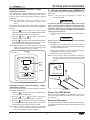
Register Online!
(see page 2)
S’inscrire en ligne!
(voir page 23)
Do not operate this equipment unless you
have read and understood the contents
of this manual! Failure to follow the
instructions contained in this manual
may result in serious injury or death.
This manual contains important safety
information concerning the maintenance,
use, and operation of this product. If
you’re unable to understand the contents
of this manual, please bring it to the
attention of your supervisor. Keep this
manual in a safe location for future
reference.
English = p 2
WARNING
No opere este equipo al menos que haya
leído y comprendido el contenido de este
manual! Cualquier falla en el seguimiento
de las instrucciones contenidas en
este manual puede resultar en un serio
lesión o muerte. Este manual contiene
importante información sobre seguridad
concerniente al mantenimiento, uso y
operación de este producto. Si usted
no puede entender el contenido de
este manual por favor pregunte a su
supervisor. Almacenar este manual en
una localización segura para la referencia
futura.
ADVERTENCIA
Ne pas utiliser cet équipement sans avoir
lu et compris le contenu de ce manuel ! Le
non-respect des instructions contenues
dans ce manuel peut entraîner de
graves blessures ou la mort. Ce manuel
contient des informations importantes
concernant l’entretien, l’utilisation et le
fonctionnement de ce produit. Si vous ne
comprenez pas le contenu de ce manuel,
veuillez le signaler à votre supérieur.
Conservez ce manuel dans un endroit
sûr pour pouvoir vous y référer plus tard.
Français = p 23
AVERTISSEMENT
Glo-Ray
®
Heated Shelf
Rayonnage Chauffant
GRS, GRSB, and GRSBF Series/Série
Installation and Operating Manual
Manuel d’installation et d’utilisation

English
Form No. GRSM-0719
2
CONTENTS
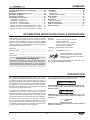
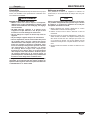
INTRODUCTION
Hatco Glo-Ray
©
Heated Shelves are designed to keep prepared
foods hot in kitchen work areas, server pick-up stations, or
customer serving points. Heated Shelves will keep all foods at
optimum serving temperatures without affecting quality. These
warmers have a thermostatically-controlled heated base to
extend the holding times of most foods.
Glo-Ray Heated Shelves are a product of extensive research
and field testing. The materials used were selected for maximum
durability, attractive appearance, and optimum performance.
Every unit is inspected and tested thoroughly prior to shipment.
This manual provides the installation, safety, and operating
instructions for the Glo-Ray Heated Shelf. Hatco recommends
all installation, operating, and safety instructions appearing in
this manual be read prior to installation or operation of the Glo-
Ray Heated Shelf.
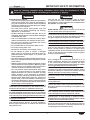
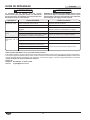
Safety information that appears in this manual is identified by
the following signal word panels:
WARNING
WARNING indicates a hazardous situation which, if not
avoided, could result in death or serious injury.
CAUTION
CAUTION indicates a hazardous situation which, if not
avoided, could result in minor or moderate injury.
NOTICE
NOTICE is used to address practices not related to
personal injury.
Important Owner Information ..............................................2
Introduction ...........................................................................2
Important Safety Information ..............................................3
Model Descriptions ..............................................................4
GRS Model .......................................................................... 4
GRSB and GRSBF Models .................................................4
Model Designation ...............................................................4
Specifications .......................................................................5
Plug Configurations .............................................................5
Dimensions — GRS Models ................................................5
Dimensions — GRSB Models .............................................6
Dimensions — GRSBF Models ........................................... 7
Electrical Rating Chart — GRS Models ..............................8
Electrical Rating Chart — GRSB Models .......................... 11
Electrical Rating Chart — GRSBF Models ........................12
Installation ...........................................................................13
General .............................................................................. 13
GRS Models ......................................................................13
GRSB and GRSBF Models ...............................................14
Operation .............................................................................17
General .............................................................................. 17
Maintenance ........................................................................18
General .............................................................................. 18
Daily Cleaning ...................................................................18
Troubleshooting Guide ......................................................19
Options and Accessories ..................................................20
Limited Warranty ................................................................22
Authorized Parts Distributors ...........................Back Cover
IMPORTANT OWNER INFORMATION
Record the model number, serial number, voltage, and
purchase date of the unit in the spaces below (specification
label on bottom of GRS model, bottom of control box on GRSB
and GRSBF models). Please have this information available
when calling Hatco for service assistance.
Model No. _______________________________________
Serial No. ________________________________________
Voltage __________________________________________
Date of Purchase __________________________________
Register your unit!
Completing online warranty registration will prevent delay in
obtaining warranty coverage. Access the Hatco website at
www.hatcocorp.com, select the Support pull-down menu,
and click on “Warranty”.
Business
Hours: 7:00 am to 5:00 pm Monday–Friday,
Central Time (CT)
(Summer Hours — June to September:
7:00 am to 5:00 pm Monday–Thursday
7:00 am to 4:00 pm Friday)
Telephone: 800-558-0607; 414-671-6350
E-mail: [email protected]
24 Hour 7 Day Parts and Service
Assistance available in the United States
and Canada by calling 800-558-0607.
Additional information can be found by visiting our web site at
www.hatcocorp.com.

English
Form No. GRSM-0719
3
IMPORTANT SAFETY INFORMATION
WARNING
ELECTRIC SHOCK HAZARD:
• Plug unit into a properly grounded electrical receptacle
of the correct voltage, size, and plug configuration. If
plug and receptacle do not match, contact a qualified
electrician to determine and install the proper voltage
and size electrical receptacle.
• Turn OFF power switch, unplug power cord, and
allow unit to cool before performing any cleaning,
adjustments, or maintenance.
• DO NOT submerge or saturate with water. Unit is not
waterproof. Do not operate if unit has been submerged
or saturated with water.
• Unit is not weatherproof. Locate unit indoors where
ambient air temperature is a minimum of 70°F (21°C).
• This unit is not “jet-proof” construction. Do not use
jet-clean spray to clean this unit.
• Do not steam clean or use excessive water on unit.
• Do not pull unit by power cord.
• Discontinue use if power cord is frayed or worn.
• Do not attempt to repair or replace a damaged
power cord. The cord must be replaced by Hatco, an
Authorized Hatco Service Agent, or a person with
similar qualifications.
• This unit must be serviced by qualified personnel only.
Service by unqualified personnel may lead to electric
shock or burn.
• Remote control enclosure must be mounted on vertical
wall and installed in vertical position. Mounting remote
control enclosure in horizontal position may result in
collection of liquids and lead to electric shock.
• Use only Genuine Hatco Replacement Parts when
service is required. Failure to use Genuine Hatco
Replacement Parts will void all warranties and may
subject operators of the equipment to hazardous
electrical voltage, resulting in electrical shock or burn.
Genuine Hatco Replacement Parts are specified to
operate safely in the environments in which they are
used. Some aftermarket or generic replacement parts
do not have the characteristics that will allow them to
operate safely in Hatco equipment.
FIRE HAZARD: Locate unit a minimum of 1″ (25 mm) from
combustible walls and materials. If safe distances are not
maintained, discoloration or combustion could occur.
Make sure food product has been heated to the proper
food-safe temperature before placing on the unit. Failure
to heat food product properly may result in serious health
risks. This unit is for holding preheated food product only.
Make sure all operators have been instructed on the safe
and proper use of the unit.
This unit is not intended for use by children or persons
with reduced physical, sensory, or mental capabilities.
Ensure proper supervision of children and keep them
away from the unit.
WARNING
This unit has no “user-serviceable” parts. If service
is required on this unit, contact an Authorized Hatco
Service Agent or contact the Hatco Service Department at
800-558-0607 or 414-671-6350.
CAUTION
BURN HAZARD: Some exterior surfaces on unit will get
hot. Use caution when touching these areas.
Locate unit at proper counter height in an area that is
convenient for use. The location should be level to prevent
unit or its contents from falling accidentally and strong
enough to support the weight of unit and contents.
Do not operate built-in models without control box
mounted properly as described in installation instructions.
Do not operate unit without installing supplied legs.
The National Sanitation Foundation (NSF) requires that
units over 36″ (914 mm) in width or weighing more than
80 lbs. (36 kg) either be sealed to or raised above
installation surface. If unit cannot be sealed at the point
of use, 4″ (102 mm) legs are included to allow for proper
cleaning access below unit.
NOTICE
Unit is designed and recommended for use in or on
metallic countertops. Damage to any countertop material
is not covered under the Hatco warranty. For other
surfaces, verify with manufacturer that material is suitable
for prolonged temperatures up to 200°F (93°C).
Do not modify wiring or cut thermostat capillary on control
enclosure to increase remote mounting distance. Cutting
thermostat capillary will cause unit to overheat and may
damage unit as well as surrounding countertop.
Do not use excessive force when tightening mounting
screws on built-in units. This may damage unit and/or
countertop.
Do not lay unit on the side with the control panel. Damage
to unit could occur.
Use non-abrasive cleaners and cloths only. Abrasive
cleaners and cloths could scratch the finish of the unit,
marring its appearance and making it susceptible to soil
accumulation.
Install remote mounted control enclosure outside of heat
zone. Locating control enclosure inside heat zone will
cause control(s) to overheat, malfunction, and fail.
Do not slide pans across hardcoat surface, use rough-
bottomed pans, or drop anything on hardcoat surface.
Scratching may occur. Damage to hardcoat surface caused
by misuse is not covered under warranty.
Do not locate unit in area with excessive air movement
around unit. Avoid areas that may be subject to active air
movements or currents (i.e., near exhaust fans/hoods, air
conditioning ducts, and exterior doors).
Read the following important safety information before using this equipment to avoid
serious injury or death and to avoid damage to equipment or property.

English
Form No. GRSM-0719
4
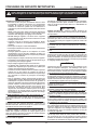
MODEL DESCRIPTION
MODEL DESIGNATION
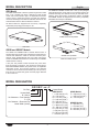
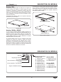
GRS Model
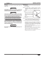
The GRS Heated Shelf is ideal for pass-through areas, buffet
lines, or as a heated work shelf. It features a Power On/Off
rocker switch with indicator light, an adjustable thermostat
control, and a 6′ (1829 mm) power cord with plug. Surface
mounted, blanket-type foil elements distribute heat under the
entire stainless steel or hardcoat aluminum surface.
All GRS models are shipped from the factory completely
assembled (except legs) and ready for use.
GRS Model
GRSB and GRSBF Models
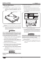
The GRSB and GRSBF Built-In Heated Shelves have a
hardcoat aluminum surface and a blanket-type foil element for
uniform heat distribution. Ideal for server-to-customer pass-
through areas, buffet/cafeteria lines, and other self-service
areas. The GRSB model features a recessed top. The GRSBF
model features a flat top.
A 36″ (914 mm) flexible conduit channels the power lines
from the shelf to a control box. The control box comes with an
illuminated POWER ON/OFF (I/O) rocker switch, an adjustable
thermostat control, and mounting brackets. The attached
control box can be mounted semi-remotely up to 36″ (914 mm)
from the unit. A 6′ (1829 mm) power cord and plug is attached
to the control box.
The GRSB and GRSBF models have a 3/4″ (19 mm) flanged
edge that allows the unit to drop into a countertop opening for
recessed mounting. The shelves are easy to clean with a non-
abrasive, damp cloth and/or non-abrasive cleaner. All GRSB
and GRSBF models are shipped from the factory completely
assembled and ready for installation.
GRSB Recessed Top Model
GRSBF Flat Top Model
GRSB and GRSBF Models
G R S B F - xx - F
Glo-Ray
®
Heated Shelf
B = Built-In
No Character = Free Standing
F = Flat
No Character = Recessed Top
Model Width (inches)
Heated Depth
GRSBF Models
F = 432 mm (17″)
I = 533 mm (21″)
S = 648 mm (25-1/2″)
O = 800 mm (31-1/2″)
GRSB Models
F = 394 mm (15-1/2″)
I = 495 mm (19-1/2″)
O = 762 mm (30″)
GRS Models
I = 495 mm(19-1/2″)
A = 152 mm (6″)
B = 197 mm (7-3/4″)
C = 248 mm (9-3/4″)
D = 305 mm (12″)
E = 349 mm (13-3/4″)
F = 394 mm (15-1/2″)
G = 400 mm (15-3/4″)
H = 445 mm (17-1/2″)
J = 546 mm (21-1/2″)
K = 597 mm (23-1/2″)
L = 648 mm (25-1/2″)

English
Form No. GRSM-0719
5
Footprint Footprint
Model Width (A) Depth (B) Height (C) Width (D) Depth (E)
GRS-18-I 18″ (457 mm) 19-1/2″ (495 mm) 2-1/4″ (57 mm) † 16-3/4″ (425 mm) 18″ (457 mm)
GRS-24-I 24″ (610 mm) 19-1/2″ (495 mm) 2-1/4″ (57 mm) † 22-3/4″ (578 mm) 18″ (457 mm)
GRS-30-I 30″ (762 mm) 19-1/2″ (495 mm) 2-1/4″ (57 mm) † 28-3/4″ (730 mm) 18″ (457 mm)
GRS-36-I 36″ (914 mm) 19-1/2″ (495 mm) 5-1/4″ (133 mm) * 34-3/4″ (883 mm) 18″ (457 mm)
GRS-42-I 42″ (1067 mm) 19-1/2″ (495 mm) 5-1/4″ (133 mm) * 40-3/4″ (1035 mm) 18″ (457 mm)
GRS-48-I 48″ (1219 mm) 19-1/2″ (495 mm) 5-1/4″ (133 mm) * 46-3/4″ (1187 mm) 18″ (457 mm)
GRS-54-I 54″ (1372 mm) 19-1/2″ (495 mm) 5-1/4″ (133 mm) * 52-3/4″ (1340 mm) 18″ (457 mm)
GRS-60-I 60″ (1524 mm) 19-1/2″ (495 mm) 5-1/4″ (133 mm) * 58-3/4″ (1492 mm) 18″ (457 mm)
GRS-66-I 66″ (1676 mm) 19-1/2″ (495 mm) 5-1/4″ (133 mm) * 64-3/4″ (1645 mm) 18″ (457 mm)
GRS-72-I 72″ (1829 mm) 19-1/2″ (495 mm) 5-1/4″ (133 mm) * 70-3/4″ (1797 mm) 18″ (457 mm)
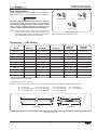
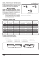
SPECIFICATIONS
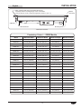
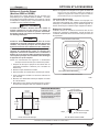
GRS Model Dimensions
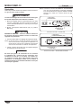
Plug Configurations
Units are supplied from the factory with an electrical cord and
plug installed. Plugs are supplied according to the application.
WARNING
ELECTRIC SHOCK HAZARD: Plug unit into a properly
grounded electrical receptacle of the correct voltage,
size, and plug configuration. If plug and receptacle do not
match, contact a qualified electrician to determine and
install the proper voltage and size electrical receptacle.
NOTE: The specification label is located on the bottom of GRS
models and the bottom of the remote control box on
GRSB and GRSBF models. See label for serial number
and verification of unit electrical information.
D
B
Front View Side View
A
C
E
NEMA 5-15P NEMA 5-20P
NEMA 6-15P
Plug Configurations
NOTE: Receptacle not supplied by Hatco.
Dimensions — GRS Models
NOTE:Allmodelslistedabovearebasedon19-1/2″(495mm)depth(I).Theadditionaldepthsavailableinclude:
A=6″(152mm) B=7-3/4″(197mm) C=9-3/4″(248mm) D=12″(305mm)
E=13-3/4″(349mm) F=15-1/2″(394mm) G=15-3/4″(400mm) H=17-1/2″(445mm)
J=21-1/2″(546mm) K=23-1/2″(597mm) L=25-1/2″(648mm)
† Height includes 1″ (25 mm) legs.
* Height includes 4″ (102 mm) legs.

English
Form No. GRSM-0719
6
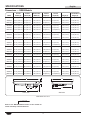
SPECIFICATIONS
A
B
C
F
G
Front View Side View
E
D
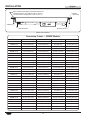
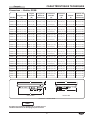
GRSB Model Dimensions
NOTICE
Refer to the INSTALLATION section of this manual for
actual countertop cutout dimensions.
Overall Heated Control Box Heated Overall Control Box
Model Width (A) Width (B) Width (C) Depth (D) Depth (E) Height (F) Height (G)
GRSB-24-F 25-1/2″ (648 mm) 24″ (610 mm) 7-1/4″ (184 mm) 15-1/2″ (394 mm) 17″ (432 mm) 2-7/8″ (73 mm) 2-1/8″ (54 mm)
GRSB-24-I 25-1/2″ (648 mm) 24″ (610 mm) 7-1/4″ (184 mm) 19-1/2″ (495 mm) 21″ (533 mm) 2-7/8″ (73 mm) 2-1/8″ (54 mm)
GRSB-24-O 25-1/2″ (648 mm) 24″ (610 mm) 7-1/4″ (184 mm) 30″ (762 mm) 31-1/2″ (800 mm) 2-7/8″ (73 mm) 2-1/8″ (54 mm)
GRSB-30-F 31-1/2″ (800 mm) 30″ (762 mm) 7-1/4″ (184 mm) 15-1/2″ (394 mm) 17″ (432 mm) 2-7/8″ (73 mm) 2-1/8″ (54 mm)
GRSB-30-I 31-1/2″ (800 mm) 30″ (762 mm) 7-1/4″ (184 mm) 19-1/2″ (495 mm) 21″ (533 mm) 2-7/8″ (73 mm) 2-1/8″ (54 mm)
GRSB-30-O 31-1/2″ (800 mm) 30″ (762 mm) 7-1/4″ (184 mm) 30″ (762 mm) 31-1/2″ (800 mm) 2-7/8″ (73 mm) 2-1/8″ (54 mm)
GRSB-36-F 37-1/2″ (953 mm) 36″ (914 mm) 7-1/4″ (184 mm) 15-1/2″ (394 mm) 17″ (432 mm) 2-7/8″ (73 mm) 2-1/8″ (54 mm)
GRSB-36-I 37-1/2″ (953 mm) 36″ (914 mm) 7-1/4″ (184 mm) 19-1/2″ (495 mm) 21″ (533 mm) 2-7/8″ (73 mm) 2-1/8″ (54 mm)
GRSB-36-O 37-1/2″ (953 mm) 36″ (914 mm) 7-1/4″ (184 mm) 30″ (762 mm) 31-1/2″ (800 mm) 2-7/8″ (73 mm) 2-1/8″ (54 mm)
GRSB-42-F 43-1/2″ (1105 mm) 42″ (1067 mm) 7-1/4″ (184 mm) 15-1/2″ (394 mm) 17″ (432 mm) 2-7/8″ (73 mm) 2-1/8″ (54 mm)
GRSB-42-I 43-1/2″ (1105 mm) 42″ (1067 mm) 7-1/4″ (184 mm) 19-1/2″ (495 mm) 21″ (533 mm) 2-7/8″ (73 mm) 2-1/8″ (54 mm)
GRSB-42-O 43-1/2″ (1105 mm) 42″ (1067 mm) 7-1/4″ (184 mm) 30″ (762 mm) 31-1/2″ (800 mm) 2-7/8″ (73 mm) 2-1/8″ (54 mm)
GRSB-48-F 49-1/2″ (1257 mm) 48″ (1219 mm) 7-1/4″ (184 mm) 15-1/2″ (394 mm) 17″ (432 mm) 2-7/8″ (73 mm) 2-1/8″ (54 mm)
GRSB-48-I 49-1/2″ (1257 mm) 48″ (1219 mm) 7-1/4″ (184 mm) 19-1/2″ (495 mm) 21″ (533 mm) 2-7/8″ (73 mm) 2-1/8″ (54 mm)
GRSB-48-O 49-1/2″ (1257 mm) 48″ (1219 mm) 7-1/4″ (184 mm) 30″ (762 mm) 31-1/2″ (800 mm) 2-7/8″ (73 mm) 2-1/8″ (54 mm)
GRSB-54-I 55-1/2″ (1410 mm) 54″ (1372 mm) 7-1/4″ (184 mm) 19-1/2″ (495 mm) 21″ (533 mm) 2-7/8″ (73 mm) 2-1/8″ (54 mm)
GRSB-60-F 61-1/2″ (1562 mm) 60″ (1524 mm) 7-1/4″ (184 mm) 15-1/2″ (394 mm) 17″ (432 mm) 2-7/8″ (73 mm) 2-1/8″ (54 mm)
GRSB-60-I 61-1/2″ (1562 mm) 60″ (1524 mm) 7-1/4″ (184 mm) 19-1/2″ (495 mm) 21″ (533 mm) 2-7/8″ (73 mm) 2-1/8″ (54 mm)
GRSB-60-O 61-1/2″ (1562 mm) 60″ (1524 mm) 7-1/4″ (184 mm) 30″ (762 mm) 31-1/2″ (800 mm) 2-7/8″ (73 mm) 2-1/8″ (54 mm)
GRSB-66-F 67-1/2″ (1715 mm) 66″ (1676 mm) 7-1/4″ (184 mm) 15-1/2″ (394 mm) 17″ (432 mm) 2-7/8″ (73 mm) 2-1/8″ (54 mm)
GRSB-66-I 67-1/2″ (1715 mm) 66″ (1676 mm) 7-1/4″ (184 mm) 19-1/2″ (495 mm) 21″ (533 mm) 2-7/8″ (73 mm) 2-1/8″ (54 mm)
GRSB-72-F 73-1/2″ (1867 mm) 72″ (1829 mm) 7-1/4″ (184 mm) 15-1/2″ (394 mm) 17″ (432 mm) 2-7/8″ (73 mm) 2-1/8″ (54 mm)
GRSB-72-I 73-1/2″ (1867 mm) 72″ (1829 mm) 7-1/4″ (184 mm) 19-1/2″ (495 mm) 21″ (533 mm) 2-7/8″ (73 mm) 2-1/8″ (54 mm)
GRSB-72-O 73-1/2″ (1867 mm) 72″ (1829 mm) 7-1/4″ (184 mm) 30″ (762 mm) 31-1/2″ (800 mm) 2-7/8″ (73 mm) 2-1/8″ (54 mm)
Dimensions — GRSB Models

English
Form No. GRSM-0719
7
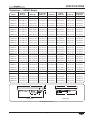
SPECIFICATIONS
A
B
C
F
G
Front View Side View
E
D
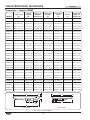
GRSBF Model Dimensions
Heated Control Box Heated Control Box
Model Width (A) Width (B) Width (C) Depth (D) Depth (E) Height (F) Height (G)
GRSBF-18-F 19-1/2″ (495 mm) 18-3/32″ (460 mm) 7-1/4″ (184 mm) 15-1/2″ (394 mm) 17″ (432 mm) 2-1/4″ (57 mm) 2-1/8″ (54 mm)
GRSBF-24-F 25-1/2″ (648 mm) 24-3/32″ (612 mm) 7-1/4″ (184 mm) 15-1/2″ (394 mm) 17″ (432 mm) 2-1/4″ (57 mm) 2-1/8″ (54 mm)
GRSBF-24-I 25-1/2″ (648 mm) 24-3/32″ (612 mm) 7-1/4″ (184 mm) 19-1/2″ (495 mm) 21″ (533 mm) 2-1/4″ (57 mm) 2-1/8″ (54 mm)
GRSBF-24-S 25-1/2″ (648 mm) 24-3/32″ (612 mm) 7-1/4″ (184 mm) 24″ (610 mm) 25-1/2″ (648 mm) 2-1/4″ (57 mm) 2-1/8″ (54 mm)
GRSBF-24-O 25-1/2″ (648 mm) 24-3/32″ (612 mm) 7-1/4″ (184 mm) 30″ (762 mm) 31-1/2″ (800 mm) 2-1/4″ (57 mm) 2-1/8″ (54 mm)
GRSBF-30-F 31-1/2″ (800 mm) 30-3/32″ (764 mm) 7-1/4″ (184 mm) 15-1/2″ (394 mm) 17″ (432 mm) 2-1/4″ (57 mm) 2-1/8″ (54 mm)
GRSBF-30-I 31-1/2″ (800 mm) 30-3/32″ (764 mm) 7-1/4″ (184 mm) 19-1/2″ (495 mm) 21″ (533 mm) 2-1/4″ (57 mm) 2-1/8″ (54 mm)
GRSBF-30-S 31-1/2″ (800 mm) 30-3/32″ (764 mm) 7-1/4″ (184 mm) 24″ (610 mm) 25-1/2″ (648 mm) 2-1/4″ (57 mm) 2-1/8″ (54 mm)
GRSBF-30-O 31-1/2″ (800 mm) 30-3/32″ (764 mm) 7-1/4″ (184 mm) 30″ (762 mm) 31-1/2″ (800 mm) 2-1/4″ (57 mm) 2-1/8″ (54 mm)
GRSBF-36-F 37-1/2″ (953 mm) 36-3/32″ (917 mm) 7-1/4″ (184 mm) 15-1/2″ (394 mm) 17″ (432 mm) 2-1/4″ (57 mm) 2-1/8″ (54 mm)
GRSBF-36-I 37-1/2″ (953 mm) 36-3/32″ (917 mm) 7-1/4″ (184 mm) 19-1/2″ (495 mm) 21″ (533 mm) 2-1/4″ (57 mm) 2-1/8″ (54 mm)
GRSBF-36-S 37-1/2″ (953 mm) 36-3/32″ (917 mm) 7-1/4″ (184 mm) 24″ (610 mm) 25-1/2″ (648 mm) 2-1/4″ (57 mm) 2-1/8″ (54 mm)
GRSBF-36-O 37-1/2″ (953 mm) 36-3/32″ (917 mm) 7-1/4″ (184 mm) 30″ (762 mm) 31-1/2″ (800 mm) 2-1/4″ (57 mm) 2-1/8″ (54 mm)
GRSBF-42-F 43-1/2″ (1105 mm) 42-3/32″ (1069 mm) 7-1/4″ (184 mm) 15-1/2″ (394 mm) 17″ (432 mm) 2-1/4″ (57 mm) 2-1/8″ (54 mm)
GRSBF-42-I 43-1/2″ (1105 mm) 42-3/32″ (1069 mm) 7-1/4″ (184 mm) 19-1/2″ (495 mm) 21″ (533 mm) 2-1/4″ (57 mm) 2-1/8″ (54 mm)
GRSBF-42-S 43-1/2″ (1105 mm) 42-3/32″ (1069 mm) 7-1/4″ (184 mm) 24″ (610 mm) 25-1/2″ (648 mm) 2-1/4″ (57 mm) 2-1/8″ (54 mm)
GRSBF-42-O 43-1/2″ (1105 mm) 42-3/32″ (1069 mm) 7-1/4″ (184 mm) 30″ (762 mm) 31-1/2″ (800 mm) 2-1/4″ (57 mm) 2-1/8″ (54 mm)
GRSBF-48-F 49-1/2″ (1257 mm) 48-3/32″ (1222 mm) 7-1/4″ (184 mm) 15-1/2″ (394 mm) 17″ (432 mm) 2-1/4″ (57 mm) 2-1/8″ (54 mm)
GRSBF-48-I 49-1/2″ (1257 mm) 48-3/32″ (1222 mm) 7-1/4″ (184 mm) 19-1/2″ (495 mm) 21″ (533 mm) 2-1/4″ (57 mm) 2-1/8″ (54 mm)
GRSBF-48-S 49-1/2″ (1257 mm) 48-3/32″ (1222 mm) 7-1/4″ (184 mm) 24″ (610 mm) 25-1/2″ (648 mm) 2-1/4″ (57 mm) 2-1/8″ (54 mm)
GRSBF-48-O 49-1/2″ (1257 mm) 48-3/32″ (1222 mm) 7-1/4″ (184 mm) 30″ (762 mm) 31-1/2″ (800 mm) 2-1/4″ (57 mm) 2-1/8″ (54 mm)
GRSBF-60-F 61-1/2″ (1562 mm) 60-3/32″ (1526 mm) 7-1/4″ (184 mm) 15-1/2″ (394 mm) 17″ (432 mm) 2-1/4″ (57 mm) 2-1/8″ (54 mm)
GRSBF-60-I 61-1/2″ (1562 mm) 60-3/32″ (1526 mm) 7-1/4″ (184 mm) 19-1/2″ (495 mm) 21″ (533 mm) 2-1/4″ (57 mm) 2-1/8″ (54 mm)
GRSBF-60-S 61-1/2″ (1562 mm) 60-3/32″ (1526 mm) 7-1/4″ (184 mm) 24″ (610 mm) 25-1/2″ (648 mm) 2-1/4″ (57 mm) 2-1/8″ (54 mm)
GRSBF-60-O 61-1/2″ (1562 mm) 60-3/32″ (1526 mm) 7-1/4″ (184 mm) 30″ (762 mm) 31-1/2″ (800 mm) 2-1/4″ (57 mm) 2-1/8″ (54 mm)
GRSBF-66-I 67-1/2″ (1715 mm) 66″ (1676 mm) 7-1/4″ (184 mm) 19-1/2″ (495 mm) 21″ (533 mm) 2-1/4″ (57 mm) 2-1/8″ (54 mm)
GRSBF-72-F 73-1/2″ (1867 mm) 72-3/32″ (1831 mm) 7-1/4″ (184 mm) 15-1/2″ (394 mm) 17″ (432 mm) 2-1/4″ (57 mm) 2-1/8″ (54 mm)
GRSBF-72-I 73-1/2″ (1867 mm) 72-3/32″ (1831 mm) 7-1/4″ (184 mm) 19-1/2″ (495 mm) 21″ (533 mm) 2-1/4″ (57 mm) 2-1/8″ (54 mm)
GRSBF-72-S 73-1/2″ (1867 mm) 72-3/32″ (1831 mm) 7-1/4″ (184 mm) 24″ (610 mm) 25-1/2″ (648 mm) 2-1/4″ (57 mm) 2-1/8″ (54 mm)
GRSBF-72-O 73-1/2″ (1867 mm) 72-3/32″ (1831 mm) 7-1/4″ (184 mm) 30″ (762 mm) 31-1/2″ (800 mm) 2-1/4″ (57 mm) 2-1/8″ (54 mm)
Dimensions — GRSBF Models

English
Form No. GRSM-0719
8
Model Voltage Watts Amps Plug Configuration Shipping Weight
GRS-18-I 120 250 2.1 NEMA 5-15P 16 lbs. (7 kg)
GRS-24-I 120 350 2.9 NEMA 5-15P 20 lbs. (9 kg)
GRS-30-I 120 450 3.8 NEMA 5-15P 25 lbs. (11 kg)
GRS-36-I 120 550 4.6 NEMA 5-15P 28 lbs. (13 kg)
GRS-42-I 120 600 5.0 NEMA 5-15P 32 lbs. (15 kg)
GRS-48-I 120 700 5.8 NEMA 5-15P 36 lbs. (16 kg)
GRS-54-I 120 800 6.7 NEMA 5-15P 42 lbs. (19 kg)
GRS-60-I 120 900 7.5 NEMA 5-15P 44 lbs. (20 kg)
GRS-66-I 120 1000 8.3 NEMA 5-15P 50 lbs. (23 kg)
GRS-72-I 120 1100 9.2 NEMA 5-15P 56 lbs. (25 kg)
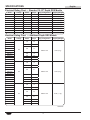
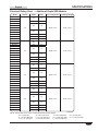
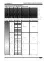
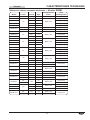
SPECIFICATIONS
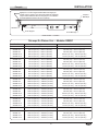
Electrical Rating Chart — Standard 19-1/2″ Depth GRS Models
Model Voltage Watts Amps Plug Configuration Shipping Weight
GRS-18-A
120
100 0.8
NEMA 5-15P 16 lbs. (7 kg)
GRS-18-B
GRS-18-C 125 1.0
GRS-18-D
200 1.7GRS-18-E
GRS-18-F
GRS-18-G
225 1.9
GRS-18-H
GRS-18-J 300 2.5
GRS-18-K 325 2.7
GRS-18-L 350 2.9
GRS-24-A
120
125 1.0
NEMA 5-15P 20 lbs. (9 kg)
GRS-24-B
GRS-24-C 175 1.5
GRS-24-D
250 2.1
GRS-24-E
GRS-24-F
GRS-24-G
300 2.5
GRS-24-H
GRS-24-J 375 3.1
GRS-24-K 425 3.5
GRS-24-L 475 4.0
GRS-30-A
120
150 1.3
NEMA 5-15P 25 lbs. (11 kg)
GRS-30-B
GRS-30-C 225 1.9
GRS-30-D
300 2.5
GRS-30-E
GRS-30-F
GRS-30-G
375 3.1
GRS-30-H
GRS-30-J 450 3.8
GRS-30-K 525 4.4
GRS-30-L 600 5.0
Electrical Rating Chart — Additional Depth GRS Models
continued...

English
Form No. GRSM-0719
9
Model Voltage Watts Amps Plug Configuration Shipping Weight
GRS-36-A
120
175 1.5
NEMA 5-15P 28 lbs. (13 kg)
GRS-36-B
GRS-36-C 275 2.3
GRS-36-D
350 2.9GRS-36-E
GRS-36-F
GRS-36-G
450 3.8
GRS-36-H
GRS-36-J 525 4.4
GRS-36-K 625 5.2
GRS-36-L 725 6.0
GRS-42-A
120
225 1.9
NEMA 5-15P 32 lbs. (15 kg)
GRS-42-B
GRS-42-C 300 2.5
GRS-42-D
450 3.8GRS-42-E
GRS-42-F
GRS-42-G
525 4.4
GRS-42-H
GRS-42-J 675 5.6
GRS-42-K 750 6.3
GRS-42-L 825 6.9
GRS-48-A
120
250 2.1
NEMA 5-15P 36 lbs. (16 kg)
GRS-48-B
GRS-48-C 350 2.9
GRS-48-D
500 4.2
GRS-48-E
GRS-48-F
GRS-48-G
600 5.0
GRS-48-H
GRS-48-J 750 6.3
GRS-48-K 850 7.1
GRS-48-L 950 7.9
GRS-54-A
120
275 2.3
NEMA 5-15P 42 lbs. (19 kg)
GRS-54-B
GRS-54-C 400 3.3
GRS-54-D
550 4.6GRS-54-E
GRS-54-F
GRS-54-G
675 5.6
GRS-54-H
GRS-54-J 825 6.9
GRS-54-K 950 7.9
GRS-54-L 1075 9.0
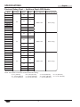
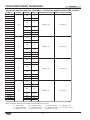
Electrical Rating Chart — Additional Depth GRS Models
NOTE: The last letter in the above models indicate the following depths:
A=6″(152mm) B=7-3/4″(197mm) C=9-3/4″(248mm) D=12″(305mm)
E=13-3/4″(349mm) F=15-1/2″(394mm) G=15-3/4″(400mm) H=17-1/2″(445mm)
J=21-1/2″(546mm) K=23-1/2″(597mm) L=25-1/2″(648mm)
continued...
SPECIFICATIONS

English
Form No. GRSM-0719
10
Model Voltage Watts Amps Plug Configuration Shipping Weight
GRS-60-A
120
300 2.5
NEMA 5-15P 44 lbs. (20 kg)
GRS-60-B
GRS-60-C 450 3.8
GRS-60-D
600 5.0GRS-60-E
GRS-60-F
GRS-60-G
750 6.3
GRS-60-H
GRS-60-J 900 7.5
GRS-60-K 1050 8.8
GRS-60-L 1200 10.0
GRS-66-A
120
325 2.7
NEMA 5-15P 50 lbs. (23 kg)
GRS-66-B
GRS-66-C 500 4.2
GRS-66-D
650 5.4GRS-66-E
GRS-66-F
GRS-66-G
825 6.9
GRS-66-H
GRS-66-J 975 8.1
GRS-66-K 1150 9.6
GRS-66-L 1325 11.0
GRS-72-A
120
350 2.9
NEMA 5-15P 56 lbs. (25 kg)
GRS-72-B
GRS-72-C 550 4.6
GRS-72-D
700 5.8GRS-72-E
GRS-72-F
GRS-72-G
900 7.5
GRS-72-H
GRS-72-J 1050 8.8
GRS-72-K 1250 10.4
GRS-72-L 1450 12.0
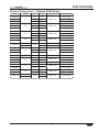
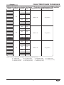
SPECIFICATIONS
Electrical Rating Chart — Additional Depth GRS Models
NOTE: The last letter in the above models indicate the following:
A=6″(152mm) B=7-3/4″(197mm) C=9-3/4″(248mm) D=12″(305mm)
E=13-3/4″(349mm) F=15-1/2″(394mm) G=15-3/4″(400mm) H=17-1/2″(445mm)
J=21-1/2″(546mm) K=23-1/2″(597mm) L=25-1/2″(648mm)

English
Form No. GRSM-0719
11
Model Voltage Watts Amps Plug Configuration Shipping Weight
GRSB-24-F
120
420 3.5
NEMA 5-15P
20 lbs. (9 kg)
GRSB-24-I 550 4.6 22 lbs. (10 kg)
GRSB-24-O 790 6.6 26 lbs. (12 kg)
GRSB-30-F
120
505 4.2
NEMA 5-15P
23 lbs. (10 kg)
GRSB-30-I 665 5.6 25 lbs. (11 kg)
GRSB-30-O 950 7.9 28 lbs. (13 kg)
GRSB-36-F
120
590 4.9
NEMA 5-15P
26 lbs. (12 kg)
GRSB-36-I 780 6.5 29 lbs. (13 kg)
GRSB-36-O 1110 9.3 32 lbs. (15 kg)
GRSB-42-F
120
685 5.7
NEMA 5-15P
29 lbs. (13 kg)
GRSB-42-I 885 7.4 32 lbs. (15 kg)
GRSB-42-O
120
1270
10.6 NEMA 5-15P 35 lbs. (16 kg)
208 6.1 NEMA 6-15P 35 lbs. (16 kg)
GRSB-48-F
120
770 6.4
NEMA 5-15P
33 lbs. (15 kg)
GRSB-48-I 1000 8.3 36 lbs. (16 kg)
GRSB-48-O 1430 11.9 39 lbs. (18 kg)
GRSB-54-I 120 1110 9.3 NEMA 5-15P 43 lbs. (20 kg)
GRSB-60-F
120
950 7.9
NEMA 5-15P
45 lbs. (20 kg)
GRSB-60-I 1220 10.2 50 lbs. (23 kg)
GRSB-60-O 1750 14.6 NEMA 5-20P 54 lbs. (24 kg)
GRSB-66-F
120
1040 8.7
NEMA 5-15P
50 lbs. (23 kg)
GRSB-66-I 1330 11.1 54 lbs. (25 kg)
GRSB-72-F
120
1130 9.4
NEMA 5-15P
52 lbs. (24 kg)
GRSB-72-I 1440 12.0 58 lbs. (26 kg)
GRSB-72-O
208
2070
10.0
NEMA 6-15P 64 lbs. (29 kg)
240 8.6
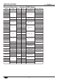
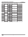
Electrical Rating Chart — Standard GRSB Models
SPECIFICATIONS

English
Form No. GRSM-0719
12
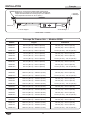
Model Voltage Watts Amps Plug Configuration Shipping Weight
GRSBF-18-F 120 330 2.8 NEMA 5-15P 15 lbs. (7 kg)
GRSBF-24-F
120
420 3.5
NEMA 5-15P
20 lbs. (9 kg)
GRSBF-24-I 550 4.6 22 lbs. (10 kg)
GRSBF-24-S 700 5.8 24 lbs. (11 kg)
GRSBF-24-O 790 6.6 26 lbs. (12 kg)
GRSBF-30-F
120 505 4.2 NEMA 5-15P 23 lbs. (10 kg)
208 505 2.4 NEMA 6-15P 23 lbs. (10 kg)
GRSBF-30-I
120
665 5.5
NEMA 5-15P
25 lbs. (11 kg)
GRSBF-30-S 825 6.9 26 lbs. (12 kg)
GRSBF-30-O 950 7.9 28 lbs. (13 kg)
GRSBF-36-F
120
590 4.9
NEMA 5-15P
26 lbs. (12 kg)
GRSBF-36-I 780 6.5 28 lbs. (13 kg)
GRSBF-36-S 950 7.9 31 lbs. (15 kg)
GRSBF-36-O 1110 9.3 32 lbs. (15 kg)
GRSBF-42-F
120
685 5.7
NEMA 5-15P
29 lbs. (13 kg)
GRSBF-42-I 885 7.4 32 lbs. (15 kg)
GRSBF-42-S 1100 9.2 34 lbs. (15 kg)
GRSBF-42-O 1270 10.6 35 lbs. (16 kg)
GRSBF-48-F
120
770 6.4
NEMA 5-15P
33 lbs. (15 kg)
GRSBF-48-I 1000 8.3 36 lbs. (16 kg)
GRSBF-48-S 1225 10.2 38 lbs. (17 kg)
GRSBF-48-O
120 1430 11.9 NEMA 5-15P
39 lbs. (18 kg)
240 1430 6.0 NEMA 6-15P
GRSBF-60-F 120 950 7.9
NEMA 5-15P
45 lbs. (20 kg)
GRSBF-60-I
120 1220 10.2 50 lbs. (23 kg)
208 1220 5.9 NEMA 6-15P 50 lbs. (23 kg)
GRSBF-60-S 120 1500 12.5 NEMA 5-20P 53 lbs. (24 kg)
GRSBF-60-O
120 1750 14.6 NEMA 5-20P
54 lbs. (25 kg)
240 1750 7.3 NEMA 6-15P
GRSBF-66-I
208
1330
6.4
NEMA 6-15P
54 lbs. (25 kg)
240 5.5 54 lbs. (25 kg)
GRSBF-72-F
120
1130 9.4
NEMA 5-15P
52 lbs. (24 kg)
GRSBF-72-I 1440 12.0 58 lbs. (26 kg)
GRSBF-72-S 1750 14.6 NEMA 5-20P 62 lbs. (28 kg)
GRSBF-72-O
208 2070 10.0 NEMA 6-15P
64 lbs. (29 kg)
240 2070 8.6 NEMA 6-15P
SPECIFICATIONS
Electrical Rating Chart — Standard GRSBF Models

English
Form No. GRSM-0719
13
INSTALLATION
General
Use the following procedures to install the GRS, GRSB, and
GRSBF units.
WARNING
FIRE HAZARD: Locate unit a minimum of 1″ (25 mm) from
combustible walls and materials. If safe distances are not
maintained, discoloration or combustion could occur.
CAUTION
Locate unit at proper counter height in an area that is
convenient for use. The location should be level to prevent
unit or its contents from falling accidentally and strong
enough to support the weight of unit and contents.
Do not operate built-in models without control box mounted
properly as described in the installation instructions.
Do not operate unit without installing supplied legs.
The National Sanitation Foundation (NSF) requires that
units over 36″ (914 mm) in width or weighing more than
80 lbs. (36 kg) either be sealed to or raised above the
installation surface. If unit cannot be sealed at the point
of use, 4″ (102 mm) legs are included to allow for proper
cleaning access below unit.
NOTICE
Do not operate unit prior to installing legs. Damage to unit
could occur.
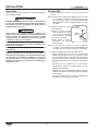
GRS Models
1. Remove the unit from the carton and place it upside down
on the cardboard.
NOTE: To prevent delay in obtaining warranty coverage,
complete online warranty registration. See the
IMPORTANT OWNER INFORMATION section for
details.
Foot
Stud
Rubber
Foot
2. Install the 1″ (25 mm) legs to the
unit.
a. Thread a foot stud into the
hole at each corner on the
bottom of the unit. Tighten
securely, but do not over-
tighten.
b. Slip a rubber foot over each
foot stud.
NOTE:If 4″ (102 mm) legs are
required, refer to the OPTIONS AND ACCESSORIES
section in this manual for installation instructions.
3. Turn unit upright, and place unit in the desired location.
• Locate the unit in an area where the ambient air
temperature is constant and a minimum of 70° F (21° C).
Avoid areas that may be subject to active air movements
or currents (i.e., near exterior doors, exhaust fans/
hoods, air conditioning ducts, etc...).
• Make sure the unit is at the proper counter height in an
area convenient for use.
• Make sure the countertop is level and strong enough to
support the weight of the unit and food product.
• Make sure all the feet on the bottom of the unit are
positioned securely on the countertop.

English
Form No. GRSM-0719
14
INSTALLATION
GRSB and GRSBF Models
1. Remove the unit from the carton and place it upside down
on the cardboard.
NOTE: To prevent delay in obtaining warranty coverage,
complete online warranty registration. See the
IMPORTANT OWNER INFORMATION section for
details.
Bracket Screw
Underside of GRSB Models
2. Remove and save the bracket screws from the underside
of the unit.
NOTE: The control box may be moved to the most convenient
location on the underside of the unit. For semi-remote
installations, leave the control box in place until the unit
is placed into the countertop.
NOTICE
Unit is designed and recommended for use in or on
metallic countertops. Damage to any countertop material
is not covered under the Hatco warranty. For other
surfaces, verify with manufacturer that material is suitable
for prolonged temperatures up to 200°F (93°C).
3. Prepare countertop opening. Refer to the appropriate
“Countertop Cutout” chart on the following pages for
recommended countertop cutout dimensions.
4. Apply a bead of NSF-approved sealant between the
countertop material and the mounting flange on the
unit. The sealant must be rated for use at a minimum
temperature of 250°F (121°C).
5. Place the unit into the countertop opening.
6. Assemble the Z-brackets to the underside of the unit using
the four bracket screws removed earlier in this procedure
(refer to the illustrations on the following pages).
NOTE:Units60″(1524mm)orlongerrequiretwoadditional
Z-brackets to be installed midway along the front and
rear of the unit.
7. Adjust the mounting screws on the Z-brackets until the top
flange lies flat on the countertop.
NOTICE
Do not use excessive force when tightening mounting
screws on built-in units. This may damage unit and/or
countertop.
8. Remove any excess sealant.
9. If desired or necessary, the control box can be mounted in
a semi-remote location.
a. Remove the control box from the bottom of the unit.
b. If necessary, remove the end brackets from the control
box, rotate/reposition, and re-secure to the control box.
c. The control box can be panel, surface, under counter, or
recess mounted.
Panel
Under Counter
Surface
7-1/4″
(184 mm)
2″
(51 mm)
2-1/8″
(54 mm)
7″
(178 mm)
Control Box Mounting Options
d. The distance the control box can be mounted from the
unit is determined by the 36″ (914 mm) conduit. Do not
pull the conduit tight to increase the mounting distance.
The conduit should have some slack after the control
box is mounted.
NOTICE
Do not modify wiring or cut thermostat capillary on control
enclosure to increase-remote mounting distance. Cutting
thermostat capillary will cause unit to overheat and may
damage unit as well as surrounding countertop.
10. Once all components are secured, proceed to the
OPERATION section.
NOTE:A 6′ (1829 mm) cord is supplied with this unit; any
excess cord should be routed neatly so it does not
hang down.

English
Form No. GRSM-0719
15
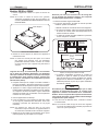
Bracket Screw
Metallic
Countertop
Mounting Screw
Z-Bracket
Apply a bead of NSF-approved sealant between the
countertop and the mounting flange on the unit. Sealant
must be rated for use at a minimum temperature of 250° F (121° C).
GRSB Model Installation
Countertop Cutout — GRSB Models
Model Minimum Width Maximum Width Minimum Depth Maximum Depth
GRSB-24-F 24-1/2″ (622 mm) 24-3/4″ (629 mm) 16″ (406 mm) 16-1/4″ (413 mm)
GRSB-24-I 24-1/2″ (622 mm) 24-3/4″ (629 mm) 20″ (508 mm) 20-1/4″ (514 mm)
GRSB-24-O 24-1/2″ (622 mm) 24-3/4″ (629 mm) 30-1/2″ (775 mm) 30-3/4″ (781 mm)
GRSB-30-F 30-1/2″ (775 mm) 30-3/4″ (781 mm) 16″ (406 mm) 16-1/4″ (413 mm)
GRSB-30-I 30-1/2″ (775 mm) 30-3/4″ (781 mm) 20″ (508 mm) 20-1/4″ (514 mm)
GRSB-30-O 30-1/2″ (775 mm) 30-3/4″ (781 mm) 30-1/2″ (775 mm) 30-3/4″ (781 mm)
GRSB-36-F 36-1/2″ (927 mm) 36-3/4″ (934 mm) 16″ (406 mm) 16-1/4″ (413 mm)
GRSB-36-I 36-1/2″ (927 mm) 36-3/4″ (934 mm) 20″ (508 mm) 20-1/4″ (514 mm)
GRSB-36-O 36-1/2″ (927 mm) 36-3/4″ (934 mm) 30-1/2″ (775 mm) 30-3/4″ (781 mm)
GRSB-42-F 42-1/2″ (1080 mm) 42-3/4″ (1086 mm) 16″ (406 mm) 16-1/4″ (413 mm)
GRSB-42-I 42-1/2″ (1080 mm) 42-3/4″ (1086 mm) 20″ (508 mm) 20-1/4″ (514 mm)
GRSB-42-O 42-1/2″ (1080 mm) 42-3/4″ (1086 mm) 30-1/2″ (775 mm) 30-3/4″ (781 mm)
GRSB-48-F 48-1/2″ (1232 mm) 48-3/4″ (1238 mm) 16″ (406 mm) 16-1/4″ (413 mm)
GRSB-48-I 48-1/2″ (1232 mm) 48-3/4″ (1238 mm) 20″ (508 mm) 20-1/4″ (514 mm)
GRSB-48-O 48-1/2″ (1232 mm) 48-3/4″ (1238 mm) 30-1/2″ (775 mm) 30-3/4″ (781 mm)
GRSB-54-I 54-1/2″ (1384 mm) 54-3/4″ (1391 mm) 20″ (508 mm) 20-1/4″ (514 mm)
GRSB-60-F 60-1/2″ (1537 mm) 60-3/4″ (1543 mm) 16″ (406 mm) 16-1/4″ (413 mm)
GRSB-60-I 60-1/2″ (1537 mm) 60-3/4″ (1543 mm) 20″ (508 mm) 20-1/4″ (514 mm)
GRSB-60-O 60-1/2″ (1537 mm) 60-3/4″ (1543 mm) 30-1/2″ (775 mm) 30-3/4″ (781 mm)
GRSB-66-F 66-1/2″ (1689 mm) 66-3/4″ (1696 mm) 16″ (406 mm) 16-1/4″ (413 mm)
GRSB-66-I 66-1/2″ (1689 mm) 66-3/4″ (1696 mm) 20″ (508 mm) 20-1/4″ (514 mm)
GRSB-72-F 72-1/2″ (1842 mm) 72-3/4″ (1848 mm) 16″ (406 mm) 16-1/4″ (413 mm)
GRSB-72-I 72-1/2″ (1842 mm) 72-3/4″ (1848 mm) 20″ (508 mm) 20-1/4″ (514 mm)
GRSB-72-O 72-1/2″ (1842 mm) 72-3/4″ (1848 mm) 30-1/2″ (775 mm) 30-3/4″ (781 mm)
INSTALLATION

English
Form No. GRSM-0719
16
Countertop Cutout — GRSBF Models
Model Minimum Width Maximum Width Minimum Depth Maximum Depth
GRSBF-18-F 18-1/2″ (470 mm) 18-3/4″ (476 mm) 16″ (406 mm) 16-1/4″ (413 mm)
GRSBF-24-F 24-1/2″ (622 mm) 24-3/4″ (629 mm) 16″ (406 mm) 16-1/4″ (413 mm)
GRSBF-24-I 24-1/2″ (622 mm) 24-3/4″ (629 mm) 20″ (508 mm) 20-1/4″ (514 mm)
GRSBF-24-S 24-1/2″ (622 mm) 24-3/4″ (629 mm) 24-1/2″ (622 mm) 24-3/4″ (629 mm)
GRSBF-24-O 24-1/2″ (622 mm) 24-3/4″ (629 mm) 30-1/2″ (775 mm) 30-3/4″ (781 mm)
GRSBF-30-F 30-1/2″ (775 mm) 30-3/4″ (781 mm) 16″ (406 mm) 16-1/4″ (413 mm)
GRSBF-30-I 30-1/2″ (775 mm) 30-3/4″ (781 mm) 20″ (508 mm) 20-1/4″ (514 mm)
GRSBF-30-S 30-1/2″ (775 mm) 30-3/4″ (781 mm) 24-1/2″ (622 mm) 24-3/4″ (629 mm)
GRSBF-30-O 30-1/2″ (775 mm) 30-3/4″ (781 mm) 30-1/2″ (775 mm) 30-3/4″ (781 mm)
GRSBF-36-F 36-1/2″ (927 mm) 36-3/4″ (934 mm) 16″ (406 mm) 16-1/4″ (413 mm)
GRSBF-36-I 36-1/2″ (927 mm) 36-3/4″ (934 mm) 20″ (508 mm) 20-1/4″ (514 mm)
GRSBF-36-S 36-1/2″ (927 mm) 36-3/4″ (934 mm) 24-1/2″ (622 mm) 24-3/4″ (629 mm)
GRSBF-36-O 36-1/2″ (927 mm) 36-3/4″ (934 mm) 30-1/2″ (775 mm) 30-3/4″ (781 mm)
GRSBF-42-F 42-1/2″ (1080 mm) 42-3/4″ (1086 mm) 16″ (406 mm) 16-1/4″ (413 mm)
GRSBF-42-I 42-1/2″ (1080 mm) 42-3/4″ (1086 mm) 20″ (508 mm) 20-1/4″ (514 mm)
GRSBF-42-S 42-1/2″ (1080 mm) 42-3/4″ (1086 mm) 24-1/2″ (622 mm) 24-3/4″ (629 mm)
GRSBF-42-O 42-1/2″ (1080 mm) 42-3/4″ (1086 mm) 30-1/2″ (775 mm) 30-3/4″ (781 mm)
GRSBF-48-F 48-1/2″ (1232 mm) 48-3/4″ (1238 mm) 16″ (406 mm) 16-1/4″ (413 mm)
GRSBF-48-I 48-1/2″ (1232 mm) 48-3/4″ (1238 mm) 20″ (508 mm) 20-1/4″ (514 mm)
GRSBF-48-S 48-1/2″ (1232 mm) 48-3/4″ (1238 mm) 24-1/2″ (622 mm) 24-3/4″ (629 mm)
GRSBF-48-O 48-1/2″ (1232 mm) 48-3/4″ (1238 mm) 30-1/2″ (775 mm) 30-3/4″ (781 mm)
GRSBF-60-F 60-1/2″ (1537 mm) 60-3/4″ (1543 mm) 16″ (406 mm) 16-1/4″ (413 mm)
GRSBF-60-I 60-1/2″ (1537 mm) 60-3/4″ (1543 mm) 20″ (508 mm) 20-1/4″ (514 mm)
GRSBF-60-S 60-1/2″ (1537 mm) 60-3/4″ (1543 mm) 24-1/2″ (622 mm) 24-3/4″ (629 mm)
GRSBF-60-O 60-1/2″ (1537 mm) 60-3/4″ (1543 mm) 30-1/2″ (775 mm) 30-3/4″ (781 mm)
GRSBF-66-I 66-1/2″ (1689 mm) 66-3/4″ (1696 mm) 20″ (508 mm) 20-1/4″ (514 mm)
GRSBF-72-F 72-1/2″ (1842 mm) 72-3/4″ (1848 mm) 16″ (406 mm) 16-1/4″ (413 mm)
GRSBF-72-I 72-1/2″ (1842 mm) 72-3/4″ (1848 mm) 20″ (508 mm) 20-1/4″ (514 mm)
GRSBF-72-S 72-1/2″ (1842 mm) 72-3/4″ (1848 mm) 24-1/2″ (622 mm) 24-3/4″ (629 mm)
GRSBF-72-O 72-1/2″ (1842 mm) 72-3/4″ (1848 mm) 30-1/2″ (775 mm) 30-3/4″ (781 mm)
INSTALLATION
Metallic
Countertop
Mounting Screw
Bracket Screw
Z-Bracket
Apply a bead of NSF-approved sealant between the
countertop and the unit. Sealant must be rated for
use at a minimum temperature of 250° F (121° C).
GRSBF Model Installation

English
Form No. GRSM-0719
17
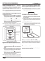
OPERATION
General
Use the following procedure to turn on and operate the GRS,
GRSB, and GRSBF units.
WARNING
Read all safety messages in the IMPORTANT SAFETY
INFORMATION section before operating this equipment.
1. Plug unit into a properly grounded electrical receptacle of
the correct voltage, size, and plug configuration. Refer to
the SPECIFICATIONS section in this manual for details.
2. Move the Power On/Off (I/O) switch to the On (I) position.
CAUTION
BURN HAZARD: Some exterior surfaces on unit will get
hot. Use caution when touching these areas.
3. Turn the thermostat control to the desired temperature
setting.
NOTE: Turning the thermostat control knob clockwise
will increase the temperature setting. Turning the
thermostat control knob counterclockwise will decrease
the temperature setting.
4. Allow the unit 30 minutes to reach operating temperature
NOTICE
Do not slide pans across hardcoat surface, use rough-
bottomed pans, or drop anything on hardcoat surface.
Scratching may occur. Damage to hardcoat surface
caused by misuse is not covered under warranty.
NOTE: Refer to the OPTIONS AND ACCESSORIES section
for installation and operation information for GRSB
and GRSBF units equipped with a flush-style remote
mounted control enclosure.
Thermostat
Control
Power On/Off
Switch
Control Panel — GRS Model
Thermostat
Control
Power I/O (on/off)
Switch
Control Panel — GRSB and GRSBF Models

English
Form No. GRSM-0719
18
MAINTENANCE
General
Hatco Glo-Ray
®
Heated Shelf units are designed for maximum
durability and performance with minimum maintenance.
WARNING
ELECTRIC SHOCK HAZARD:
• Turn OFF power switch, unplug power cord, and
allow unit to cool before performing any cleaning,
adjustments, or maintenance.
• DO NOT submerge or saturate with water. Unit is not
waterproof. Do not operate if unit has been submerged
or saturated with water.
• This unit is not “jet-proof” construction. Do not use
jet-clean spray to clean this unit.
• Do not steam clean or use excessive water on unit.
• Use only Genuine Hatco Replacement Parts when
service is required. Failure to use Genuine Hatco
Replacement Parts will void all warranties and may
subject operators of the equipment to hazardous
electrical voltage, resulting in electrical shock or burn.
Genuine Hatco Replacement Parts are specified to
operate safely in the environments in which they are
used. Some aftermarket or generic replacement parts
do not have the characteristics that will allow them to
operate safely in Hatco equipment.
This unit has no “user-serviceable” parts. If service
is required on this unit, contact an Authorized Hatco
Service Agent or contact the Hatco Service Department at
800-558-0607 or 414-671-6350.
Daily Cleaning
To preserve the finish of the Glo-Ray Heated Shelf, it is
recommended that all surfaces be cleaned daily
NOTICE
Use non-abrasive cleaners and cloths only. Abrasive
cleaners and cloths could scratch the finish of the unit,
marring its appearance and making it susceptible to soil
accumulation.
1. Turn off the unit, unplug the power cord, and allow the unit
to cool.
2. Remove and wash all food pans, if necessary.
3. Wipe down all metal surfaces with a non-abrasive, damp
cloth. Stubborn stains may be removed with a good
stainless steel or non-abrasive cleaner. Clean hard to
reach areas using a small brush and mild soap.
4. Wipe dry all surfaces using a non-abrasive, dry cloth.

English
Form No. GRSM-0719
19
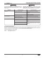
Symptom Probable Cause Corrective Action
Unit too hot. Thermostat control set too high. Adjust thermostat control to a lower setting.
Thermostat control stuck in the “on” position. Contact Authorized Service Agent or Hatco for
assistance.
Unit plugged into an incorrect power supply. Verify with qualified personnel that power supply
matches unit specification.
Unit not hot enough. Thermostat control set too low. Adjust thermostat control to a higher setting.
Location of unit is susceptible to air currents (air
conditioning ducts or exhaust fans).
Block air currents or relocate unit.
Unit not working at all. Unit not plugged in. Plug unit into proper power supply.
Unit not turned on. Move Power On/Off (I/O) switch to the On (I)
position.
Power On/Off (I/O) switch is not functioning.
Contact Authorized Service Agent or Hatco for
assistance.
Heating element is burned out.
Thermostat control is defective.
TROUBLESHOOTING GUIDE
WARNING
This unit must be serviced by qualified personnel only.
Service by unqualified personnel may lead to electric
shock or burn.
WARNING
ELECTRIC SHOCK HAZARD: Turn OFF power switch,
unplug power cord, and allow unit to cool before
performing any cleaning, adjustments, or maintenance.
Troubleshooting Questions?
If you continue to have problems resolving an issue, please contact the nearest Authorized Hatco Service Agency or Hatco for
assistance. To locate the nearest Service Agency, log onto the Hatco website at www.hatcocorp.com, select the Support pull-
down menu, and click on “Find A Service Agent”; or contact the Hatco Parts and Service Team at:
Telephone: 800-558-0607 or 414-671-6350
e-mail: [email protected]

English
Form No. GRSM-0719
20
OPTIONS AND ACCESSORIES
Remote Mounted Control Enclosures
(GRSB and GRSBF models)
Two flush-style remote mounted control enclosures are
available for the GRSB and GRSBF units — the mechanical
Thermostat Control enclosure and the digital Indicating
Temperature Control (ITC) enclosure. Both control enclosures
are installed using the following procedure.
WARNING
ELECTRIC SHOCK HAZARD: Remote control enclosure
must be mounted on vertical wall and installed in vertical
position. Mounting remote control enclosure in horizontal
position may result in collection of liquids and lead to
electric shock.
NOTICE
Do not install remote mounted control enclosure within
direct exposure to heat. Exposing the control enclosure
to direct heat will cause the control(s) to overheat,
malfunction, and fail.
Do not modify wiring or cut thermostat capillary on control
enclosure to increase semi-remote mounting distance.
Cutting thermostat capillary will cause unit to overheat and
may damage unit as well as surrounding countertop.
NOTE: A qualified electrician is recommended for connecting
the units to a power source.
1. Prepare cutout and pre-drill screw holes (see illustration
below for dimensions).
2. Remove trim cover from control enclosure.
3. Position control enclosure into opening through the
backside.
4. Secure control enclosure to surface using screws
(not supplied).
5. Connect proper power source to the mounted remote
control enclosure.
6. Reinstall the trim cover. Seal the trim cover to the mounting
surface with silicone adhesive.
NOTE:Unitsareequippedwitha36″(914mm)flexibleconduit
connecting the control enclosure to the unit. Optional
conduitlengthsof6′(1829mm)and10′(3048mm)are
also available for digital temperature controller only.
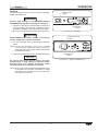
Power I/O (on/off) Switch
Both flush-style remote mounted control enclosures are
equipped with a Power I/O (on/off) switch. Move the Power
I/O (on/off) switch to the I (on) position to turn on the unit. The
indicator light in the switch glows when the unit is on.
Changing the Setpoint Temperature — Mechanical
Temperature Control
Turn the temperature control clockwise to increase the setpoint
temperature. Turn the temperature control counterclockwise to
decrease the setpoint temperature.
Thermostat Control
Power I/O (on/off) Switch
Mechanical Temperature Control
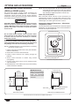
Remote Mounted Control Enclosure Installation Dimensions
Thermostat Enclosure
4″ (102 mm)
Digital Temperature Controller Enclosure
4-3/4″ (121 mm)
Mounting Surface
Trim Cover
Control Enclosure
Side View of Installed EnclosureFront View of Cutout
5-7/8″
(149 mm)
3-7/8″
(98 mm)
6-3/8″
(162 mm)
6-7/8″
(174 mm)
IMPORTANT NOTE:
Make sure the installation
location provides enough
room for electrical
connections to the control
enclosure.
La page est en cours de chargement...
La page est en cours de chargement...
La page est en cours de chargement...
La page est en cours de chargement...
La page est en cours de chargement...
La page est en cours de chargement...
La page est en cours de chargement...
La page est en cours de chargement...
La page est en cours de chargement...
La page est en cours de chargement...
La page est en cours de chargement...
La page est en cours de chargement...
La page est en cours de chargement...
La page est en cours de chargement...
La page est en cours de chargement...
La page est en cours de chargement...
La page est en cours de chargement...
La page est en cours de chargement...
La page est en cours de chargement...
La page est en cours de chargement...
La page est en cours de chargement...
La page est en cours de chargement...
La page est en cours de chargement...
La page est en cours de chargement...
-
 1
1
-
 2
2
-
 3
3
-
 4
4
-
 5
5
-
 6
6
-
 7
7
-
 8
8
-
 9
9
-
 10
10
-
 11
11
-
 12
12
-
 13
13
-
 14
14
-
 15
15
-
 16
16
-
 17
17
-
 18
18
-
 19
19
-
 20
20
-
 21
21
-
 22
22
-
 23
23
-
 24
24
-
 25
25
-
 26
26
-
 27
27
-
 28
28
-
 29
29
-
 30
30
-
 31
31
-
 32
32
-
 33
33
-
 34
34
-
 35
35
-
 36
36
-
 37
37
-
 38
38
-
 39
39
-
 40
40
-
 41
41
-
 42
42
-
 43
43
-
 44
44


Hatco GRS, GRSB, GRSBF Series Le manuel du propriétaire
- Taper
- Le manuel du propriétaire
dans d''autres langues
Documents connexes
-
Hatco GRS-48-C Glo-Ray 48″ Wide x 9 3/4″ Deep Stainless Steel Top Aluminum Base Free-Standing Manuel utilisateur
-
-
Hatco GRS-72-D Manuel utilisateur
-
Hatco GRS-36-B Manuel utilisateur
-
-
-
Hatco GRS-30-G Manuel utilisateur
-
Hatco GRS-42-J Manuel utilisateur
-
-