Tetra Contour Gen 2 Side-Bend Guide d'installation
- Taper
- Guide d'installation

Installation Guide
SIGN298 | DOC-2001570
Save These Instructions
Use only in the manner intended by the manufacturer.
If you have any questions, contact the manufacturer.
For the latest North American install guides for your product go to: https://products.LED.com/led-signage-lighting
For the latest European install guides for your product go to: https://products.LED.com/eu/led-signage-lighting
RETROFIT SIGN CONVERSION LED KIT FOR USE ONLY
IN ACCORDANCE WITH KIT INSTRUCTIONS.
KIT IS COMPLETE ONLY WHEN ALL PARTS REQUIRED
BY THE INSTRUCTIONS ARE PRESENT.
TROUSSE DE CONVERSION À DEL POUR LA
MODERNISATION DES ENSEIGNES
À UTILISER CONFORMÉMENT AU GUIDE D’INSTALLATION.
BG Българската версия на инструкциите за инсталаця и
информация за безопасност могат да бъдат намерени
на следния адрес: https://products.LED.com/eu/led-
signage-lighting
CS Návod k montáží a bezpečnostní informace v češtině
najdete zde: https://products.LED.com/eu/led-signage-
lighting
DA Den danske version af installationsvejledningen og
sikkerhedsoplysninger kan findes på følgende placering:
https://products.LED.com/eu/led-signage-lighting
DE Die deutsche Version der Installationsanleitung und
Sicherheitsinformationen finden Sie in folgendem Verzeic:
https://products.LED.com/eu/led-signage-lighting
EL Μπορείτε να βρείτε την ελληνική εκδχή των οδηγιών
νγκατάστασης και των πληροφοριών ασφάλειας στην
εξής τοποθεσία: https://products.LED.com/eu/led-
signage-lighting
ES La versión española de las instrucciones de instalación y
la información sobre seguridad puede encontrarse en la
siguiente ubicación: https://products.LED.com/eu/led-
signage-lighting
ET Eestikeelse paigaldusjuhendi ja ohutusnñuded leiate
aadressilt: https://products.LED.com/eu/led-signage-
lighting
FI Asennusohjeiden ja turvallisuustietojen suomenkielinen
versio löytyy seuraavasta paikasta: https://products.LED.
com/eu/led-signage-lighting
FR La version française des instructions d’installations et
information de sécurité est disponible à l’adresse suivante:
https://products.LED.com/eu/led-signage-lighting
HR Hrvatska verzija priručnika za ugradnju i sigurnosnih
informacija nalazi se na sljedečoj lokaciji: https://products.
LED.com/eu/led-signage-lighting
HU A telepítési útmutató és a biztnosági információk magyar
nyelvű változata az alábbi címen található: https://
products.LED.com/eu/led-signage-lighting
IT La versione italiana del manuale di installazione e
sicurezza può essere reperita nella seguente sezione:
https://products.LED.com/eu/led-signage-lighting
LT Lietuvišką diegimo instrukcijos ir saugos informacijos
versiją galima rasti šioje vietoje: https://products.LED.
com/eu/led-signage-lighting
LV Uzstādīšanas instrukciju un drošības informāciju latviešu
valodā var atrast šeit: https://products.LED.com/eu/led-
signage-lighting
NL De Nederlandse versie van de installatie-instructies en
veiligheidsinformatie kan op de volgende locatie worden
gevonden: https://products.LED.com/eu/led-signage-
lighting
PL Polską wersję instrukcji instalacji oraz informacje
dotyczące bezpieczeństwa można znaleźć w następującej
lokalizacji: https://products.LED.com/eu/led-signage-
lighting
PT A versão em Português das instruções de instalação e
das informações de segurança pode ser encontrada na
seguinte localização: https://products.LED.com/eu/led-
signage-lighting
RO Versiunea în limba română a instrucţiunilor de instalare
şi a informaţiilor de siguranţă pot fi găsite la: https://
products.LED.com/eu/led-signage-lighting
SV Ni hittar den svenska versionen av
installationsanvisningarna och säkerhetsinformationen på
följande plats: https://products.LED.com/eu/led-signage-
lighting
SL Previdnostna opozorila in varnostne informacije so na
zadnji strani vodnika za namestitev. Pred začetkom
namestitve izdelka jih skrbno preberite: https://products.
LED.com/eu/led-signage-lighting
SK Slovenskú verziu montažnej príručky a bezpečnostnŷch
instrukcií nájdete na nasledujúcej lokalite: https://
products.LED.com/eu/led-signage-lighting
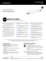
BEFORE YOU BEGIN
Read these instructions completely and carefully.
Prepare Electrical Wiring
Electrical Requirements
• Light engines without light guide limited to indoor dry locations.
• Light engines with light guide acceptable to use in dry, damp or
wet locations when installed correctly.
• The grounding and bonding of the LED Driver shall be done in
accordance with National Electric Code (NEC) Article 600.
• Follow all National Electric Codes (NEC) and local codes.
• These products are only suitable for connection to a circuit from
a Class 2 power source. These products have not been evaluated
for use when connected to a power source that does not comply
with Class 2 voltage and energy limited supplies.
FOR UL ONLY
2424
Volt
EN
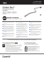
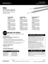
Contour Gen 2
LED Lighting System
Side Bend
GEXNS32-2, GEXNS65-2, GEXNSRD-2,
GEXNSGL-2, GEXNSBL-2, GEXNSYG-2,
GEXNSRC-2

Contour Gen 2 (Side Bend) Installation Guide
2
WARNING / AVERTISSEMENT
RISK OF ELECTRIC SHOCK
• Turn power off before inspection, installation or removal.
• Properly ground power supply enclosure.
RISK OF FIRE
• Use only suitably approved wire for input/output
connections. Minimum size 18 AWG (0.82mm2)
• Follow all local codes.
• Waterproof wire connection for outdoor or wet
installations. See instructions for details.
• Do not stretch light engines.
• Inspect and replace the light engines if any tear or
damage affects their integrity.
• Avoid installation that leads to prolonged exposure to
standing water or ice.
RISQUES DE DÉCHARGES ÉLECTRIQUES
• Coupez l’alimentation avant l’inspection, l’installation ou le déplacement.
• Assurez-vous de correctement mettre à terre l’alimentation
électrique.
RISQUES D’INCENDIE
• N’utilisez que des fils approuvés par UL pour les entrées/sorties de
connexion. Taille minimum 18 AWG (0.82mm2)
• Respectez tous les codes locaux.
• Étanchéifier les connexions électriques effectuées à l’extérieur
ou pour un environnement exposé à l’eau. Voir les instructions
d’installation pour plus de détails.
• Ne pas étirer les modules DEL Contour.
• Inspecter l’intégrité des modules DEL Contour et les remplacer s’ils
sont déchirés ou endommagés.
• Éviter les installations avec une exposition prolongée à l’eau
stagnante ou à la glace.
UL WARNING / AVERTISSEMENT UL
RISK OF FIRE OR ELECTRIC SHOCK
• LED Retrofit Kit installation requires knowledge of
sign electrical systems. If not qualified, do not attempt
installation. Contact a qualified electrician.
• Install this kit only in host signs that have been
identified in the installation instructions and where the
input rating of the retrofit kit does not exceed the input
rating of the sign.
• Installation of this LED retrofit kit may involve drilling or
punching of holes into the structure of the sign. Check
for enclosed wiring andcomponents to avoid damage to
wiring and electrical parts.
• Do not make or alter any open holes in an enclosure of
wiring or electrical components during kit installation.
RISQUE D’INCENDIE OU DE CHOC ÉLECTRIQUE
• L’installation de l’équipement de remplacement DEL exige Ia
connaissance des systèmes électriques pour enseignes. Si non qualifié, ne
tentez pas d’installation. Veuillez contacter un électricien qualifié.
• Risque d’incendie ou de choc électrique. Installez cet ensemble seulement
dans des enseignes hôtes qui ont été identifiés dans les instructions
d’installation et dont la capacité d’entrée de l’ensemble ne dépasse pas la
capacité d’entrée de l’enseigne.
• L’installation de cet équipement de remplacement DEL peut impliquer le
perçage ou le poinçonnage de trous dans la structure du panneau Vérifiez
le câblage et les composants inclus pour éviter d’endommager le câblage
et les composants électriques.
• Ne pas faire ou modifier les trous ouverts dans une enceinte de câblage
ou de composants électriques pendant l’installation de cet équipement
de remplacement DEL.
CAUTION / ATTENTION
RISK OF INJURY
• While performing installations described, gloves, safety
glasses or goggles should be worn.
RISQUE DE BLESSURE
• Lors de l’exécution des installations décrites, des gants, des lunettes de
sécurité ou des lunettes de protection doivent être portées.
This device complies with part 15 of the FCC Rules. Operation is subject to the following two conditions: (1) This device may not cause harmful interference,
and (2) this device must accept any interference received, including interference that may cause undesired operation.
Note: This equipment has been tested and found to comply with the limits for a Class A digital device, pursuant to part 15 of the FCC Rules. These limits
are designed to provide reasonable protection against harmful interference when the equipment is operated in a commercial environment. This equipment
generates, uses, and can radiate radio frequency energy and, if not installed and used in accordance with the instruction manual, may cause harmful
interference to radio communications. Operation of this equipment in a residential area is likely to cause harmful interference in which case the
user will be required to correct the interference at his own expense.
This Class [A] RFLD complies with the Canadian standard ICES-005. Ce DEFR de la classe [A] est conforme à la NMB-005 du Canada.

Contour Gen 2 (Side Bend) Installation Guide
3
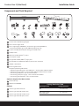
Components and Tools Required
1 2
3 4 5 6 7 8 9 10
Contour Gen 2 Side Bend Light Engine
Tetra® Contour Light Guide
Tetra® Light Engine (GEXNMCAC), Clear Plastic Light Guide (GEXNMC15),
or Stainless Steel Metal Light Guide (93053776) Mounting Clips.
#6, #8 or #10 (M2, M3 or M4) self-drilling pan headed screws
#6 (M2) screws
Minimum 22 AWG (0.33mm2) tie-wire
24 Volt power supply
UL approved 18 AWG (0.82mm2) supply wire
UL approved 22-14 AWG (0.33-2.08mm2) twist-on wire connectors
GEXNSL-2 Field Sleeve
Electrical grade silicone.
Examples of electrical grade silicone:
• Momentive RTV 6702 (white) / RTV 6708 (clear) - Silicone Rubber Adhesive Sealant
• Momentive RTV 162 (White) - Silicone Rubber Adhesive Sealant-Electrical Grade
• Dow Corning 3140 (clear) - Non-Corrosive Flowable
• Dow Corning 3145 (clear or gray) - Non-Corrosive Non-flowable
• Dow Corning RTV 748 (white) - Non-Corrosive Sealant
Tetra® End Caps
Weather box GEXNWB2
Contour Light Guide connector
Contour Light Guide 90° inside corner
Contour Light Guide 90° outside corner
Contour Light Guide 90° planar corner
Optional / Required for Wet Locations
Optional
12
14
16
13
15
17
11 16 17
12 13 14 15
23.8” (0.6m)
8 feet (2.44m)
Cutting Resolution Table
Light Engine Color Cutting Resolution
Red 4 in. (101.6 mm)
Red-Orange, Amber,
Green, Blue, White 3 in. (76.2 mm)
1
2
3
4
5
6
7
8
9
10
11

Contour Gen 2 (Side Bend) Installation Guide
4
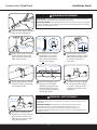
18 in. (457mm)
Install a minimum of one clip
per 18 in. (457mm) using #10
(M4) screws.
If cutting the light engine is
required, using the light guide
final length, measure out the
necessary length of Contour
Gen 2 LED light engine to
match.* Use a sharp cutting
tool to cut through light engine
(refer to the Cutting Resolution
Table on page 3).
Installation
Plan the layout by measuring the design layout and dividing by 8 ft . (2.44m) to determine the required quantity of
Contour Gen 2. Refer to the Cutting Resolution Table on page 3 when cutting any Contour Gen 2 section.
Do not use more than one suffix code for each respective application, as mixing suffix codes may result in
appearance variation. Suffix code can be found on the packaging label.
Installation methods shown are for straight runs. For custom shapes, refer to the Light Guide Forming Instructions.
DO NOT bend the light engine to an inside radius that is tighter than 1 in. (25.4 mm).
If you have any questions about these instructions or your specific Contour application, please contact support at
Planning First
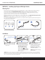
METHOD A - Installing Light Engines With Light Guides
1 2
NOTE: For back bends, please use Contour Gen 2 Back Bend (GEXNBxx-2) Light Engines
Mounting orientation if moisture
may accumulate inside light guide.
For cut end where the
GEXNSL-2 field sleeve is being
used, fill cap with electrical
grade silicone and push the
Field Sleeve on the end to seal.
Clean excess silicone.
NOTE: Not required if using the
plastic endcap.
3
Electrical
grade silicone
Cut on marks only
Side bend Back bend
*NOTE: When cut end is going to be installed in a Contour Light Guide Connector (strait or corner), the GEXNSL-2
Field Sleeve should be used. When using the eld sleeve, the light engine must be cut so that it will extend at least
1/2 in. (13 mm) out from the end of the light guide.

Contour Gen 2 (Side Bend) Installation Guide
5
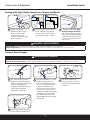
Insert wire connectors into
weather box. Fill with electrical
grade silicone and close box.
Weather box can be mounted
using #8 (M3) screws.
Apply caps to ends: fill cap with
electrical grade silicone and
push cap on the end to seal.
Clean excess silicone.
Weather box
can be painted
+
–
To connect two light engines,
first strip wire ends back 0.5
in. (13mm). Then join wires
together using twist-on wire
connectors.
Wires between light guide
segments can be folded
behind the light guide and
attached with clear zip ties.
Zip ties should wrap around
outside light guide.
Light guide
Wire loop Light engine (back)
WARNING / AVERTISSEMENT
RISK OF FIRE: Waterproof wire connection and all cut ends for outdoor or wet
installations. Weather box is required for all outdoor or wet locations electrical
connections.
RISQUE D’INCENDIE: Étanchéifier les connexions électriques et sceller
l’extrémité des sections coupées effectuées à l’extérieur ou pour un
environnement exposé à l’eau. Un boitier étanche est requis pour les
connexions électriques effectuées à l’extérieur ou dans un environnement avec
exposition à l’eau.
9
5
10
11
3/8in. (10mm)
Attach Contour Gen 2 to the
mountingclips, leaving a 3/8 in.
(10mm) gap between sections
to allow for expansion or
contraction.
For vertical or near vertical
installations, any cut-end
termination of a Contour
Gen 2 piece shall reside at
the top of the design.
Secure light guide by twisting
tie-wire around the mounting
clip and light guide.
6 7
8
Cut end
at top
Uncut
wiring at
bottom Fill both end caps with
silicone and install
WARNING/AVERTISSEMENT
RISK OF FIRE: The light engine is not intended for excessive or repetitive bending or
stretching. If the silicone does crack, replace the light engine.
RISQUE D’INCENDIE: Les modules DEL Contour ne sont pas conçus pour des pliages
excessifs, répétitifs ou pour être étirés. Si le silicone montre des signes de craquement,
remplacer le module DEL Contour.
Electrical grade
silicone
Push the light engine segments
down into the light guide.
4

Contour Gen 2 (Side Bend) Installation Guide
6
1 inch
bend radius
Light engine
Electrical grade
silicone
Linear: At each gap
between sections, apply
silicone on both sides
to secure light guide
connector. Snap on a light
guide connector.
Corner: For all corners (planar,
inside, outside) apply silicone
on both sides to secure light
guide corners. Snap on corner.
For bends, refer to the Light
Guide Forming Instructions
and first bend the light guide.
Once bent, carefully push light
engine into the light guide so
as to not to overly stretch the
light engine.
Joining with Light Guide Connectors, Corners and Bends
WARNING / AVERTISSEMENT
RISK OF FIRE: DO NOT bend the light engine to an inside radius that is tighter than 1 in. (25.4 mm).
RISQUE D’INCENDIE: Ne pas plier les modules DEL Contour avec un rayon de courbure inférieur à 1 pouce (25.4 mm).
12 13 14
Weather box can be painted
Insert wire connectors
into weather box. Fill with
electrical grade silicone and
close box.
Secure the weather box using
a #6 or #8 (M2 or M3) screw.
Power
supply
To Contour
Red (+)
Black or blue (–)
Strip wires back 0.5 in. (13mm).
Connect the gray wire (+)
from the LED strip to the red
wire (+) of the power supply.
Connect the white wire (-)
from the LED strip to the black
or blue wire (-) of the power
supply.Grounding and bonding
must be done in accordance
with National Electrical Code
(Article 600). See power supply
instructions.
Run a wire from the power
supply to a section of Contour
Gen 2. Power supply connection
must be completed in an
acceptable UL/NEMA enclosure.
Power supply loading is
described on page 10.
Connect Power Supply
17
18
WARNING/AVERTISSEMENT
RISK OF ELECTRICAL SHOCK: Turn power OFF before inspection, installation or removal.
RISQUES DE CHOC ÉLECTRIQUE: Coupez l’alimentation électrique avant d’inspecter, d’installer ou de déplacer le luminaire.
15 16
To power supply
Red (+)
White wire (–) Gray wire (+)
Black or blue (–)
Electrical
grade
silicone
Do not
bend one
light into a
corner

Contour Gen 2 (Side Bend) Installation Guide
7
6-12 in. (152-305 mm)
Plan the layout by measuring the
design layout and dividing by
8 ft . (2.44 m) to determine the
required quantity of Contour Gen 2.
Refer to the Cutting Resolution
Table on page 3 when cutting any
Tetra Contour Gen 2 section.
Do not use more than one suffix
code for each respective application,
as mixing suffix codes may result in
appearance variation. Suffix code
can be found on the packaging
label.
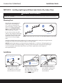
Installation methods shown are for straight runs. For custom shapes, install mounting clips at regular intervals
throughout the shape to provide adequate support for the light engine.
DO NOT bend the light engine to an inside radius that is tighter than 1 in. (25.4 mm). The light engine is not
intended for excessive or repetitive bending or stretching. If the silicone does crack, replace the light engine.
If you have questions about these instructions or your Contour application, contact support at
Planning First
WARNING / AVERTISSEMENT
RISK OF FIRE: Light engine by itself is intended for use in dry indoor application only.
RISQUES DE D’INCENDIE: Les modules DEL Contour utilisés seuls sont conçus pour les environnements intérieurs secs seulement.
METHOD B - Installing Light Engines Without Light Guides (Dry Indoor Only)
Install a mounting clip,
using #6 (M2) counter sink
screws, every 6-12 inches
(152-305 mm) on center until
the end of the run is reached.
Installation
Using the light engine final
length, measure out the
necessary length of Contour
Gen 2 light engine. If required,
using a sharp cutting tool, cut
through light engine.
For cut end, fill cap with
electrical grade silicone and
push GEXNSL-2 Field Sleeve
on the end to seal. Clean
excess silicone.
1 2 3
Electrical
grade silicone
Cut on marks only
NOTE: For back bends, please use Contour Gen 2 Back Bend (GEXNBxx-2) Light Engines
Side bend Back bend

Contour Gen 2 (Side Bend) Installation Guide
8
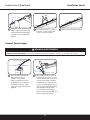
Push into clips +–
Power
supply
To Tetra Contour
Red (+)
Black or blue (-)
To power supply
Red (+)
Run a wire from the power
supply to a section of
Contour Gen 2. Power
supply connection must be
completed in an acceptable
UL/NEMA enclosure. Power
supply loading is described on
page 10.
Strip ends back 0.5 in. (13mm).
Connect the gray wire (+) from
the LED strip to the red wire (+)
of the power supply. Connect
the white wire (-) from the LED
strip to the black or blue wire (-)
of the power supply.Grounding
and bonding must be done
in accordance with National
Electrical Code (Article 600). See
power supply instructions.
Black or
blue (-)
Connect Power Supply
WARNING/AVERTISSEMENT
RISK OF ELECTRICAL SHOCK: Turn power OFF before inspection, installation or removal.
RISQUES DE CHOC ÉLECTRIQUE: Coupez l’alimentation électrique avant d’inspecter, d’installer ou de déplacer le luminaire.
7 8
Push each 24 in. (610 mm) light
engine segment into the clips.
Fold loose wires behind light
engines. Do not stretch light
engines.
Strip ends back 0.5 in. (13mm).
Use twist-on wire connectors
to join cut wires together.
Fold wires behind light engines.
5 6
4

Contour Gen 2 (Side Bend) Installation Guide
9
1. (Existing Signs Only) Prior to installation, survey the site for information regarding power and accessibility inside
and outside the building. Ensure that the branch circuit supplying the existing transformer or ballast will be within
the voltage ratings of the new LED power supply, and have a current rating not exceeding 20A, or that permitted by
applicable local, state, or country electrical codes (whichever is less).
2. (Existing Signs Only) Remove the existing lighting equipment to be replaced, such as neon tubing or fluorescent
tubes; and associated transformers and ballasts. Care should be taken not to break the existing neon or fluorescent
tubes. NOTE: Follow all federal and local regulations when disposing of neon tubing, fluorescent tubes, transformers
and ballasts.
3. (Existing Signs Only) If removal of the existing lighting equipment eliminates the disconnect switch, as required by
applicable local, state, or country electrical codes; a new disconnect switch must be installed.
4. (Existing Signs Only) Repair and seal any unused openings in the electrical enclosure. Openings greater than 12.7-
mm (1/2-in) diameter require a metal patch secured by screws or rivets and caulked with non-hardening caulk. Smaller
openings may be sealed with non-hardening caulk.
5. Using the layout guidelines above, determine required number of LED modules required to illuminate the sign.
6. A 24VDC Class 2 Power Supply, as listed below, must be used with this retrofit kit. Determine the number of Power
Supplies required to power the number of LED modules required to illuminate the sign, so as not to overload the Power
Supply chosen.
7. Follow Method A, B or C to mount the Contour Gen 2.
8. Connect the DC output of the power supply to the LED modules using the Electrical Connections instructions above.
9. Connect the power unit to the supply in accordance with the applicable local, state, and country electrical codes, and
the instructions found in the power supply installation guide.
10. If required, the disconnect switch shall be installed by qualified personnel, in accordance with applicable local, state,
and country electrical codes.
Retrofit Instructions
Troubleshooting
Symptom Condition Solution
All LEDs are OFF
No AC input. Attach AC input and/or check circuit breaker.
Incorrect wire attachment.
Check wire connection(s) at the Contour Gen 2 LED light engine
and power supply for improper connections or short circuits.
Make sure you have positive to positive and negative to
negative wire connections.
Some LEDs
appear dim
Overload (maximum load exceeded).
Ensure the overall length of Contour Gen 2 LED light engine does
not exceed the maximum load as detailed in the Tetra Power
Supply Installation Instructions.
Maximum recommended supply wire
length exceeded.
Reduce the length of supply wire equal to or below the
recommended maximum.
Mixed Suffix Codes of LED light engine
within an application.
Make sure that all LED light engines have the same Suffix Code
(Suffix Code is located on each packaging label).
Some of the
sections are not
illuminated
Incorrect wire attachment.
Check the wire connections at the Contour Gen 2 LED light
engine for improper connections. Make sure you have positive
to positive and negative to negative wire connections. Check for
improper cutting resolution locations (see table on Page 2).
Light/dark banding
along a section
LED light engine flexed in the wrong
direction or smaller than the minimum
bend radius during installation.
Remove LED light engine and properly install.
Inspect and replace light engine if damaged.

Contour Gen 2 (Side Bend) Installation Guide
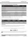
NOTE: For linear long runs, center connection to the LED strip is recommended to minimize voltage drop.
*GELP24-60U-GL minimum load = 11 ft. (3.35 m) for GEXNS32-2, GEXNS65-2, GEXNSGL-2, GEXNSBL-2, GEXNSYG-2,
and GEXNSRC-2 ; or 15 ft. (4.57 m) for GEXNSRD-2.
**GEPS24V50-100W minimum load = 27 ft. (8.23 m) for GEXNS32-2, GEXNS65-2, GEXNSGL-2, GEXNSBL-2, GEXNSYG-2,
and GEXNSRC-2 ; or 36 ft. (10.97 m) for GEXNSRD-2.
Maximum Loading per 24 VDC Class 2 Power Supply
Power Supply
GEXNS65-2, GEXNS32-2, GEXNSGL-2,
GEXNSBL-2, GEXNSYG-2, GEXNSRC-2 GEXNSRD-2
Rating per module 24VDC, 1.9W/ft. (Strip) 24VDC, 1.4W/ft. (Strip)
GEPS24-25U-NA, GEPS24-25-EU (CE only)
Load shall not exceed 0.83A 11 ft. (3.35 m) 15 ft. (4.57 m)
GEPS24D-60U-GLX, *GELP24-60U-GL
Load shall not exceed 2.5A 28 ft. (8.53 m) 39 ft. (11.88 m)
GEPS24D-80U
Load shall not exceed 3.3A 36 ft. (10.97 m) 49 ft. (14.93 m)
GEPS24-100U-GLX, GEPS24D-100U-NA , GEPS24LT-100U-NA,
USVI-100024FE, USVI-100024FBA
Load shall not exceed 4.0A
44 ft. (13.41 m) 59 ft. (17.98 m)
GEPS24-100U-GLX2, GEPS24-100U-TT, **GEPS24V50-100W
Load shall not exceed 4.0A 46 ft. (14.02 m) 62 ft. (18.89 m)
GEPS24-200U-GLX2
Load shall not exceed 4.0A per each (of 2) output channels
46 ft. (14.02 m) per bank
92 ft. (28.04 m) per PS 62 ft. (18.89 m) per bank
124 ft. (37.78 m) per PS
GEPS24-300U-GLX2
Load shall not exceed 4.0A per each (of 3) output channels
46 ft. (14.02 m) per bank
138 ft. (42.06 m) per PS 62 ft. (18.89 m) per bank
186 ft. (56.67 m) per PS
This product is intended solely for the use of non-residential signage lighting and is not intended for use in any other applications.
Conforms to the following standards:
Dismantling
At the end of life, the contained LED light source may be cut out using suitable wire cutters, removed from the mounting surface,
then replaced per the cutting and installation instructions above, or dismantled and taken to a communal collecting point for
environmentally friendly disposal in accordance with local regulations by a professional installer.
Electrical products must not be thrown out with domestic waste. They must be taken to a communal collecting point for environmentally friendly
disposal in accordance with local regulations. Contact your local authorities or stockist for advice on recycling. The packaging material is recyclable.
Dispose of the packaging in an environmentally friendly manner and make it available for the recyclable material collection-service.
Power Supply
Wattage
18 AWG/0.82 mm2
Supply Wire
16 AWG/1.31 mm2
Supply Wire
14 AWG/2.08 mm2
Supply Wire
12 AWG/3.31 mm2
Supply Wire
25W 20 ft./6.1 m –––
60W, 80W, 100W,
180W, 200W, 300W 20 ft./6.1 m 25 ft./7.6 m 35 ft./10.6 m 40 ft./12.1 m
Maximum Remote Mounting Distance from Driver Ouput
LED.com
© 2023 Current Lighting Solutions, LLC. All rights reserved. Information and specifications subject to change
without notice. All values are design or typical values when measured under laboratory conditions.
Page 10 of 10
(Rev 06/20/23)
SIGN298 | DOC-2001570
-
 1
1
-
 2
2
-
 3
3
-
 4
4
-
 5
5
-
 6
6
-
 7
7
-
 8
8
-
 9
9
-
 10
10


Tetra Contour Gen 2 Side-Bend Guide d'installation
- Taper
- Guide d'installation
dans d''autres langues
Documents connexes
-
Tetra Contour Gen 2 Back-Bend Guide d'installation
-
-
-
-
Tetra Slim EdgeStrip Guide d'installation
-
-
-
-
-
Autres documents
-
GE Appliances SIGN171 Guide d'installation
-
 Immersion GELP24-100U-GLX Power Supply Guide d'installation
-
GE current GEXNBL-1 Guide d'installation
-
Lumination Contour Series LED Architectural Lighting Guide d'installation
-
GE current GEXNB32-2 Guide d'installation
-
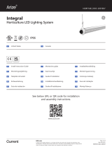 ARIZE Integral Guide d'installation
-
-
 Immersion Elite Gen 2 Vertical Case Center Mullion Lights Guide d'installation
-
 Immersion LED DIsplay Lighting Elite Series Horizontal Guide d'installation
-


