
1-Page_entete
WARNING
ATTENTION
A11 OFF
NON
*
HOOD
PIN
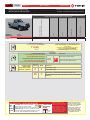
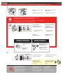
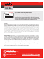
HOOD STATUS : THE HOOD PIN SWITCH (INCLUDED)
MUST BE INSTALLED IF THE VEHICLE CAN BE
REMOTE STARTED WITH THE HOOD OPEN, SET FUNCTION A11 TO OFF.
CONTACT
DE CAPOT
SECURITY STICKER
AUTOCOLLANT DE
SÉCURITÉ
MANDATORY INSTALL | INSTALLATION OBLIGATOIRE Notice: the installation of safety
elements are mandatory. The hood pin
and the sticker are essential security
elements and must be installed.
Notice: l'installation des éléments de
sécurité est obligatoire. Le contact de
capot et l'autocollant de sécurité sont
des éléments de sécurité essentiels et
doivent absolument être installés.
THIS MODULE MUST BE INSTALLED BY A
QUALIFIED TECHNICIAN. A WRONG
CONNECTION CAN CAUSE PERMANENT
DAMAGE TO THE VEHICLE.
CE MODULE DOIT ÊTRE INSTALLÉ PAR
UN TECHNICIEN QUALIFIÉ, TOUTE
ERREUR DANS LES BRANCHEMENTS
PEUT OCCASIONNER DES DOMMAGES
PERMANENTS AU VÉHICULE.
STATUT DE CAPOT : LE CONTACT DE CAPOT (INCLUS), DOIT ÊTRE
INSTALLÉ SI LE VÉHICULE PEUT DÉMARRER À DISTANCE, LORSQUE LE
CAPOT EST OUVERT, PROGRAMMEZ LA FONCTION A11 À NON.
Included
Inclus
ONE REV.: 20220114
ADDENDUM - SUGGESTED WIRING CONFIGURATION
ADDENDA - SCHÉMA DE BRANCHEMENT SUGGÉRÉ
Vehicle functions supported in this diagram (functional if equipped) | Fonctions du véhicule sup-
portées dans ce diagramme (fonctionnelles si équipé)
VEHICLE
VEHICULES
YEARS
ANNÉES
Immobilizer bypass
Contournement d’immobilisateur
Lock
Unlock
Parking Light
Foot-Brake Status
MAZDA
B-Serie 2002-2006 • • • • •
Guide # 87751
Program remote
starter option:
Programmez l’option
démarreur à distance:
FUNCTION
FONCTION MODE DESCRIPTION
22(+) Accessory 2 (E1)
(+) Accessoire 2 (E1)
20 2Tachless only. ( vehicles with automatic transmission only)
Sans Tachymètre seulement. (véhicules à transmission automatique
seulement)
Program bypass option
IF THE VEHICLE IS NOT EQUIPPED
WITH FUNCTIONAL HOOD PIN:
Programmez l’option du contournement
SI LE VÉHICULE N’EST PAS ÉQUIPÉ
D’UN CONTACT DE CAPOT FONCTIONNEL:
UNIT OPTION
OPTION UNITE DESCRIPTION
A11 OFF
NON
Hood trigger (Output Status).
Contact de capot (état de sortie).
BYPASS FIRMWARE VERSION
VERSION LOGICIELLE CONTOURNEMENT
To add the rmware version and the options, use the
FLASH LINK UPDATER or FLASH LINK MOBILE tool,
sold separately.
Pour ajouter la version logicielle et les options,
utilisez l’outil FLASH LINK UPDATER
ou FLASH LINK MOBILE, vendu séparément.
71.[44]
MINIMUM
Page 1 / 9
REGULAR INSTALLATION
INSTALLATION RÉGULIÈRE

This guide may change without notice. See www.fortin.ca for latest version.
Ce guide peut faire l’objet de changement sans préavis. Voir www.fortin.ca pour la récente version.
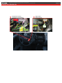
DESCRIPTION | DESCRIPTION
Ignition barrel
Barillet d'ignition
Transponder connector
Connecteur du transpondeur
(+)ACCESSORY2
(+)START
(+)IGNITION
(+)12V
TX
RX
(+)ACCESSORY1
Page 2 / 9

Yellow In A1
Purple Out A2
Purple/White Out A3
Green Out A4
White Out A5
Orange Out A6
Orange/Black Out A7
Dk.Blue Out A8
Red/Blue In A9
Lt.Blue/Black In/Out A10
Black In A11
Pink Out A12
Yellow/Black Out A13
Brown/White In A14
Pink/Black In A15
Purple/Yellow In/Out A16
Green/White In/Out A17
Green/Red In/Out A18
White/Black Out A19
Lt.Blue In/Out A20
C5 Brown
C4 Gray/Black
C3 Gray
C2 Orange/Brown
C1 Orange/Green
D6 White/Red
D5 White/Blue
D4 White/Green
D3 Yellow/Red
D2 Yellow/Blue
D1 Yellow/Green
White Out E1
Orange Out E2
Red In E3
Black In E4
Pink In/Out E5
Yellow Out E6
This guide may change without notice. See www.fortin.ca for latest version.
Ce guide peut faire l’objet de changement sans préavis. Voir www.fortin.ca pour la récente version.
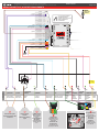
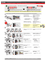
WIRING CONNECTION | GUIDE DE BRANCHEMENTS
CUT LOOP FOR AUTOMATIC
TRANSMISSION MODE.
COUPEZ LA BOUCLE POUR LE
MODE TRANSMISSION
AUTOMATIQUE.
(+)Starter
(+)Ignion
(-)Ground
(+)12V
(+)Accessory
(+)Accessory2
(~) TX
(-)Hood
(-)Parking Lights
(+)Foot Brake
(~) RX
(-)Unlock
(-)Lock
A2
A3
A4
A5
A6
A7
A8
A9
A10
A11
A12
A13
A14
A15
A16
A17
A18
A19
A20
E1
E2
E3
E4
E5
E6
C5
C4
C3
C2
C1
D6
D5
D4
D3
D2
D1
A1
D1
D2
D3
D4
C1
C2
C3
C4
C5
A19
A18
A17
A16
A14
A13
A9
A8
A7
A6
A5
A4
A1
A10 E5 E3E2 E6 E1
Fuse
Fusible
A20
Ground
Masse
HOOD PIN
MANDATORY
CONTACT CAPOT
OBLIGATOIRE
A3 A2 A11
A12
30
86
85
87
87a
Transponder
connector Green
connector (4-pins)
Back view
Connecteur du
transpondeur.
Connecteur Vert
(4-pins) Vue de dos
Grey/Orange
Gris/Orange White/Lt. Green
Blanc/Vert Pâle
Grey/
Pink
Gris/
Rose
Yellow
Jaune
Black/
Green
Noir/
Vert
Red/
Lt.Blue
Rouge/
Bleu Pâle
1
6
54
3
2
9
87
10 13
12
11
43
21
TXRX (+)IGNITION (+)12V
(+)
STARTER
(+)ACCES-
SORY1
Lt.Green/
Purple
Vert Pâle/
Mauve
(+)ACCES-
SORY2
At ignition barrel
Gray ignition
connector (13-pins)
Back view
Au barillet
d'ignition
connecteur gris
d'ignition (13-pins)
Vue de dos
3
3
Parking Lights
harness
Harnais des parking
lights
Brown
Brun
(+)PARKING
LIGHTS
B-SERIE
At Brake switch
Black connector
(2-pins) Back
view
Au commutateur
des freins
Connecteur Noir
(2-pins) Vue de
dos
Lt.Green
Vert Pâle
(+)BRAKE
4
4
At driver kick panel
Au panneau latéral côté
conducteur
(-)LOCK
Pink/Lt.Green
Rose/Vert Pâle
(-)UNLOCK
Pink/Yellow
Rose/Jaune
5
5
Guide # 87751 Page 3 / 9

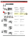
Release the programming
button when the LED is RED.
Insert the required remaining
connectors. Insérez les connecteurs
requis restants.
Relâchez le bouton de
programmation quand la DEL
est ROUGE.
The LEDs will alternate
between BLUE, RED, YELLOW
& BLUE/RED flashes.
Les DELS alterneront entre
un clignotement BLEU,
ROUGE, JAUNE &
BLEU/ROUGE.
LOCK
ACC ON
PUSH
START
IGN
TURN
ON/RUN
LOCK
ACC ON
START
IGN
ON Wait 3 seconds.
WAIT
3 SEC. Attendre 3 secondes.
Turn the first functIonal key to
the ON/RUN position. Tournez la première clé
fonctionnelle à la position
ON/RUN.
Turn the ignition to the OFF
position
and remove the first key.
Tournez la clé à la position
ARRÊT (OFF)
et retirez la clé du barillet.
LOCK
ACC ON
PUSH
START
IGN
TURN
ON/RUN Turn the second functIonal
key to the ON/RUN position. Tournez la deuxième clé
fonctionnelle à la position
ON/RUN.
LOCK
ACC ON
PUSH
START
OFF
TURN
OFF
LOCK
ACC ON
START
PUSHPUSH
REMOVE
KEY
LOCK
ACC ON
START
IGN
ON
WAIT
3 SEC.
Wait 3 seconds. Attendre 3 secondes.
KEY#1
CLÉ#1
KEY#2
CLÉ#2
CONTINUED NEXT PAGE | CONTINUEZ À LA PAGE SUIVANTE
If the LED is not solid RED
disconnect the 6 Pin
connector (Main-Harness)
and go back to step 1.
RELEASE
A
E
F
GJ
I
H
B
C
D
ON RED
ROUGE
Press and hold the
programming button:
Insert the 6-Pin Main connector.
Appuyez et maintenir le
bouton de programmation
enfoncé:
Insérez le connecteur
Principal à 6-broches.
Si le DEL n'est pas ROUGE
solide débranchez le
connecteur 6 pins
(Connecteur principal) et allez
à l'étape 1.
A
E
F
GJ
I
H
B
C
D
A
E
F
G
J
I
H
B
C
D
A
E
F
GJ
I
H
B
C
D
A
E
F
G
J
I
H
B
C
D
A
E
F
G
J
I
H
B
C
D
x1
HOLD
A
E
F
GJ
I
H
B
C
D
LED may differ depending on the module casing.
L’apparence des DELS peut différer selon le boîtier du module.
1
2
3
4
6
5
KEY#2
CLÉ#2
KEY#1
CLÉ#1
2 KEY REQUIRED
2 CLÉS REQUISES
This guide may change without notice. See www.fortin.ca for latest version.
Ce guide peut faire l’objet de changement sans préavis. Voir www.fortin.ca pour la récente version.
PROGRAM.1: 2 KEY PROGRAMMING PROCEDURE 1/2 | PROCÉDURE DE PROGRAMMATION AVEC 2 CLÉ 1/2
Page 4 / 9

LOCK
ACC ON
PUSH
START
OFF
TURN
OFF Turn the ignition to the OFF
position
and remove the second key.
Tournez la clé à la position
ARRÊT (OFF)
et retirez la clé du barillet.
LOCK
ACC ON
START
PUSHPUSH
REMOVE
KEY
The module is now
programmed.
Le module est
programmé.
Use the remote of the remote
starter or security system to test
all of the supported features to
ensure proper programming.
Testez toutes les fonctions
supportées sur le véhicule avec la
télécommande du démarreur à
distance ou du système de sécurité.
A
E
F
GJ
I
H
B
C
D
FLASH 10X
FLASH
10X OFF
If the LED is solid RED
disconnect the 4 Pin
connector (Data-Link) and go
back to step 1.
Si le DEL est ROUGE solide
débranchez le connecteur 4
pins (Data-Link) et allez à
l'étape 1.
The RED LED will flash
rapidly ten (10) times.
La DEL ROUGE clignotera dix
(10) fois rapidement.
8
5 sec. max
CAUTION The following step must be completed within 5 seconds.
Otherwise disconnect all connectors and go back to step 1.
ATTENTION les prochaines étapes doivent être complétées en moins de 5 secondes.
Si non, débranchez tous les connecteurs et allez à l'étape 1.
Press and hold the
programming button until
the LED flashes once.
x
x
1
1
PRESS
Pesez et garder appuyé
le bouton de
programmation jusqu'à se
que le DEL clignote une
fois.
The RED LED will flash
once (1x).
La DEL ROUGE
clignote 1 fois.
RELEASE
Release the
programming button.
Relâchez le bouton de
programmation.
Using a jumper wire,
apply power (12v) to the
vehicle's ignition1.
À l’aide d’un fil (jumper)
appliquez 12v sur
l’ignition1 du véhicule.
Ignition1
12V
Activate the remote
starter.
Actionnez le
démarreur à
distance.
AUTOMATIC TRANSMISSION
AUTOMATIQUETRANSMISSION MANUAL TRANSMISSION
MANUELLETRANSMISSION
9
Manual transmission:
Remove the jumper.
Transmission manuelle:
Retirez le fil (jumper).
PROGRAMMING PROCEDURE | PROCÉDURE DE PROGRAMMATION
7
CETTE PROGRAMMATION EST POUR LES
FORD / MAZDA
CETTE PROGRAMMATION EST POUR LES
FORD / MAZDA
A
E
F
GJ
I
H
B
C
D
OFF
ON
PRESS X1
OFF
ON
ON
A
E
F
GJ
I
H
B
C
D
This guide may change without notice. See www.fortin.ca for latest version.
Ce guide peut faire l’objet de changement sans préavis. Voir www.fortin.ca pour la récente version.
PROGRAM.1: 2 KEY PROGRAMMING PROCEDURE 2/2 | PROCÉDURE DE PROGRAMMATION AVEC 2 CLÉ 2/2
Page 5 / 9

Disconnect the 6-Pin (Main-
Harness) connector
and after all the remaining
connector.
7
Débranchez le connecteur 6-
pins (Connecteur principal) et
après tous les connecteurs du
EVO-ALL.
PROGRAMMING PROCEDURE WITH DCRYPTOR 2/3 | PROCÉDURE DE PROGRAMMATION AVEC DCRYPTOR 2/3
Release the programming
button when the LED is RED.
If the LED is not solid RED
disconnect the 6 Pin
connector (Main-Harness)
and go back to step 1.
Insert the required remaining
connectors.
8
9
10
11
Press and hold the
programming button:
Insert the 6-Pin Main connector.
Insérez les connecteurs requis
restants.
Appuyez et maintenir le
bouton de programmation
enfoncé:
Insérez le connecteur
Principal à 6-broches.
Relâchez le bouton de
programmation quand la DEL
est ROUGE.
Si le DEL n'est pas ROUGE
solide débranchez le
connecteur 6 pins
(Connecteur principal) et allez
à l'étape 1.
The LEDs will alternate
between BLUE, RED, YELLOW
& BLUE/RED flashes.
Les DELS alterneront entre
un clignotement BLEU,
ROUGE, JAUNE &
BLEU/ROUGE.
Press and release the
programming button once
(1x).
12
x
x
1
1
PRESS
Appuyez et relâchez 1 fois le
bouton de programmation.
WAIT
the RED LED will turn
OFF.
The YELLOW LED will turn
on.
ATTENDRE que l
a DEL
ROUGE s'éteigne.
La DEL JAUNE s'allume.
CONTINUED NEXT PAGE | CONTINUEZ À LA PAGE SUIVANTE
TRANSPONDER PROGRAMMING PROCEDURE | PROCÉDURE DE PROGRAMMATION DU TRANSPONDEUR
The RED LED will flash once. La DEL ROUGE clignote 1
fois.
Turn the Ignition to the
ON/RUN position.
Tournez la clé en position
ignition (ON).
LOCK
ACC ON
PUSH
START
IGN
O
O
N
N
IGN
A
E
F
GJ
I
H
B
C
D
A
E
F
GJ
I
H
B
C
D
A
E
F
GJ
I
H
B
C
D
A
E
F
GJ
I
H
B
C
D
RELEASE
A
E
F
GJ
I
H
B
C
D
ON RED
ROUGE
x
x
1
1
HOLD
A
E
F
GJ
I
H
B
C
D
LED may differ depending on the module casing.
L’apparence des DELS peut différer selon le boîtier du module.
A
E
F
GJ
I
H
B
C
D
A
E
F
GJ
I
H
B
C
D
A
E
F
GJ
I
H
B
C
D
A
E
F
GJ
I
H
B
C
D
A
E
F
GJ
I
H
B
C
D
OFF
ON
PRESS X1
OFF
ON
ON
A
E
F
GJ
I
H
B
C
D
IGNITION OFF IGNITION ON
OFF
ON
ON
A
E
F
GJ
I
H
B
C
D
15
Turn the Ignition to the
OFF position.
Tournez la clé à OFF.
LOCK
ACC ON
PUSH
START
OFF
13
14
The RED and YELLOW LEDs
will alternate.
La DEL ROUGE et JAUNE
alternent.
WAITthe YELLOW LED will
turn OFF.
ATTENDRE que la DEL
JAUNE s'éteigne.
Turn the Ignition to the
OFF position.
Tournez la clé à OFF.
Turn the Ignition to the
ON/RUN position.
Tournez la clé en position
ignition (ON).
LOCK
ACC ON
PUSH
START
IGN
LOCK
ACC ON
PUSH
START
OFF
O
O
F
F
F
F
IGN
O
O
N
N
IGN
OOFFFF
IGN
A
E
F
GJ
I
H
B
C
D
IGNITION ON IGNITION OFF
ON OFF
A
E
F
GJ
I
H
B
C
D
IGNITION OFF
ON
ON
FLASH RAPIDLY
Disconnect the 6-Pin (Main-
Harness) connector
and after all the remaining
connector.
7
Débranchez le connecteur 6-
pins (Connecteur principal) et
après tous les connecteurs du
EVO-ALL.
PROGRAMMING PROCEDURE WITH DCRYPTOR 2/3 | PROCÉDURE DE PROGRAMMATION AVEC DCRYPTOR 2/3
Release the programming
button when the LED is RED.
If the LED is not solid RED
disconnect the 6 Pin
connector (Main-Harness)
and go back to step 1.
Insert the required remaining
connectors.
8
9
10
11
Press and hold the
programming button:
Insert the 6-Pin Main connector.
Insérez les connecteurs requis
restants.
Appuyez et maintenir le
bouton de programmation
enfoncé:
Insérez le connecteur
Principal à 6-broches.
Relâchez le bouton de
programmation quand la DEL
est ROUGE.
Si le DEL n'est pas ROUGE
solide débranchez le
connecteur 6 pins
(Connecteur principal) et allez
à l'étape 1.
The LEDs will alternate
between BLUE, RED, YELLOW
& BLUE/RED flashes.
Les DELS alterneront entre
un clignotement BLEU,
ROUGE, JAUNE &
BLEU/ROUGE.
Press and release the
programming button once
(1x).
12
xx11
PRESS
Appuyez et relâchez 1 fois le
bouton de programmation.
WAIT
the RED LED will turn
OFF.
The YELLOW LED will turn
on.
ATTENDRE que l
a DEL
ROUGE s'éteigne.
La DEL JAUNE s'allume.
CONTINUED NEXT PAGE | CONTINUEZ À LA PAGE SUIVANTE
TRANSPONDER PROGRAMMING PROCEDURE | PROCÉDURE DE PROGRAMMATION DU TRANSPONDEUR
The RED LED will flash once. La DEL ROUGE clignote 1
fois.
Turn the Ignition to the
ON/RUN position.
Tournez la clé en position
ignition (ON).
LOCK
ACC ON
PUSH
START
IGN
OONN
IGN
A
E
F
GJ
I
H
B
C
D
A
E
F
GJ
I
H
B
C
D
A
E
F
GJ
I
H
B
C
D
A
E
F
GJ
I
H
B
C
D
RELEASE
A
E
F
GJ
I
H
B
C
D
ON RED
ROUGE
xx11
HOLD
A
E
F
GJ
I
H
B
C
D
LED may differ depending on the module casing.
L’apparence des DELS peut différer selon le boîtier du module.
A
E
F
GJ
I
H
B
C
D
A
E
F
GJ
I
H
B
C
D
A
E
F
GJ
I
H
B
C
D
A
E
F
GJ
I
H
B
C
D
A
E
F
GJ
I
H
B
C
D
OFF
ON
PRESS X1
OFF
ON
ON
A
E
F
GJ
I
H
B
C
D
IGNITION OFF IGNITION ON
OFF
ON
ON
A
E
F
GJ
I
H
B
C
D
15
Turn the Ignition to the
OFF position.
Tournez la clé à OFF.
LOCK
ACC ON
PUSH
START
OFF
13
14
The RED and YELLOW LEDs
will alternate.
La DEL ROUGE et JAUNE
alternent.
WAITthe YELLOW LED will
turn OFF.
ATTENDRE que la DEL
JAUNE s'éteigne.
Turn the Ignition to the
OFF position.
Tournez la clé à OFF.
Turn the Ignition to the
ON/RUN position.
Tournez la clé en position
ignition (ON).
LOCK
ACC ON
PUSH
START
IGN
LOCK
ACC ON
PUSH
START
OFF
OOFFFF
IGN
OONN
IGN
OOFFFF
IGN
A
E
F
GJ
I
H
B
C
D
IGNITION ON IGNITION OFF
ON OFF
A
E
F
GJ
I
H
B
C
D
IGNITION OFF
ON
ON
FLASH RAPIDLY
1
2
3
4
5
6
7
This guide may change without notice. See www.fortin.ca for latest version.
Ce guide peut faire l’objet de changement sans préavis. Voir www.fortin.ca pour la récente version.
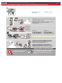
PROGRAM.3 DCRYPTOR PROGRAMMING PROCEDURE | PROCÉDURE DE PROGRAMMATION DCRYPTOR 1/2
Parts required (not included) Pièces requises (non incluses)
1x FLASH LINK UPDATER,
1x FLASH LINK MANAGER
1x FLASH LINK MOBILE
1x FLASH LINK MOBILE APP
SOFTWARE | PROGRAMME
Smartphone Android or iOS with Internet connection
(Internet provider charges may apply)
Téléphone Intelligent Android ou iOS avec connection
Internet (des frais du fournisseur Internet peuvent s’appliquer)
OR
OU
Microsoft Windows Computer with Internet connection
Ordinateur Microsoft Windows avec connection Internet
1x1x
BEFORE PROGRAMMING SET THE UNIT OPTIONS AND SAVE. | AVANT LA PROGRAMMATION CONFIGURER LES OPTIONS DE L'UNITÉ ET SAUVEGARDER.
PROGRAM.3 DCRYPTOR PROGRAMMING PROCEDURE | PROCÉDURE DE PROGRAMMATION DCRYPTOR 1/2
DCRYPTOR PROGRAMMING PROCEDURE 1/2 | PROCÉDURE DE PROGRAMMATION AVEC DCRYPTOR 1/2
Page 6 / 9

A
E
F
GJ
I
H
B
C
D
A
E
F
G
J
I
H
B
C
D
A
E
F
G
J
I
H
B
C
D
A
E
F
GJ
I
H
B
C
D
A
E
F
G
J
I
H
B
C
D
A
E
F
G
J
I
H
B
C
D
A
E
F
G
J
I
H
B
C
D
A
E
F
GJ
I
H
B
C
D
A
E
F
G
J
I
H
B
C
D
A
E
F
GJ
I
H
B
C
D
Disconnect all connectors and after the 6-Pin (Main-Harness)
or the 4-Pin Data-link connector.
Débranchez tous les connecteurs et ensuite le connecteur
6-pins (Connecteur principal) ou le connecteur
4-pins (Data-Link).
REMOTE STARTER / ALARM VERIFICATION
PROCEDURE | PROCÉDURE DE VÉRIFICATION
DU DÉMARREUR À DISTANCE / ALARME
The module is now programmed.
Le module est programmé. Test the remote starter. Remote start the vehicle.
Testez le démarreur à distance. Démarrez le véhicule
à distance.
AFTER DCRYPTOR PROGRAMMING COMPLETED
Go back to the vehicle and reconnect the 6-Pin (Main-
Harness) or the 4-pins (Data-Link) connector
and after all the remaining connector.
APRÈS LA PROCÉDURE DE PROGRAMMATION
DCRYPTOR COMPLETÉE : retournez au véhicule et
rebranchez le connecteur 6-pins (Connecteur principal)
ou le 4-pins (Data-Link) et après tous les connecteurs.
FLASH LINK UPDATER*
FLASH LINK MOBILE*
FLASH LINK MANAGER*
SOFTWARE | PROGRAMME
A
E
F
GJ
I
H
B
C
D
A
E
F
GJ
I
H
B
C
D
Microsoft Windows
Computer with
Internet connection*
Ordinateur Microsoft
Windows avec
connection Internet*
*Pièces requises (non incluses)
Use the tool:
FLASH LINK UPDATER or
FLASH LINK MOBILE
to visit the DCryptor menu.
Utilisez l'outil:
FLASH LINK UPDATER ou
FLASH LINK MOBILE
pour visiter le menu DCryptor.
*Parts required (not included)
VEHICLE'S OBDII
CONNECTOR
CONNECTEUR OBDII
DU VÉHICULE
OR
OU Smartphone*
(Internet provider
charges
may apply)
Téléphone
Intelligent*
(des frais du
fournisseur
Internet peuvent
s’appliquer)
Disconnect the 6-Pin (Main-
Harness) connector
and after all the remaining
connector.
7
Débranchez le connecteur 6-
pins (Connecteur principal) et
après tous les connecteurs du
EVO-ALL.
PROGRAMMING PROCEDURE WITH DCRYPTOR 2/3 | PROCÉDURE DE PROGRAMMATION AVEC DCRYPTOR 2/3
Release the programming
button when the LED is RED.
If the LED is not solid RED
disconnect the 6 Pin
connector (Main-Harness)
and go back to step 1.
Insert the required remaining
connectors.
8
9
10
11
Press and hold the
programming button:
Insert the 6-Pin Main connector.
Insérez les connecteurs requis
restants.
Appuyez et maintenir le
bouton de programmation
enfoncé:
Insérez le connecteur
Principal à 6-broches.
Relâchez le bouton de
programmation quand la DEL
est ROUGE.
Si le DEL n'est pas ROUGE
solide débranchez le
connecteur 6 pins
(Connecteur principal) et allez
à l'étape 1.
The LEDs will alternate
between BLUE, RED, YELLOW
& BLUE/RED flashes.
Les DELS alterneront entre
un clignotement BLEU,
ROUGE, JAUNE &
BLEU/ROUGE.
Press and release the
programming button once
(1x).
12
xx11
PRESS
Appuyez et relâchez 1 fois le
bouton de programmation.
WAIT
the RED LED will turn
OFF.
The YELLOW LED will turn
on.
ATTENDRE que l
a DEL
ROUGE s'éteigne.
La DEL JAUNE s'allume.
CONTINUED NEXT PAGE | CONTINUEZ À LA PAGE SUIVANTE
TRANSPONDER PROGRAMMING PROCEDURE | PROCÉDURE DE PROGRAMMATION DU TRANSPONDEUR
The RED LED will flash once. La DEL ROUGE clignote 1
fois.
Turn the Ignition to the
ON/RUN position.
Tournez la clé en position
ignition (ON).
LOCK
ACC ON
PUSH
START
IGN
OONN
IGN
A
E
F
GJ
I
H
B
C
D
A
E
F
GJ
I
H
B
C
D
A
E
F
GJ
I
H
B
C
D
A
E
F
GJ
I
H
B
C
D
RELEASE
A
E
F
GJ
I
H
B
C
D
ON RED
ROUGE
xx11
HOLD
A
E
F
GJ
I
H
B
C
D
LED may differ depending on the module casing.
L’apparence des DELS peut différer selon le boîtier du module.
A
E
F
GJ
I
H
B
C
D
A
E
F
GJ
I
H
B
C
D
A
E
F
GJ
I
H
B
C
D
A
E
F
GJ
I
H
B
C
D
A
E
F
GJ
I
H
B
C
D
OFF
ON
PRESS X1
OFF
ON
ON
A
E
F
GJ
I
H
B
C
D
IGNITION OFF IGNITION ON
OFF
ON
ON
A
E
F
GJ
I
H
B
C
D
15
Turn the Ignition to the
OFF position.
Tournez la clé à OFF.
LOCK
ACC ON
PUSH
START
OFF
13
14
The RED and YELLOW LEDs
will alternate.
La DEL ROUGE et JAUNE
alternent.
WAITthe YELLOW LED will
turn OFF.
ATTENDRE que la DEL
JAUNE s'éteigne.
Turn the Ignition to the
OFF position.
Tournez la clé à OFF.
Turn the Ignition to the
ON/RUN position.
Tournez la clé en position
ignition (ON).
LOCK
ACC ON
PUSH
START
IGN
LOCK
ACC ON
PUSH
START
OFF
OOFFFF
IGN
OONN
IGN
O
O
F
F
F
F
IGN
A
E
F
GJ
I
H
B
C
D
IGNITION ON IGNITION OFF
ON OFF
A
E
F
GJ
I
H
B
C
D
IGNITION OFF
ON
ON
FLASH RAPIDLY
8
9
10
11
This guide may change without notice. See www.fortin.ca for latest version.
Ce guide peut faire l’objet de changement sans préavis. Voir www.fortin.ca pour la récente version.
KEY BYPASS PROGRAMMING PROCEDURE 2/2 | PROCÉDURE DE PROGRAMMATION CONTOURNEMENT DE CLÉ 2/2PROGRAM.3 DCRYPTOR PROGRAMMING PROCEDURE | PROCÉDURE DE PROGRAMMATION DCRYPTOR 1/2
DCRYPTOR PROGRAMMING PROCEDURE 2/2 | PROCÉDURE DE PROGRAMMATION AVEC DCRYPTOR 2/2
Page 7 / 9

This guide may change without notice. See www.fortin.ca for latest version.
Ce guide peut faire l’objet de changement sans préavis. Voir www.fortin.ca pour la récente version.
REMOTE STARTER PROGRAMMING PROCEDURE | PROCÉDURE DE PROGRAMMATION DU DÉMARREUR À DISTANCE
REFER TO THE QUICK INSTALL GUIDE INCLUDED WITH THE
MODULE FOR THE REMOTE STARTER PROGRAMMING.
RÉFÉREZ-VOUS AU GUIDE D’INSTALLATION RAPIDE INCLUS
AVEC LE MODULE POUR LA PROGRAMMATION DU DÉMARREUR
À DISTANCE.
Page 8 / 9

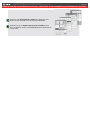
Service No : 000 102 04 2536
Date: xx-xx
INTERFACE MODULE
Made in Canada
PATENTS PENDING US: 2007-228827-A1
www.fortinbypass.com
HARDWARE VERSION
FIRMWARE VERSION
Module label | Étiquette sur le module
Notice: Updated Firmware and Installation Guides
Updated fi rmware and installation guides are posted on our web site on a regular
basis. We recommend that you update this module to the latest fi rmware and
download the latest installation guide(s) prior to the installation of this product.
Notice: Mise à jour microprogramme et Guides d’installations
Des mises à jour du Firmware (microprogramme) et des guides d’installation
sont mis en ligne régulièrement. Vérifi ez que vous avez bien la dernière version
logiciel et le dernier guide d’installation avant l’installation de ce produit.
WARNING
The information on this sheet is provided on an (as is) basis with no representation or warranty of accuracy whatsoever.
It is the sole responsibility of the installer to check and verify any circuit before connecting to it. Only a computer safe
logic probe or digital multimeter should be used. FORTIN ELECTRONIC SYSTEMS assumes absolutely no liability or
responsibility whatsoever pertaining to the accuracy or currency of the information supplied. The installation in every case
is the sole responsibility of the installer performing the work and FORTIN ELECTRONIC SYSTEMS assumes no liability
or responsibility whatsoever resulting from any type of installation, whether performed properly, improperly or any other
way. Neither the manufacturer or distributor of this module is responsible of damages of any kind indirectly or directly
caused by this module, except for the replacement of this module in case of manufacturing defects. This module must be
installed by qualifi ed technician. The information supplied is a guide only. This instruction guide may change without
notice. Visit www.fortinbypass.com to get the latest version.
MISE EN GARDE
L’information de ce guide est fournie sur la base de représentation (telle quelle) sans aucune garantie de précision et
d’exactitude. Il est de la seule responsabilité de l’installateur de vérifi er tous les fi ls et circuits avant d’effectuer les connexions.
Seuls une sonde logique ou un multimètre digital doivent être utilisés. FORTIN SYSTÈMES ÉLECTRONIQUES n’assume
aucune responsabilité de l’exactitude de l’information fournie. L’installation (dans chaque cas) est la responsabilité de
l’installateur effectuant le travail. FORTIN SYSTÈMES ÉLECTRONIQUES n’assume aucune responsabilité suite à
l’installation, que celle-ci soit bonne, mauvaise ou de n’importe autre type. Ni le manufacturier, ni le distributeur ne se
considèrent responsables des dommages causés ou ayant pu être causés, indirectement ou directement, par ce module,
excepté le remplacement de ce module en cas de défectuosité de fabrication. Ce module doit être installé par un technicien
qualifi é. L’information fournie dans ce guide est une suggestion. Ce guide d’instruction peut faire l’objet de changement
sans préavis. Consultez le www.fortinbypass.com pour voir la plus récente version.
Copyright © 2006-2018, FORTIN AUTO RADIO INC ALL RIGHTS RESERVED PATENT PENDING
TECH SUPPORT
Tél: 514-255-HELP (4357)
1-877-336-7797
ADDENDUM GUIDE WEB UPDATE | MISE À JOUR INTERNET
www.fortinbypass.com
ONE
Page 9 / 9
-
 1
1
-
 2
2
-
 3
3
-
 4
4
-
 5
5
-
 6
6
-
 7
7
-
 8
8
-
 9
9


dans d''autres langues
- English: Fortin 87751 Installation guide
Documents connexes
-
Fortin 79931 Manuel utilisateur
-
Fortin 80581 Manuel utilisateur
-
Fortin 80961 Guide d'installation
-
-
Fortin 79391 Guide d'installation
-
Fortin 80711 Guide d'installation
-
Fortin 998341 Guide d'installation
-
-
-