Peerless PLA60-UNL Guide d'installation
- Catégorie
- Supports muraux à panneau plat
- Taper
- Guide d'installation

ISSUED: 06-05-06 SHEET #: 202-9141-13 (2014-03-14)
2300 White Oak Circle • Aurora, Il 60502 • (800) 865-2112 • Fax: (800) 359-6500 • www.peerless-av.com
Max UL Load Capacity:
175 lb (79 kg)
Installation and Assembly:
Universal Articulating Swivel Arm for 37" - 95" Flat Panel
Displays
Models: PLA60-UNL, PLA60-UNLP-S, PLA60-UNLP, PLAV60-UNL-S, PLAV60-UNL,
PLAV60-UNLP-S, PLAV60-UNLP, PLA60-UNLP-GS, PLA60-UNLP-GB,
PLAV60-UNLP-GB

2 of 41 ISSUED: 06-05-06 SHEET #: 202-9141-13 (2014-03-14)
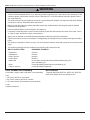
Tools Needed for Assembly
• stud fi nder ("edge to edge" stud fi nder is recommended)
• drill
• 3/16" (5mm) drill bit for wood studs
• 3/8" (10mm) masonry drill bit for concrete
• 7/16" socket wrench with extension (recommended)
• level
• phillips screwdriver
Accessories
• External Wall Plate (WSP716, WSP716-S, WSP724,
WSP724-S) (Metal Stud not evaluated by UL)
Note: Read entire instruction sheet before you start installation and assembly.
• Do not begin to install your Peerless product until you have read and understood the instructions and warnings
contained in this Installation Sheet. If you have any questions regarding any of the instructions or warnings, for US
customers please call Peerless customer care at 1-800-865-2112, for all international customers, please contact
your local distributor.
• This product should only be installed by someone of good mechanical aptitude, has experience with basic building
construction, and fully understands these instructions.
• Make sure that the supporting surface will safely support the combined load of the equipment and all attached
hardware and components.
• Never exceed the Maximum Load Capacity. See page one.
• If mounting to wood wall studs, make sure that mounting screws are anchored into the center of the studs. Use of
an "edge to edge" stud fi nder is highly recommended.
• Always use an assistant or mechanical lifting equipment to safely lift and position equipment.
• Tighten screws fi rmly, but do not overtighten. Overtightening can damage the items, greatly reducing their holding
power.
• This product is intended for indoor use only. Use of this product outdoors could lead to product failure and personal
injury.
• This product was designed to be installed on the following wall construction only;
WALL CONSTRUCTION HARDWARE REQUIRED
• Wood Stud Included
• Wood Beam Included
• Solid Concrete Included
• Cinder Block Included
• Metal Stud Do not attach except with Peerless Metal Stud Accessory Kit
(not evaluated by UL)
• Brick Contact Qualifi ed Professional (not evaluated by UL)
• Other or unsure? Contact Qualifi ed Professional
WARNING

3 of 41 ISSUED: 06-05-06 SHEET #: 202-9141-13 (2014-03-14)
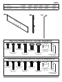
T
I
EFD
K
H
L
G
JMN RQO
V
W
P
SU
C
AB
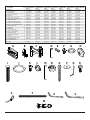
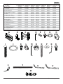
Parts List PLA60-UNLP-GB
Part # PLA60-UNLP-GS
Part #
PLA60-UNL
PLA60-UNLP
Part # PLA60-UNLP-S
Part #
PLAV60-UNL
PLAV60-UNLP
Part #
PLAV60-UNL-S
PLAV60-UNLP-S
Part # PLAV60-UNLP-GB
Part #
Description Qty
Awall plate 1 201-P1040 201-C4040 201-1040 201-4040 201-1040 201-1040 201-1040
Btilt-roll assembly 1 201-P1093 201-C4093 201-1093 201-4093 201-1048 201-1048 201-1048
Carm assembly 1 201-P1072 201-C4072 201-1072 201-4072 201-1049 201-1049 201-1049
Dwall support arm axle 1 201-1041 201-1041 201-1041 201-1041 201-1041 201-1041 201-1041
Evinyl trim 3 600-1012 600-1012 600-1012 600-1012 600-1012 600-1012 600-1012
FM10 x 15 mm screw bolt 8 520-9262 520-9262 520-9262 520-9262 520-9262 520-9262 520-9262
G.505 x .75 x .062" nylon washer 1 540-1074 540-1074 540-1074 540-1074 540-1074 540-1074 540-1074
Htilt adjustment knob 1 560-0108 560-0108 560-0108 560-0108 560-0108 560-0108 560-0108
Icarriage bolt 3/8"-16 x 3.25" 1 520-1315 520-1315 520-1315 520-1315 520-1315 520-1315 520-1315
J1.525 x 2 x .062" delrin washer 2 540-1070 540-1070 540-1070 540-1070 540-1070 540-1070 540-1070
K#8-32 x .375" socket head screw 1 520-1210 520-1210 520-1210 520-1210 520-1210 520-1210 520-1210
Lplastic fi nishing cap 8 590-1123 590-1123 590-1123 590-1123 590-1123 590-1123 590-1123
Mholding pin 1 580-1166 580-1166 580-1166 580-1166 580-1166 580-1166 580-1166
Nretainer plug 1 590-1007 590-1007 590-1007 590-1007 590-1007 590-1007 590-1007
O5/16 x 3" wood screw 8 520-1243 520-1243 520-1243 520-1243 520-1243 520-1243 520-1243
P.250 x 1 x .068" washer 8 540-1063 540-1063 540-1063 540-1063 540-1063 540-1063 540-1063
Q9/64" allen wrench 1 560-9728 560-9728 560-9728 560-9728 560-9728 560-9728 560-9728
Rcable management clips 4 590-1166 590-1166 590-1166 590-1166 590-1166 590-1166 590-1166
Scable tie 4 590-1168 590-1168 590-1168 590-1168 590-1168 590-1168 590-1168
T36" polyester mesh sleeve 1 600-1015 600-1015 600-1015 600-1015 600-1015 600-1015 600-1015
U6 mm allen wrench 1 560-9716 560-9716 560-9716 560-9716 560-9716 560-9716 560-9716
V10 mm allen wrench 1 - - - - 560-9727 560-9727 560-9727
Wanchor 8 590-0321 590-0321 590-0321 590-0321 590-0321 590-0321 590-0321

4 of 41 ISSUED: 06-05-06 SHEET #: 202-9141-13 (2014-03-14)
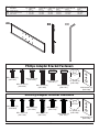
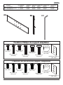
Phillips Adapter Bracket Fasteners
M5 x 12 mm (4)
(520-1027)
M5 x 25 mm (4)
(520-9543)
M6 x 12 mm (4)
(520-1128)
M6 x 25 mm (4)
(520-1208)
.75" spacer (4)
(540-1059)
Multi-washer (4)
(580-1398)
M8 x 25 mm (4)
(520-1031)
M8 x 12 mm (4)
(520-9571)
M5 x 25mm (4)
(520-1122)
M5 x 12mm (4)
(520-1064) M6 x 12mm (4)
(520-1050)
M6 x 25mm (4)
(520-1211) M8 x 25mm (4)
(520-1101)
M8 x 12mm (4)
(520-1724) .75" spacer (4)
(540-1059)
Multi-washer (4)
(580-1398)
Security Adapter Bracket Fasteners
CC
BB
AA
Parts List PLA60-UNL
PLAV60-UNL
Part # PLAV60-UNL-S
Part #
PLA60-UNLP
PLAV60-UNLP
Part #
PLA60-UNLP-S
PLAV60-UNLP-S
Part #
PLA60-UNLP-GB
PLAV60-UNLP-GB
Part # PLA60-UNLP-GS
Part #
Description Qty
AA adapter bracket 1 201-1110 201-4110 201-1110 201-4110 201-P1110 201-C4110
BB shallow adapter bracket 2 202-1655 202-4655 202-1656 202-4656 202-P1656 202-C4656
CC allen wrench 1 560-9646 560-9646 560-9646 560-9646 560-9646 560-9646

5 of 41 ISSUED: 06-05-06 SHEET #: 202-9141-13 (2014-03-14)
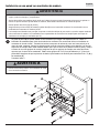
A
O
P
1
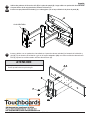
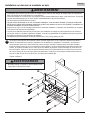
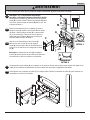
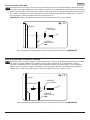
Installation to Wood Stud Wall
Wall plate (A) can be mounted to two studs that are 16" apart. Use a stud fi nder to locate the edges of the studs.
Use of an edge-to-edge stud fi nder is highly recommended. Based on their edges, draw a vertical line down each
stud’s center. Place wall plate on wall as a template. The top mounting slots should be located at your desired
display center. Level plate, and mark the center of the eight mounting holes. Make sure that the mounting holes
are on the stud centerlines. Drill eight 3/16" (5mm) dia. holes 3" (76mm) deep. Make sure that the wall plate is
level, secure it using eight 5/16 x 3" wood screws (O) and washers (P).
Skip to step 2
• Never mount this product to metal studs without the
required accessory.
WARNING
• Installer must verify that the supporting surface will safely support the combined load of the equipment and all
attached hardware and components.
• Tighten wood screws so that wall plate is fi rmly attached, but do not overtighten. Overtightening can damage the
screws, greatly reducing their holding power.
• Never tighten in excess of 80 in. • lb (9 N.M.).
• Make sure that mounting screws are anchored into the center of the stud. The use of an "edge to edge" stud fi nder
is highly recommended.
• Hardware provided is for attachment of mount through standard thickness drywall or plaster into wood studs. Install-
ers are responsible to provide hardware for other types of mounting situations (not evaluated by UL).
WARNING

6 of 41 ISSUED: 06-05-06 SHEET #: 202-9141-13 (2014-03-14)
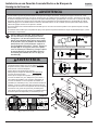
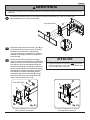
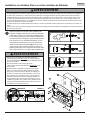
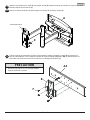
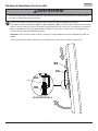
Use wall plate (A), making sure that it is level, as
a template to mark holes. The top mounting slots
should be located at your desired display center.
Use the masonry bit to drill 3/8" (10mm) dia. holes
to a minimum depth of 3" (76mm). Insert anchors
(W) in holes fl ush with wall as shown (right). Place
wall plate (A) over anchors (W) and secure with
5/16 x 3" wood screws (O) and washers (P).
1
Installation to Solid Concrete or Cinder Block Wall
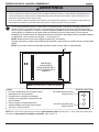
CUTAWAY VIEW
INCORRECT CORRECT
wall
plate
wall
plate
plaster/
dry wall
plaster/
dry wall
concrete concrete
1
3
2
W
Drill holes and insert anchors (W).
Place plate (A) over anchors (W) and secure with screws (O).
Tighten all fasteners.
A
W
O
concrete
surface
• When installing Peerless wall mounts on cinder block, verify that you have a minimum of 1-3/8" (35mm) of actual
concrete thickness in the hole to be used for the concrete anchors. Do not drill into mortar joints! Be sure to mount
in a solid part of the block, generally 1" (25mm) minimum from the side of the block. Cinder block must meet ASTM
C-90 specifi cations. It is suggested that a standard electric drill on slow setting is used to drill the hole instead of a
hammer drill to avoid breaking out the back of the hole when entering a void or cavity.
• Concrete must be 2000 psi density minimum. Lighter density concrete may not hold concrete anchor.
• Make sure that the supporting surface will safely support the combined load of the equipment and all attached
hardware and components.
WARNING
• Tighten screws so that wall plate is fi rmly attached,
but do not overtighten. Overtightening can damage
screws, greatly reducing their holding power.
• Never tighten in excess of 80 in. • lb (9 N.M.).
• Always attach concrete expansion anchors directly
to load-bearing concrete.
• Never attach concrete expansion anchors to
concrete covered with plaster, drywall, or other
fi nishing material. If mounting to concrete surfaces
covered with a fi nishing surface is unavoidable (not
evaluated by UL), the fi nishing surface must be
counterbored as shown below. Be sure concrete
anchors do not pull away from concrete when
tightening screws. If plaster/drywall is thicker than
5/8" (16mm), custom fasteners must be supplied by
installer (not evaluated by UL).
WARNING
A
O
P
W

7 of 41 ISSUED: 06-05-06 SHEET #: 202-9141-13 (2014-03-14)
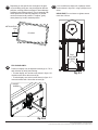
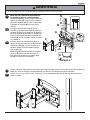
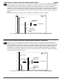
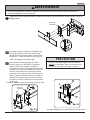
Snap four cable management clips (R) into top or bottom of arm assembly (C) as shown. Cable ties (S) are used
with clips for cord management.
Slide one mesh sleeve (T) over each cable. Use cable ties (S) to tighten mesh sleeves to cables.
R
C
3
T
3-1
KD
N
J
D
M
J
C
DETAIL 3
A
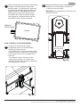
Note: There are fi ve mounting positions. The
center position is shown (right). Slide washer
(J) over wall support arm axle (D). Next, insert
plastic cap (N) into axle. Then, insert holding pin
(M) into axle. See detail 1.
Place arm assembly (C) with washer (J) into wall
plate (A). Insert axle assembly shown in detail
1 through wall plate (A), arm assembly (C), and
washer (J). Lock axle in place by aligning hold-
ing pin (M) with notches shown in detail 2.
Insert socket cap screw (K) into hole at bottom
of wall support arm axle (D) as shown in detail 3.
Tighten screw using 9/64" allen wrench (Q).
Note: Fit of axle (D) into wall plate (A) and arm
assembly (C) will be tight. Gently tap into place
with a hammer if necessary.
2
2-1
2-2
DETAIL 1
DETAIL 2
• If you are uncertain that product is properly installed, call customer care.
WARNING
S
NOTCH

8 of 41 ISSUED: 06-05-06 SHEET #: 202-9141-13 (2014-03-14)
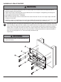
Attach two pieces of vinyl trim (E) to wall plate (A). Next, attach one piece of vinyl trim to bottom of swivel box on
arm assembly (C).
Insert one fi nishing cap (L) into each unused hole of wall plate (A).
B
I
F
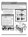
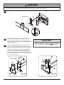
Insert and tape carriage bolt (I) into top hole of pitch-roll assembly (B). Attach tilt-roll assembly to adapter bracket
(AA) with four M10 socket screws (F). Tighten screws using 6mm allen wrench (U).
• Do not overtighten screws! Overtightening may
hinder roll option.
CAUTION
4
5
4-1
LA
E
SWIVEL BOX
C
AA

9 of 41 ISSUED: 06-05-06 SHEET #: 202-9141-13 (2014-03-14)
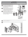
Hook tilt-roll assembly (B) onto M10 screws (F).
Insert carriage bolt (I) into slot of swivel box as
shown in fi gure 6.1. Install nylon washer (G) and tilt
adjustment knob (H).
Install remaining two M10 screws (F) as shown in
fi gure 6.2. HAND TIGHTEN all four M10 screws to
allow for tilt adjustment. Remove tape from carriage
bolt (I). For tilt adjustment, push back on the top of
plasma to relieve pressure on knob. Adjust tilt to
desired position and tighten tilt adjustment knob (H),
then securely tighten all four M10 screws (F) using
6mm allen wrench (U).
Insert two M10 screws (F) into swivel box on arm assembly (C) as shown. Leave approx. .25" of exposed thread.
.25" F
• Use an assistant or mechanical lifting equipment to safely lift and position the plasma TV.
WARNING
• After tilt is adjusted, all fasteners must be tightened.
Failure to do so will result in damage to the mount.
CAUTION
6
6-1
6-2
fi g. 6.1 fi g. 6.2
SWIVEL BOX
SWIVEL BOX
I
BF
H
GH
F
I
C
Adapter bracket not shown for clarity. Adapter bracket not shown for clarity.

10 of 41 ISSUED: 06-05-06 SHEET #: 202-9141-13 (2014-03-14)
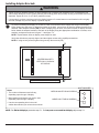
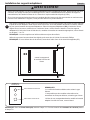
Note: "X" dimensions should be equal.
Installing Adapter Brackets
To prevent scratching the display, set a cloth on a fl at, level surface that will support the weight of the display.
Place display face side down. If display has knobs on the back, remove them to allow the adapter brackets to be
attached. Place adapter brackets (BB) on back of display, align to holes, and center on back of display as shown
below. Attach the adapter brackets to the back of the display using the appropriate combination of screws, multi-
washers, and spacers as shown in fi gure 7.1 and fi gure 7.2.
NOTE: Top and bottom holes on display must always be used.
Verify that all holes are properly aligned, and then tighten screws using a phillips screwdriver.
NOTE: If using security screws, tighten using security allen wrench (CC).
BB CENTER BRACKETS
VERTICALLY ON BACK
OF DISPLAY
X
X
Notes:
• The number of fasteners used will vary,
depending upon the type of display.
• Multi-washers and spacers may not be used,
depending upon the type of display.
• Use the corresponding hole in the multi-
washer that matches your screw size as shown.
MEDIUM HOLE FOR M5 SCREWS
LARGE HOLE FOR M6 SCREWS
MULTI-WASHER
7
• Tighten screws so adapter brackets are fi rmly attached. Do not tighten with excessive force. Overtightening can
cause stress damage to screws, greatly reducing their holding power and possibly causing screw heads to become
detached. Tighten to 40 in. • lb (4.5 N.M.) maximum torque.
• If screws don't get three complete turns in the display inserts or if screws bottom out and bracket is still not tightly
secured, damage may occur to display or product may fail.
WARNING
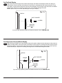
NOTE: For fl at back displays proceed to step 7-1. For bump-out or recessed back display skip to step 7-2

11 of 41 ISSUED: 06-05-06 SHEET #: 202-9141-13 (2014-03-14)
Begin with the shortest length screw, hand thread through multi-washer and adapter bracket into display as
shown below. Screw must make at least three full turns into the mounting hole and fi t snug into place. Do not
over tighten. If screw cannot make three full turns into the display, select a longer length screw from the baffl ed
fastener pack. Repeat for remaining mounting holes, level brackets and tighten screws.
NOTE: Spacers may not be used, depending upon the type of display.
Begin with longer length screw, hand thread through multi-washer, adapter bracket and spacer in that order into
display as shown below. Screw must make at least three full turns into the mounting hole and fi t snug into place.
Do not over tighten. If screw cannot make three full turns into the display, select a longer length screw from the
baffl ed fastener pack. Repeat for remaining mounting holes, level brackets and tighten screws.
For Flat Back Display
For Bump-out or Recessed Back Display
7-1
7-2
If you have any questions, please call Peerless customer care at 1-800-865-2112.
If you have any questions, please call Peerless customer care at 1-800-865-2112.
DISPLAY
MULTI-WASHER
SCREW
ADAPTER
BRACKET
(BB)
fi g. 7.2
SPACER
fi g. 7.1
ADAPTER
BRACKET
(BB)
DISPLAY
MULTI-WASHER
SCREW

12 of 41 ISSUED: 06-05-06 SHEET #: 202-9141-13 (2014-03-14)
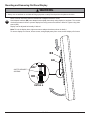
Mounting and Removing Flat Panel Display
Refer to mount instruction sheet for attachment of adapter bracket to mount.
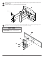
Hook adapter brackets (BB) onto adapter bracket (AA), then slowly swing display in as shown. Turn screws
clockwise at least six times to prevent display from being removed as shown in detail 4. Tighten using allen
wrench (CC).
Display can be adjusted horizontally if desired.
Note: To lock the display down, tighten screws to adapter bracket as shown in detail 4.
To remove display from mount, loosen screws, swing display away from mount, and lift display off of mount.
8
• Always use an assistant or mechanical lifting equipment to safely lift and position the plasma television.
WARNING
AA
BB
DETAIL 4
SAFETY/SECURITY
SCREWS
AA
BB

13 of 41 ISSUED: 06-05-06 SHEET #: 202-9141-13 (2014-03-14)
FOR PLAV60 ONLY:
Position of display may be adjusted vertically up to .79" in
each direction by doing the following:
• To lower display, turn socket screw shown in fi gure 10.1
clockwise with 10mm allen wrench (V).
• To raise display, turn socket screw shown in fi gure 10.1
counterclockwise with 10mm allen wrench (V).
If it is too diffi cult to adjust roll of plasma, loosen
screws shown in fi gure 9.1 using a phillips screw-
driver.
IMPORTANT! Do not loosen or tighten screws
more than 1/8 turn.
Depending on the specifi c size & weight of the plas-
ma, articulating swing arm may be angled at different
positions, causing plasma to appear to lean sideways
at different articulating positions. Tilt-roll assembly (B)
allows plasma to be manually adjusted, so plasma
can be horizontal at all positions. To adjust, gently
rotate plasma by hand to desired position.
99-1
10
SOCKET
SCREW
fi g. 10.1
fi g. 9.1
ROLL
ADJUSTMENT
SCREWS
ARTICULATING
ARM
PLASMA
© 2014, Peerless Industries, Inc. All rights reserved.
All other brand and product names are trademarks or registered trademarks of their respective owners.

PUBLICADO: 06-05-06 HOJA #:202-9141-13 (2014-03-
2300 White Oak Circle • Aurora, Il 60502 • (800) 865-2112 • Fax: (800) 359-6500 • www.peerless-av.com
Capacidad de carga máxima de UL:
175 lb (79 kg)
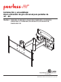
Instalación y ensamblaje:
Brazo articulador de giro universal para pantallas de
37" - 95"
Modelos: PLA60-UNL, PLA60-UNLP-S, PLA60-UNLP, PLAV60-UNL-S, PLAV60-UNL,
PLAV60-UNLP-S, PLAV60-UNLP, PLA60-UNLP-GS, PLA60-UNLP-GB,
PLAV60-UNLP-GB

Español
15 de 41 PUBLICADO: 06-05-06 HOJA #:202-9141-13 (2014-03-14)
Herramientas necesarias para el ensamblaje
• localizador de montantes (se recomienda uno de “borde a borde”)
• taladro
• broca de 3/16" (5mm) para montantes de madera
• broca de 3/8" (10mm) para taladro de albaρilerνa para concreto
• llave de copa 7/16" con extensión (se recomienda)
• nivel
• destornillador phillips
Accesorios
• Placa de pared externa (WSP716, WSP716-S,
WSP724, WSP724-S)
(Montante de metal no evaluado por UL).
Nota: Lea la hoja de instrucciones completa antes de comenzar la instalación y el ensamblaje.
Tabla de contenido
Lista de piezas............................................................................................................................................................... 16, 17
Instalación en una pared con montantes de madera dobles ............................................................................................... 18
Instalación en una pared de concreto macizo o de bloques de hormigón de escorias ....................................................... 19
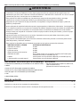
• No comience a instalar su producto de Peerless hasta haber leído y entendido las instrucciones y las advertencias
contenidas en la Hoja de Instalación. Si tiene alguna pregunta acerca de cualquiera de las instrucciones o las
advertencias, por favor, llame a Servicio al Cliente de Peerless al 1-800-865-2112 si está en EE. UU. Si es un cliente
internacional, por favor, comuníquese con su distribuidor local.
• Este producto sólo debe ser instalado por una persona que tenga una buena aptitud mecánica, que tenga
experiencia en construcción básica de edifi cios y que entienda estas instrucciones en su totalidad.
• Asegúrese de que la superfi cie de apoyo sostendrá, con seguridad, la carga combinada del equipo y todos los
fi jadores y componentes.
• Nunca sobrepase la capacidad máxima de soportar carga aceptada por Underwriters Laboratories. Vea la página 14.
• Si va a instalar el producto en una pared con montantes de madera, asegúrese de que los tornillos de montaje estén
anclados en el centro de los montantes. Se recomienda utilizar un localizador de montantes de "borde a borde".
• Siempre cuente con la ayuda de un asistente o utilice un equipo mecánico de izar para levantar y colocar el equipo
con más seguridad.
• Apriete los tornillos con fi rmeza, pero no en exceso. Apretarlos en exceso puede dañar los artículos y puede
disminuir signifi cativamente su fuerza de fi jación.
• Este producto está diseñado para uso en interiores solamente. Utilizar este producto en exteriores podría causar
fallas del producto y lesiones a individuos.
• Este producto fue diseñado para ser instalado en paredes con la siguiente construcción solamente:
CONSTRUCCIÓN DE LA PARED ACCESORIOS NECESARIOS
• Montante de madera Incluido
• Viga de madera Incluido
• Concreto macizo Incluido
• Bloque de hormigón de escorias Incluido
• Montante de metal No lo instale excepto con el juego de accesorios de Peerless para
montantes de metal (no evaluados por UL)
• Ladrillo Comuníquese con un profesional califi cado (no evaluados por UL)
• ¿Otra superfi cie o no está seguro? Comuníquese con un profesional califi cado
ADVERTENCIA

Español
16 de 41 PUBLICADO: 06-05-06 HOJA #:202-9141-13 (2014-03-14)
T
I
E FD
K
H
L
G
JMN RQO
V
W
P
SU
C
AB
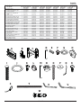
Lista de piezas PLA60-UNLP-GB
Nº de pieza PLA60-UNLP-GS
Nº de pieza
PLA60-UNL
PLA60-UNLP
Nº de pieza PLA60-UNLP-S
Nº de pieza
PLAV60-UNL
PLAV60-UNLP
Nº de pieza
PLAV60-UNL-S
PLAV60-UNLP-S
Nº de pieza PLAV60-UNLP-GB
Nº de pieza
Descripción Cant.
Aplaca de pared 1 201-P1040 201-C4040 201-1040 201-4040 201-1040 201-1040 201-1040
Barmazón de inclinación y giro 1 201-P1093 201-C4093 201-1093 201-4093 201-1048 201-1048 201-1048
Carmazón del brazo 1 201-P1072 201-C4072 201-1072 201-4072 201-1049 201-1049 201-1049
Deje del brazo de soporte de
pared
1 201-1041 201-1041 201-1041 201-1041 201-1041 201-1041 201-1041
Eribete de vinilo 3 600-1012 600-1012 600-1012 600-1012 600-1012 600-1012 600-1012
Ftornillo de rosca M10 x 15 mm 8 520-9262 520-9262 520-9262 520-9262 520-9262 520-9262 520-9262
Garandela de nilón .505 x .062" 1 540-1074 540-1074 540-1074 540-1074 540-1074 540-1074 540-1074
Hperilla ajuste de la inclinación 1 560-0108 560-0108 560-0108 560-0108 560-0108 560-0108 560-0108
Iperno cabeza 3/8"-16 x 3.25" 1 520-1315 520-1315 520-1315 520-1315 520-1315 520-1315 520-1315
Jarandela delrin de 1.525 x .062" 2 540-1070 540-1070 540-1070 540-1070 540-1070 540-1070 540-1070
Ktornillo hueca 8 x -32 x 0.375" 1 520-1210 520-1210 520-1210 520-1210 520-1210 520-1210 520-1210
Lcubierta plástica de acabado 8 590-1123 590-1123 590-1123 590-1123 590-1123 590-1123 590-1123
Mpasador de sujeción 1 580-1166 580-1166 580-1166 580-1166 580-1166 580-1166 580-1166
Ntapón retenedor 1 590-1007 590-1007 590-1007 590-1007 590-1007 590-1007 590-1007
Otornillo de madera 5/16 x 3" 8 520-1243 520-1243 520-1243 520-1243 520-1243 520-1243 520-1243
Parandela de 250 x 1 x .068" 8 540-1063 540-1063 540-1063 540-1063 540-1063 540-1063 540-1063
Qllave allen de 9/64 1 560-9728 560-9728 560-9728 560-9728 560-9728 560-9728 560-9728
Rclips de sujeción de cables 4 590-1166 590-1166 590-1166 590-1166 590-1166 590-1166 590-1166
Ssujetacables 4 590-1168 590-1168 590-1168 590-1168 590-1168 590-1168 590-1168
Tfunda de malla de poliéster 36" 1 600-1015 600-1015 600-1015 600-1015 600-1015 600-1015 600-1015
Ullave allen de 6 mm 1 560-9716 560-9716 560-9716 560-9716 560-9716 560-9716 560-9716
Vllave allen de 10 mm 1 - - - - 560-9727 560-9727 560-9727
Wanclaje para concreto 8 590-0321 590-0321 590-0321 590-0321 590-0321 590-0321 590-0321

Español
17 de 41 PUBLICADO: 06-05-06 HOJA #:202-9141-13 (2014-03-14)
M5 x 25mm (4)
(520-1122)
M5 x 12mm (4)
(520-1064) M6 x 12mm (4)
(520-1050)
M6 x 25mm (4)
(520-1211) M8 x 25mm (4)
(520-1101)
M8 x 12mm (4)
(520-1724)
Fijaciones de seguridad para los soportes adaptadores
M5 x 12 mm (4)
(520-1027)
M5 x 25 mm (4)
(520-9543)
M6 x 12 mm (4)
(520-1128)
M6 x 25 mm (4)
(520-1208)
.75" espaciador (4)
(540-1059)
M8 x 25 mm (4)
(520-1031)
M8 x 12 mm (4)
(520-9571)
Fijaciones Phillips para los soportes adaptadores
arandela múltiple (4)
(580-1398)
.75" espaciador (4)
(540-1059)
arandela múltiple (4)
(580-1398)
CC
BB
AA
Lista de piezas PLA60-UNL
PLAV60-UNL
Nº de pieza PLAV60-UNL-S
Nº de pieza
PLA60-UNLP
PLAV60-UNLP
Nº de pieza
PLA60-UNLP-S
PLAV60-UNLP-S
Nº de pieza
PLA60-UNLP-GB
PLAV60-UNLP-GB
Nº de pieza PLA60-UNLP-GS
Nº de pieza
Descripción Cant.
AA soporte adaptador 1 201-1110 201-4110 201-1110 201-4110 201-P1110 201-C4110
BB soporte adaptador de poca profundidad 2 202-1655 202-4655 202-1656 202-4656 202-P1656 202-C4656
CC llave allen 4mm 1 560-9646 560-9646 560-9646 560-9646 560-9646 560-9646

Español
18 de 41 PUBLICADO: 06-05-06 HOJA #:202-9141-13 (2014-03-14)
A
O
P
La placa de pared (A) se puede instalar en dos montantes que tengan una separaciσn de 16". Utilice un
localizador de montantes para ubicar los bordes de los montantes. Se recomienda utilizar un localizador de
montantes de “borde a borde”. Tomando los bordes como punto de referencia, trace una lνnea vertical por el
centro de cada montante. Coloque la placa de pared contra la pared para utilizarla como plantilla. Las ranuras
superiores de montaje deben estar ubicadas donde quiere que el centro de la pantalla. Nivele la placa y marque
el centro de los ocho agujeros de montaje. Asegϊrese de que los agujeros de montaje estιn sobre las lνneas
que trazσ por el centro de los montantes. Taladre ocho agujeros de 3/16" (5mm) de diámetro y 3" (76mm) de
profundidad. Asegϊrese de que la placa estι nivelada, fνjela usando ocho tornillos para madera de 5/16 x 3" (O) y
las arandelas (P).
Proceda al paso 2
1
Instalación en una pared con montantes de madera
• El instalador debe verifi car que la superfi cie de apoyo sea capaz de soportar fi rmemente la carga combinada del
equipo y todos los herrajes y componentes.
• Apriete los tornillos para madera de tal modo que la placa de apoyo quede fi rmemente sujeta, pero no apriete en
exceso. El apriete excesivo puede dañar los tornillos, reduciendo enormemente su fuerza de fi jación.
• Nunca apriete más de 80 pulg-lb (9 N•m).
• Asegúrese de que los tornillos de montaje queden bien fi jos en el centro del montante. Se recomienda usar un
localizador de montantes de "borde a borde".
• Los herrajes suministrados son para fi jar el soporte a través de tabique de yeso-cartón o yeso de espesor estándar
a los montantes de madera. Los instaladores son responsables de suministrar los herrajes para otros tipos de
situaciones de montaje (no evaluados por UL).
ADVERTENCIA
• Nunca instale este producto con montantes de metal
sin el accesorio necesario.
ADVERTENCIA

Español
19 de 41 PUBLICADO: 06-05-06 HOJA #:202-9141-13 (2014-03-14)
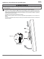
Utilice la placa de pared (A), asegurándose de
que esté nivelada, como plantilla para marcar
los agujeros. Las ranuras superiores de montaje
deben estar ubicadas donde quiere que el centro
de la pantalla. Utilice el pedacito de la albañilería
para perforar 3/8" (10mm) diámetro. agujeros a
una profundidad mínima de 3" (76mm). Inserte los
anclajes (W) en los agujeros a ras con la pared,
como se muestra (a la derecha). Coloque la placa
de pared (A) sobre los anclajes (W) y fi jela con
los tornillos para madera de 5/16 x 3" (O) y las
arandelas (P).
1
• Cuando instale soportes de pared Peerless en bloques de hormigón de escorias, verifi que que tengan un mínimo de 1-3/8"
(35mm) de superfi cie efectiva de concreto en el agujero que va a utilizar para los anclajes de concreto. ¡No perfore en las juntas
de mortero! Asegúrese de instalar el soporte en una parte sólida del bloque, generalmente a un mínimo de 1" (25mm) del costado
del bloque. El bloque de hormigón de escorias debe ser de conformidad con las especifi caciones C-90 de ASTM. Se sugiere
taladrar el agujero con un taladro eléctrico normal en velocidad lenta en vez de un taladro percutor para evitar romper la parte
trasera del agujero al entrar en un espacio o cavidad.
• El concreto debe tener una densidad mínima de 2000 psi. Un concreto menos denso podría no ser capaz de sujetar el anclaje
para concreto.
• El instalador debe verifi car que la superfi cie de apoyo sea capaz de soportar fi rmemente la carga combinada del equipo y todos
los herrajes y componentes.
ADVERTENCIA
• Apriete los tornillos de tal modo que la placa de apoyo
quede fi rmemente sujeta, pero no los apriete en exceso.
El apriete excesivo puede dañar los tornillos, reduciendo
enormemente su fuerza de fi jación.
• Nunca apriete más de 80 pulg-lb (9 N•m).
• Siempre fi je los anclajes de expansión directamente al
concreto que soporta carga.
• Nunca fi je los anclajes de expansión a una pared de
concreto recubierta con yeso, tabiques de yeso-cartón u
otro material de acabado. Si el montaje a superfi cies de
concreto recubiertas con una superfi cie de acabado es
inevitable (no evaluadas por UL), será necesario escariar el
acabado, como se muestra más abajo. Asegúrese de que
los anclajes de concreto no se alejen del concreto al apretar
los tornillos. Si el grosor de la pared de yeso/tabique de
yeso-cartón es mayor que 5/8" (16mm), el instalador deberá
suministrar fi jaciones especiales (no evaluadas por UL).
ADVERTENCIA
1
3
2
W
Perfore los agujeros y después inserte los anclajes (W).
Coloque la placa (A) sobre los anclajes (W) y fíjela con
los tornillos (O).
Apriete todas las fi jaciones.
A
W
O
superfi cie de
concreto
VISTA EN CORTE
INCORRECTO CORRECTO
concreto
placa
de
pared
placa
de
pared
concreto
yeso / tabique de yeso-cartón
A
O
P
W
Instalación en una Pared de Concreto Macizo o de Bloques de
Hormigón de Escorias

Español
20 de 41 PUBLICADO: 06-05-06 HOJA #:202-9141-13 (2014-03-14)
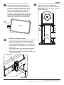
Inserte, a presión, cuatro clips de sujeción de cables (R) en la parte superior o en la parte inferior del armazón del
brazo (C), como se muestra. Los sujetacables (S) se usan con los clips para recoger los cordones.
Deslice una funda de malla (T) sobre cada cable. Use los sujetacables (S) para apretar la funda de malla que
cubre los cables.
3
3-1
Nota: Hay cinco posiciones de instalación.
Se muestra la posición central (derecha).
Deslice la arandela (J) sobre el eje del brazo del
soporte de pared (D). Luego inserte la cubierta
plástica de acabado (N) en el eje. Luego inserte
el pasador de sujeción (M) en el eje. Vea el
detalle 1.
Coloque el armazón del brazo (C) con la
arandela (J) en la placa de pared (A). Inserte el
armazón del eje que se muestra en el detalle 1 a
través de la placa de pared (A) y la arandela (J).
Fije el eje en su lugar alineando el pasador de
sujeción (M) con las muescas, que se muestran
en el detalle 2.
Inserte el tornillo de cabeza hueca (K) en el
agujero de la parte interior del eje del brazo del
soporte de pared (D), como se muestra en el
detalle 3. Apriete el tornillo usando una llave
allen de 9/64" (Q).
Nota: El eje (D) quedará apretado en la placa
de pared (A) y en el armazón del brazo (C).
Déle golpecitos suaves con un martillo para
llevarlo a su lugar, de ser necesario.
2
2-1
2-2
DETALLE 1
DETALLE 2
DETALLE 3
• Si no está seguro de que el producto esté bien instalado, llame a Servicio al Cliente.
ADVERTENCIA
R
C
T
S
KD
N
J
D
M
J
C
A
Muesca
La page est en cours de chargement...
La page est en cours de chargement...
La page est en cours de chargement...
La page est en cours de chargement...
La page est en cours de chargement...
La page est en cours de chargement...
La page est en cours de chargement...
La page est en cours de chargement...
La page est en cours de chargement...
La page est en cours de chargement...
La page est en cours de chargement...
La page est en cours de chargement...
La page est en cours de chargement...
La page est en cours de chargement...
La page est en cours de chargement...
La page est en cours de chargement...
La page est en cours de chargement...
La page est en cours de chargement...
La page est en cours de chargement...
La page est en cours de chargement...
La page est en cours de chargement...
-
 1
1
-
 2
2
-
 3
3
-
 4
4
-
 5
5
-
 6
6
-
 7
7
-
 8
8
-
 9
9
-
 10
10
-
 11
11
-
 12
12
-
 13
13
-
 14
14
-
 15
15
-
 16
16
-
 17
17
-
 18
18
-
 19
19
-
 20
20
-
 21
21
-
 22
22
-
 23
23
-
 24
24
-
 25
25
-
 26
26
-
 27
27
-
 28
28
-
 29
29
-
 30
30
-
 31
31
-
 32
32
-
 33
33
-
 34
34
-
 35
35
-
 36
36
-
 37
37
-
 38
38
-
 39
39
-
 40
40
-
 41
41


Peerless PLA60-UNL Guide d'installation
- Catégorie
- Supports muraux à panneau plat
- Taper
- Guide d'installation
dans d''autres langues
Documents connexes
-
Peerless PLAV60-UNL Manuel utilisateur
-
-
-
-
-
-
-
-
PEERLESS-AV DST975-4 Guide d'installation
-