Lincoln Electric Invertec V311-T AC/DC Manuel utilisateur
- Catégorie
- Système de soudage
- Taper
- Manuel utilisateur

INVERTEC V311-T AC/DC
®
OPERATORʼS MANUAL
IM10051
September, 2011
For use with machines having Code Numbers: 11685
• Sales and Service through Subsidiaries and Distributors Worldwide •
Cleveland, Ohio 44117-1199 U.S.A. TEL: 216.481.8100 FAX: 216.486.1751 WEB SITE: www.lincolnelectric.com
• World's Leader in Welding and Cutting Products •
Copyright © Lincoln Global Inc.
Safety Depends on You
Lincoln arc welding and cutting
equipment is designed and built
with safety in mind. However,
your overall safety can be
increased by proper installation ...
and thoughtful operation on your
part. DO NOT INSTALL, OPER-
ATE OR REPAIR THIS EQUIP-
MENT WITHOUT READING
THIS MANUAL AND THE
SAFETY PRECAUTIONS CON-
TAINED THROUGHOUT. And,
most importantly, think before you
act and be careful.
This manual covers equipment which is no
longer in production by The Lincoln Electric Co.
Specications and availability of optional
features may have changed.

FOR ENGINE
powered equipment.
1.a. Turn the engine off before troubleshooting and maintenance
work unless the maintenance work requires it to be running.
____________________________________________________
1.b. Operate engines in open, well-ventilated
areas or vent the engine exhaust fumes
outdoors.
____________________________________________________
1.c. Do not add the fuel near an open flame
welding arc or when the engine is running.
Stop the engine and allow it to cool before
refueling to prevent spilled fuel from vaporiz-
ing on contact with hot engine parts and
igniting. Do not spill fuel when filling tank. If
fuel is spilled, wipe it up and do not start
engine until fumes have been eliminated.
____________________________________________________
1.d. Keep all equipment safety guards, covers and devices in
position and in good repair.Keep hands, hair, clothing and
tools away from V-belts, gears, fans and all other moving
parts when starting, operating or repairing equipment.
____________________________________________________
1.e. In some cases it may be necessary to remove safety
guards to perform required maintenance. Remove
guards only when necessary and replace them when the
maintenance requiring their removal is complete.
Always use the greatest care when working near moving
parts.
___________________________________________________
1.f. Do not put your hands near the engine fan.
Do not attempt to override the governor or
idler by pushing on the throttle control rods
while the engine is running.
___________________________________________________
1.g. To prevent accidentally starting gasoline engines while
turning the engine or welding generator during maintenance
work, disconnect the spark plug wires, distributor cap or
magneto wire as appropriate.
i
SAFETY
i
ARC WELDING CAN BE HAZARDOUS. PROTECT YOURSELF AND OTHERS FROM POSSIBLE SERIOUS INJURY OR DEATH.
KEEP CHILDREN AWAY. PACEMAKER WEARERS SHOULD CONSULT WITH THEIR DOCTOR BEFORE OPERATING.
Read and understand the following safety highlights. For additional safety information, it is strongly recommended that you
purchase a copy of “Safety in Welding & Cutting - ANSI Standard Z49.1” from the American Welding Society, P.O. Box
351040, Miami, Florida 33135 or CSA Standard W117.2-1974. A Free copy of “Arc Welding Safety” booklet E205 is available
from the Lincoln Electric Company, 22801 St. Clair Avenue, Cleveland, Ohio 44117-1199.
BE SURE THAT ALL INSTALLATION, OPERATION, MAINTENANCE AND REPAIR PROCEDURES ARE
PERFORMED ONLY BY QUALIFIED INDIVIDUALS.
WARNING
ELECTRIC AND
MAGNETIC FIELDS
may be dangerous
2.a. Electric current flowing through any conductor causes
localized Electric and Magnetic Fields (EMF). Welding
current creates EMF fields around welding cables and
welding machines
2.b. EMF fields may interfere with some pacemakers, and
welders having a pacemaker should consult their physician
before welding.
2.c. Exposure to EMF fields in welding may have other health
effects which are now not known.
2.d. All welders should use the following procedures in order to
minimize exposure to EMF fields from the welding circuit:
2.d.1.
Route the electrode and work cables together - Secure
them with tape when possible.
2.d.2. Never coil the electrode lead around your body.
2.d.3. Do not place your body between the electrode and
work cables. If the electrode cable is on your right
side, the work cable should also be on your right side.
2.d.4. Connect the work cable to the workpiece as close as
possible to the area being welded.
2.d.5. Do not work next to welding power source.
1.h. To avoid scalding, do not remove the
radiator pressure cap when the engine is
hot.
CALIFORNIA PROPOSITION 65 WARNINGS
Diesel engine exhaust and some of its constituents
are known to the State of California to cause can-
cer, birth defects, and other reproductive harm.
The engine exhaust from this product contains
chemicals known to the State of California to cause
cancer, birth defects, or other reproductive harm.
The Above For Diesel Engines The Above For Gasoline Engines

ii
SAFETY
ii
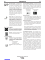
ARC RAYS can burn.
4.a. Use a shield with the proper filter and cover
plates to protect your eyes from sparks and
the rays of the arc when welding or observing
open arc welding. Headshield and filter lens
should conform to ANSI Z87. I standards.
4.b. Use suitable clothing made from durable flame-resistant
material to protect your skin and that of your helpers from
the arc rays.
4.c. Protect other nearby personnel with suitable, non-flammable
screening and/or warn them not to watch the arc nor expose
themselves to the arc rays or to hot spatter or metal.
ELECTRIC SHOCK can
kill.
3.a. The electrode and work (or ground) circuits
are electrically “hot” when the welder is on.
Do not touch these “hot” parts with your bare
skin or wet clothing. Wear dry, hole-free
gloves to insulate hands.
3.b. Insulate yourself from work and ground using dry insulation.
Make certain the insulation is large enough to cover your full
area of physical contact with work and ground.
In addition to the normal safety precautions, if welding
must be performed under electrically hazardous
conditions (in damp locations or while wearing wet
clothing; on metal structures such as floors, gratings or
scaffolds; when in cramped positions such as sitting,
kneeling or lying, if there is a high risk of unavoidable or
accidental contact with the workpiece or ground) use
the following equipment:
• Semiautomatic DC Constant Voltage (Wire) Welder.
• DC Manual (Stick) Welder.
• AC Welder with Reduced Voltage Control.
3.c. In semiautomatic or automatic wire welding, the electrode,
electrode reel, welding head, nozzle or semiautomatic
welding gun are also electrically “hot”.
3.d. Always be sure the work cable makes a good electrical
connection with the metal being welded. The connection
should be as close as possible to the area being welded.
3.e. Ground the work or metal to be welded to a good electrical
(earth) ground.
3.f.
Maintain the electrode holder, work clamp, welding cable and
welding machine in good, safe operating condition. Replace
damaged insulation.
3.g. Never dip the electrode in water for cooling.
3.h. Never simultaneously touch electrically “hot” parts of
electrode holders connected to two welders because voltage
between the two can be the total of the open circuit voltage
of both welders.
3.i. When working above floor level, use a safety belt to protect
yourself from a fall should you get a shock.
3.j. Also see Items 6.c. and 8.
FUMES AND GASES
can be dangerous.
5.a. Welding may produce fumes and gases
hazardous to health. Avoid breathing these
fumes and gases. When welding, keep
your head out of the fume. Use enough
ventilation and/or exhaust at the arc to keep
fumes and gases away from the breathing zone. When
welding with electrodes which require special
ventilation such as stainless or hard facing (see
instructions on container or MSDS) or on lead or
cadmium plated steel and other metals or coatings
which produce highly toxic fumes, keep exposure as
low as possible and within applicable OSHA PEL and
ACGIH TLV limits using local exhaust or mechanical
ventilation. In confined spaces or in some circum-
stances, outdoors, a respirator may be required.
Additional precautions are also required when welding
on galvanized steel.
5. b. The operation of welding fume control equipment is affected
by various factors including proper use and positioning of
the equipment, maintenance of the equipment and the spe-
cific welding procedure and application involved. Worker
exposure level should be checked upon installation and
periodically thereafter to be certain it is within applicable
OSHA PEL and ACGIH TLV limits.
5.c.
Do not weld in locations near chlorinated hydrocarbon
vapors
coming from degreasing, cleaning or spraying operations.
The heat and rays of the arc can react with solvent vapors
to
form phosgene, a highly toxic gas, and other irritating prod-
ucts.
5.d. Shielding gases used for arc welding can displace air and
cause injury or death. Always use enough ventilation,
especially in confined areas, to insure breathing air is safe.
5.e. Read and understand the manufacturer’s instructions for this
equipment and the consumables to be used, including the
material safety data sheet (MSDS) and follow your
employer’s safety practices. MSDS forms are available from
your welding distributor or from the manufacturer.
5.f. Also see item 1.b.

iii
SAFETY
iii
FOR ELECTRICALLY
powered equipment.
8.a. Turn off input power using the disconnect
switch at the fuse box before working on
the equipment.
8.b. Install equipment in accordance with the U.S. National
Electrical Code, all local codes and the manufacturer’s
recommendations.
8.c. Ground the equipment in accordance with the U.S. National
Electrical Code and the manufacturer’s recommendations.
CYLINDER may explode
if damaged.
7.a. Use only compressed gas cylinders
containing the correct shielding gas for the
process used and properly operating
regulators designed for the gas and
pressure used. All hoses, fittings, etc. should be suitable for
the application and maintained in good condition.
7.b. Always keep cylinders in an upright position securely
chained to an undercarriage or fixed support.
7.c. Cylinders should be located:
• Away from areas where they may be struck or subjected to
physical damage.
• A safe distance from arc welding or cutting operations and
any other source of heat, sparks, or flame.
7.d. Never allow the electrode, electrode holder or any other
electrically “hot” parts to touch a cylinder.
7.e. Keep your head and face away from the cylinder valve outlet
when opening the cylinder valve.
7.f. Valve protection caps should always be in place and hand
tight except when the cylinder is in use or connected for
use.
7.g. Read and follow the instructions on compressed gas
cylinders, associated equipment, and CGA publication P-l,
“Precautions for Safe Handling of Compressed Gases in
Cylinders,” available from the Compressed Gas Association
1235 Jefferson Davis Highway, Arlington, VA 22202.
WELDING and CUTTING
SPARKS can
cause fire or explosion.
6.a.
Remove fire hazards from the welding area.
If this is not possible, cover them to prevent
the welding sparks from starting a fire.
Remember that welding sparks and hot
materials from welding can easily go through small cracks
and openings to adjacent areas. Avoid welding near
hydraulic lines. Have a fire extinguisher readily available.
6.b. Where compressed gases are to be used at the job site,
special precautions should be used to prevent hazardous
situations. Refer to “Safety in Welding and Cutting” (ANSI
Standard Z49.1) and the operating information for the
equipment being used.
6.c. When not welding, make certain no part of the electrode
circuit is touching the work or ground. Accidental contact
can cause overheating and create a fire hazard.
6.d. Do not heat, cut or weld tanks, drums or containers until the
proper steps have been taken to insure that such procedures
will not cause flammable or toxic vapors from substances
inside. They can cause an explosion even
though
they have
been “cleaned”. For information, purchase “Recommended
Safe Practices for the
Preparation
for Welding and Cutting of
Containers and Piping That Have Held Hazardous
Substances”, AWS F4.1 from the American Welding Society
(see address above).
6.e. Vent hollow castings or containers before heating, cutting or
welding. They may explode.
6.f.
Sparks and spatter are thrown from the welding arc. Wear oil
free protective garments such as leather gloves, heavy shirt,
cuffless trousers, high shoes and a cap over your hair. Wear
ear plugs when welding out of position or in confined places.
Always wear safety glasses with side shields when in a
welding area.
6.g. Connect the work cable to the work as close to the welding
area as practical. Work cables connected to the building
framework or other locations away from the welding area
increase the possibility of the welding current passing
through lifting chains, crane cables or other alternate cir-
cuits. This can create fire hazards or overheat lifting chains
or cables until they fail.
6.h. Also see item 1.c.
6.I. Read and follow NFPA 51B “ Standard for Fire Prevention
During Welding, Cutting and Other Hot Work”, available
from NFPA, 1 Batterymarch Park, PO box 9101, Quincy, Ma
022690-9101.
6.j. Do not use a welding power source for pipe thawing.
Refer to http://www.lincolnelectric.com/safety for additional safety information.

iv
SAFETY
iv
PRÉCAUTIONS DE SÛRETÉ
Pour votre propre protection lire et observer toutes les instructions
et les précautions de sûreté specifiques qui parraissent dans ce
manuel aussi bien que les précautions de sûreté générales suiv-
antes:
Sûreté Pour Soudage A LʼArc
1. Protegez-vous contre la secousse électrique:
a. Les circuits à lʼélectrode et à la piéce sont sous tension
quand la machine à souder est en marche. Eviter toujours
tout contact entre les parties sous tension et la peau nue
ou les vétements mouillés. Porter des gants secs et sans
trous pour isoler les mains.
b. Faire trés attention de bien sʼisoler de la masse quand on
soude dans des endroits humides, ou sur un plancher
metallique ou des grilles metalliques, principalement dans
les positions assis ou couché pour lesquelles une grande
partie du corps peut être en contact avec la masse.
c. Maintenir le porte-électrode, la pince de masse, le câble
de soudage et la machine à souder en bon et sûr état
defonctionnement.
d.Ne jamais plonger le porte-électrode dans lʼeau pour le
refroidir.
e. Ne jamais toucher simultanément les parties sous tension
des porte-électrodes connectés à deux machines à souder
parce que la tension entre les deux pinces peut être le
total de la tension à vide des deux machines.
f. Si on utilise la machine à souder comme une source de
courant pour soudage semi-automatique, ces precautions
pour le porte-électrode sʼapplicuent aussi au pistolet de
soudage.
2. Dans le cas de travail au dessus du niveau du sol, se protéger
contre les chutes dans le cas ou on recoit un choc. Ne jamais
enrouler le câble-électrode autour de nʼimporte quelle partie
du corps.
3. Un coup dʼarc peut être plus sévère quʼun coup de soliel,
donc:
a. Utiliser un bon masque avec un verre filtrant approprié
ainsi quʼun verre blanc afin de se protéger les yeux du ray-
onnement de lʼarc et des projections quand on soude ou
quand on regarde lʼarc.
b. Porter des vêtements convenables afin de protéger la
peau de soudeur et des aides contre le rayonnement de
lʻarc.
c. Protéger lʼautre personnel travaillant à proximité au
soudage à lʼaide dʼécrans appropriés et non-inflammables.
4. Des gouttes de laitier en fusion sont émises de lʼarc de
soudage. Se protéger avec des vêtements de protection libres
de lʼhuile, tels que les gants en cuir, chemise épaisse, pan-
talons sans revers, et chaussures montantes.
5. Toujours porter des lunettes de sécurité dans la zone de
soudage. Utiliser des lunettes avec écrans lateraux dans les
zones où lʼon pique le laitier.
6. Eloigner les matériaux inflammables ou les recouvrir afin de
prévenir tout risque dʼincendie dû aux étincelles.
7. Quand on ne soude pas, poser la pince à une endroit isolé de
la masse. Un court-circuit accidental peut provoquer un
échauffement et un risque dʼincendie.
8. Sʼassurer que la masse est connectée le plus prés possible
de la zone de travail quʼil est pratique de le faire. Si on place
la masse sur la charpente de la construction ou dʼautres
endroits éloignés de la zone de travail, on augmente le risque
de voir passer le courant de soudage par les chaines de lev-
age, câbles de grue, ou autres circuits. Cela peut provoquer
des risques dʼincendie ou dʼechauffement des chaines et des
câbles jusquʼà ce quʼils se rompent.
9. Assurer une ventilation suffisante dans la zone de soudage.
Ceci est particuliérement important pour le soudage de tôles
galvanisées plombées, ou cadmiées ou tout autre métal qui
produit des fumeés toxiques.
10. Ne pas souder en présence de vapeurs de chlore provenant
dʼopérations de dégraissage, nettoyage ou pistolage. La
chaleur ou les rayons de lʼarc peuvent réagir avec les vapeurs
du solvant pour produire du phosgéne (gas fortement toxique)
ou autres produits irritants.
11. Pour obtenir de plus amples renseignements sur la sûreté,
voir le code “Code for safety in welding and cutting” CSA
Standard W 117.2-1974.
PRÉCAUTIONS DE SÛRETÉ POUR
LES MACHINES À SOUDER À
TRANSFORMATEUR ET À
REDRESSEUR
1. Relier à la terre le chassis du poste conformement au code de
lʼélectricité et aux recommendations du fabricant. Le dispositif
de montage ou la piece à souder doit être branché à une
bonne mise à la terre.
2. Autant que possible, Iʼinstallation et lʼentretien du poste seront
effectués par un électricien qualifié.
3. Avant de faires des travaux à lʼinterieur de poste, la debranch-
er à lʼinterrupteur à la boite de fusibles.
4. Garder tous les couvercles et dispositifs de sûreté à leur
place.

v
SAFETY
v
Electromagnetic Compatibility (EMC)
Conformance
Products displaying the CE mark are in conformity with European Community Council Directive of 15 Dec
2004 on the approximation of the laws of the Member States relating to electromagnetic compatibility,
2004/108/EC. It was manufactured in conformity with a national standard that implements a harmonized
standard: EN 60974-10 Electromagnetic Compatibility (EMC) Product Standard for Arc Welding Equipment.
It is for use with other Lincoln Electric equipment. It is designed for industrial and professional use.
Introduction
All electrical equipment generates small amounts of electromagnetic emission. Electrical emission may be
transmitted through power lines or radiated through space, similar to a radio transmitter. When emissions
are received by other equipment, electrical interference may result. Electrical emissions may affect many
kinds of electrical equipment; other nearby welding equipment, radio and TV reception, numerical controlled
machines, telephone systems, computers, etc.
WARNING: This equipment is not intended for use in residential locations where the electrical power is pro-
vided by the public low-voltage supply system. There may be potential difficulties in ensuring electromagnet-
ic compatibility in those locations, due to conducted as well as radiated disturbances.
Installation and Use
The user is responsible for installing and using the welding equipment according to the manufacturer’s
instructions. If electromagnetic disturbances are detected then it shall be the responsibility of the user of the
welding equipment to resolve the situation with the technical assistance of the manufacturer. In some cases
this remedial action may be as simple as earthing (grounding) the welding circuit, see Note. In other cases it
could involve construction of an electromagnetic screen enclosing the power source and the work complete
with associated input filters. In all cases electromagnetic disturbances must be reduced to the point where
they are no longer troublesome.
Note: The welding circuit may or may not be earthed for safety reasons. Follow your local and
national standards for installation and use. Changing the earthing arrangements should only
be authorized by a person who is competent to assess whether the changes will increase the
risk of injury, e.g., by allowing parallel welding current return paths which may damage the
earth circuits of other equipment.
Assessment of Area
Before installing welding equipment the user shall make an assessment of potential electromagnetic prob-
lems in the surrounding area. The following shall be taken into account:
a) other supply cables, control cables, signaling and telephone cables; above, below and adjacent to the
welding equipment;
b) radio and television transmitters and receivers;
c) computer and other control equipment;
d) safety critical equipment, e.g., guarding of industrial equipment;
e) the health of the people around, e.g., the use of pacemakers and hearing aids;
f) equipment used for calibration or measurement;
g) the immunity of other equipment in the environment. The user shall ensure that other equipment being
used in the environment is compatible. This may require additional protection measures;
h) the time of day that welding or other activities are to be carried out.

vi
SAFETY
vi
Electromagnetic Compatibility (EMC)
The size of the surrounding area to be considered will depend on the structure of the building and other
activities that are taking place. The surrounding area may extend beyond the boundaries of the premises.
Methods of Reducing Emissions
Public Supply System
Welding equipment should be connected to the public supply system according to the manufacturer’s rec-
ommendations. If interference occurs, it may be necessary to take additional precautions such as filtering of
the public supply system. Consideration should be given to shielding the supply cable of permanently
installed welding equipment, in metallic conduit or equivalent. Shielding should be electrically continuous
throughout its length. The shielding should be connected to the welding power source so that good electrical
contact is maintained between the conduit and the welding power source enclosure.
Maintenance of the Welding Equipment
The welding equipment should be routinely maintained according to the manufacturer’s recommendations.
All access and service doors and covers should be closed and properly fastened when the welding equip-
ment is in operation. The welding equipment should not be modified in any way except for those changes
and adjustments covered in the manufacturers instructions. In particular, the spark gaps of arc striking and
stabilizing devices should be adjusted and maintained according to the manufacturer’s recommendations.
Welding Cables
The welding cables should be kept as short as possible and should be positioned close together, running at
or close to floor level.
Equipotential Bonding
Bonding of all metallic components in the welding installation and adjacent to it should be considered.
However, metallic components bonded to the work piece will increase the risk that the operator could
receive a shock by touching these metallic components and the electrode at the same time. The operator
should be insulated from all such bonded metallic components.
Earthing of the Workpiece
Where the workpiece is not bonded to earth for electrical safety, nor connected to earth because of its size
and position, e.g., ship’s hull or building steelwork, a connection bonding the workpiece to earth may reduce
emissions in some, but not all instances. Care should be taken to prevent the earthing of the workpiece
increasing the risk of injury to users, or damage to other electrical equipment. Where necessary, the connec-
tion of the workpiece to earth should be made by a direct connection to the workpiece, but in some countries
where direct connection is not permitted, the bonding should be achieved by suitable capacitance, selected
according to national regulations.
Screening and Shielding
Selective screening and shielding of other cables and equipment in the surrounding area may alleviate prob-
lems of interference. Screening of the entire welding installation may be considered for special applica-
tions1.
_________________________
1 Portions of the preceding text are contained in EN 60974-10: “Electromagnetic Compatibility (EMC) prod-
uct standard for arc welding equipment.”

viivii
Thank You
for selecting a QUALITY product by Lincoln Electric. We want you
to take pride in operating this Lincoln Electric Company product
••• as much pride as we have in bringing this product to you!
Read this Operators Manual completely before attempting to use this equipment. Save this manual and keep it
handy for quick reference. Pay particular attention to the safety instructions we have provided for your protection.
The level of seriousness to be applied to each is explained below:
WARNING
This statement appears where the information must be followed exactly to avoid serious personal injury or loss of life.
This statement appears where the information must be followed to avoid minor personal injury or damage to this equipment.
CAUTION
Please Examine Carton and Equipment For Damage Immediately
When this equipment is shipped, title passes to the purchaser upon receipt by the carrier. Consequently, Claims
for material damaged in shipment must be made by the purchaser against the transportation company at the
time the shipment is received.
Please record your equipment identification information below for future reference. This information can be
found on your machine nameplate.
Product _________________________________________________________________________________
Model Number ___________________________________________________________________________
Code Number or Date Code_________________________________________________________________
Serial Number____________________________________________________________________________
Date Purchased___________________________________________________________________________
Where Purchased_________________________________________________________________________
Whenever you request replacement parts or information on this equipment, always supply the information you
have recorded above. The code number is especially important when identifying the correct replacement parts.
On-Line Product Registration
- Register your machine with Lincoln Electric either via fax or over the Internet.
• For faxing: Complete the form on the back of the warranty statement included in the literature packet
accompanying this machine and fax the form per the instructions printed on it.
• For On-Line Registration: Go to our
WEB SITE at www.lincolnelectric.com. Choose “Support” and then “Register
Your Product”. Please complete the form and submit your registration.
CUSTOMER ASSISTANCE POLICY
The business of The Lincoln Electric Company is manufacturing and selling high quality welding equipment, consumables, and cutting equip-
ment. Our challenge is to meet the needs of our customers and to exceed their expectations. On occasion, purchasers may ask Lincoln
Electric for advice or information about their use of our products. We respond to our customers based on the best information in our posses-
sion at that time. Lincoln Electric is not in a position to warrant or guarantee such advice, and assumes no liability, with respect to such infor-
mation or advice. We expressly disclaim any warranty of any kind, including any warranty of fitness for any customerʼs particular purpose,
with respect to such information or advice. As a matter of practical consideration, we also cannot assume any responsibility for updating or
correcting any such information or advice once it has been given, nor does the provision of information or advice create, expand or alter any
warranty with respect to the sale of our products.
Lincoln Electric is a responsive manufacturer, but the selection and use of specific products sold by Lincoln Electric is solely within the control
of, and remains the sole responsibility of the customer. Many variables beyond the control of Lincoln Electric affect the results obtained in
applying these types of fabrication methods and service requirements.
Subject to Change – This information is accurate to the best of our knowledge at the time of printing. Please refer to www.lincolnelectric.com
for any updated information.

viii
viii TABLE OF CONTENTS
Page
Installation.......................................................................................................................Section A
Technical Specifications.......................................................................................................A-1
Select Suitable Location.......................................................................................................A-2
Stacking................................................................................................................................A-2
Tilting....................................................................................................................................A-2
Environmental Area..............................................................................................................A-2
Machine Grounding and High Frequency Interference Protection .......................................A-2
Input Connections ................................................................................................................A-3
Reconnect Procedure...........................................................................................................A-3
Input Plug Installation ...........................................................................................................A-4
Engine Drive Generator........................................................................................................A-4
Output Connections..............................................................................................................A-5
Output and Gas Connection for Tig Welding........................................................................A-5
Work Cable Connection .......................................................................................................A-5
Output Connection for Stick Welding ...................................................................................A-5
Quick Disconnect Plug .........................................................................................................A-6
Shielding Gas Connection....................................................................................................A-6
Remote Control Connection .................................................................................................A-6
________________________________________________________________________________
Operation.........................................................................................................................Section B
Safety Instructions................................................................................................................B-1
General Description..............................................................................................................B-1
Welding Capability................................................................................................................B-1
Limitations ............................................................................................................................B-1
Rear Control Panel...............................................................................................................B-2
Lower Control Panel.............................................................................................................B-2
User Interface Overview and Operation ...............................................................................B-3
Dynamic LCD Display ...........................................................................................B-4, B-5, B-6
Welding Parameter ..............................................................................................................B-7
User Menu Set Up Parameters ............................................................................................B-8
Set Up Menu Parameters, Optional Cool-Arc 35 Water Cooler..................................B-9, B-10
Tips For Improved TIG Starting, Stick Crisp Mode Dynamic Current Regulation .............B-11
________________________________________________________________________________
Accessories.....................................................................................................Section C
Optional Accessories and Compatible Equipment ................................................C-1
Factory, Field Installed...................................................................................C-1, C-2
________________________________________________________________________
Maintenance ....................................................................................................Section D
Safety Precautions ................................................................................................D-1
Input Filter Capacitor Discharge Procedure ..........................................................D-1
Routine Maintenance.............................................................................................D-1
________________________________________________________________________
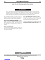
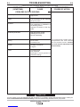
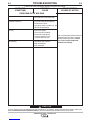
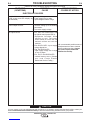
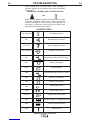
Troubleshooting..............................................................................................Section E
How to Use Troubleshooting Guide.......................................................................E-1
Troubleshooting Guide.............................................................................E-2 thru E-5
________________________________________________________________________
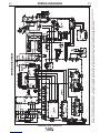
Wiring Diagram ...............................................................................................Section F
________________________________________________________________________
Parts Lists...............................................................................................................P-643
________________________________________________________________________

A-1
INSTALLATION
INVERTEC® V311-T AC/DC TIG
A-1
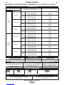
Input Current @ Rated Output
7.3A
8.3A
12.3A
9.6A
10.7A
13.8A
13.9A
15.8A
24.6A
18.7A
20.9A
27.7A
15.3A
17.5A
27.3A
20.5A
23.6A
30.8A
13.6A
14.9A
23.1A
17.2A
19.4A
25.7A
21.9A
24.6A
41.5A
29.2A
33.2A
47.1A
24.2A
27.7A
47.3A
32.1A
37.3A
52.5A
Rated Output Current, Voltage,
Duty Cycle (104°F, 40°C)
210A / 18.4V / 100%
TIG 230A / 19.2V / 60%
310A / 22.4V / 40%
200A / 28.0V / 100%
STICK 220A / 28.8V / 60%
270A / 30.8V / 40%
210A / 18.4V / 100%
TIG 230A / 19.2V / 60%
310A / 22.4V / 30%
200A / 28.0V / 100%
STICK 220A / 28.8V / 60%
270A / 30.8V / 35%
210A / 18.4V / 100%
TIG 230A / 19.2V / 60%
310A / 22.4V / 30%
200A / 28.0V / 100%
STICK 220A / 28.8V / 60%
270A / 30.8V / 35%
200A / 18.0V / 100%
TIG 220A / 18.8V / 60%
310A /22.4V / 35%
190A / 27.6V / 100%
STICK 210A / 28.4V / 60%
270A / 30.8V / 35%
200A / 18.0V / 100%
TIG 220A / 18.8V / 60%
310A / 22.4V / 25%
190A / 27.6V / 100%
STICK 210A / 28.4V / 60%
270A / 30.8V / 30%
200A / 18.0V / 100%
TIG 220A / 18.8V / 60%
310A / 22.4V / 25%
190A / 27.6V / 100%
STICK 210A / 28.4V / 60%
270A / 30.8V / 30%
Maximum Open Circuit Voltage
80 Volts Max.
Type of Output
AC/DC
Phase
Three-
Phase
Single-
Phase
Voltage/ Hertz
460/50/60
230/50/60
208/50/60
460/50/60
230/50/60
208/50/60
Input Power
Output Current Range
5-310 Amps
RATED OUTPUT
OUTPUT RANGE
Height Width Depth Weight
17.0 in. 11.0 in. 24.5 in. Approx. 75 lbs.
432 mm 280 mm 622 mm 34.0 kgs.
PHYSICAL DIMENSIONS
TECHNICAL SPECIFICATIONS - INVERTEC®V311-T AC/DC TIG K2915-1
TEMPERATURE RANGES
OPERATING TEMPERATURE RANGE
-20°C to +40°C
STORAGE TEMPERATURE RANGE
-50°C to +85°C
Type S, SO, STO, or other EXTRA
HARD USAGE Input Cord
10 AWG, 4 Conductor
Maximum Time-Delay Circuit
Breaker or Fuse Size (Amps)
60
Input Voltage/Frequency (Hz)
208/230/460/50/60
RECOMMENDED INPUT WIRE AND FUZE SIZES FOR MAXIMUM OUTPUT

A-2
INSTALLATION
INVERTEC® V311-T AC/DC TIG
A-2
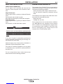
MACHINE GROUNDING AND HIGH FRE-
QUENCY INTERFERENCE PROTECTION
The Capacitor Discharge Circuit used in the high fre-
quency generator, may cause many radio, TV and
electronic equipment interference problems. These
problems may be the result of radiated interference.
Proper grounding methods can reduce or eliminate
radiated interference.
The Invertec® V311-T AC/DC TIG has been field test-
ed under recommended installation conditions. It com-
plies with FCC allowable limits for radiation.
Radiated interference can develop in the following
four ways:
1. Direct interference radiated from the welder.
2. Direct interference radiated from the welding leads.
3. Direct interference radiated from feedback into the
power lines.
4. Interference from re-radiation of “pickup” by
ungrounded metallic objects.
Keeping these contributing factors in mind, installing
equipment per the following instructions should mini-
mize problems.
1. Keep the welder power supply lines as short as
possible and enclose as much of them as possible
in rigid metallic conduit or equivalent shielding for a
distance of 50 feet (15.2m). There should be good
electrical contact between this conduit and the
welder case ground. Both ends of the conduit
should be connected to a driven ground and the
entire length should be continuous.
2. Keep the work and electrode leads as short as
possible and as close together as possible.
Lengths should not exceed 25 ft (7.6m).
3. Be sure the torch and work cable rubber cover-
ings are free of cuts and cracks that allow high
frequency leakage. Cables with high natural rub-
ber content, such as Lincoln Stable-Arc®better
resist high frequency leakage than neoprene and
other synthetic rubber insulated cables.
4. Keep the torch in good repair and all connections
tight to reduce high frequency leakage.
Read entire installation section before starting
installation.
Safety Precautions
------------------------------------------------------------
SELECT SUITABLE LOCATION
The Invertec® V311-T AC/DC TIG will operate in
harsh environments. Even so, it is important that sim-
ple preventative measures are followed in order to
assure long life and reliable operation.
• The machine must be located where there is free cir-
culation of clean air such that air movement in the
back and out the front will not be restricted.
• Dirt and dust that can be drawn into the machine
should be kept to a minimum. Failure to observe
these precautions can result in excessive operating
temperatures and nuisance shutdown.
STACKING
The Invertec® V311-T AC/DC TIG can not be
stacked.
TILTING
Place the machine directly on a secure, level surface.
The machine may topple over if this procedure is not
followed.
ENVIRONMENTAL AREA
Keep the machine dry. Do not place it on wet ground
or in puddles.
ELECTRIC SHOCK can kill.
• Only qualified personnel should per-
form this installation.
• Turn the input power OFF and
unplug the machine from the recep-
tacle before working on this equip-
ment. Allow machine to sit for 5 min-
utes
minimum to allow the power
capacitors to discharge before
working inside this equipment.
•
Insulate yourself from the work and ground.
•
Always wear dry insulating gloves.
• Always connect the
Invertec®
V311-T
AC/DC TIG
to a power supply grounded according to the
National Electrical Code and local codes.
WARNING

A-3
INSTALLATION
INVERTEC® V311-T AC/DC TIG
A-3
5. The work terminal must be connected to a ground
within ten feet of the welder, using one of the fol-
lowing methods.
a) A metal underground water pipe in direct con-
tact with the earth for ten feet or more.
b) A 3/4” (19mm) galvanized pipe or a 5/8”
(16mm) solid galvanized iron, steel or copper
rod driven at least eight feet into the ground.
The ground should be securely made and the
grounding cable should be as short as possible
using cable of the same size as the work cable, or
larger. Grounding to the building frame electrical
conduit or a long pipe system can result in re-radi-
ation, effectively making these members radiating
antennas.
6. Keep all panels securely in place.
7. All electrical conductors within 50 ft (15.2m) of the
welder should be enclosed in grounded, rigid
metallic conduit or equivalent shielding. Flexible
metallic conduit is generally not suitable.
8. When the welder is enclosed in a metal building,
several earth driven electrical grounds connected
(as in 5b above) around the periphery of the build-
ing are recommended.
Failure to observe these recommended installation
procedures can cause radio or TV interference prob-
lems.
RECONNECT PROCEDURE
The Invertec® V311-T AC/DC auto reconnects to
208V, 230V or 460V supply.
Fuse the input circuit with time delay fuses or delay
type1circuit breakers. Using fuses or circuit breakers
smaller than recommended may result in “nuisance”
shut-offs from welder inrush currents even if not weld-
ing at high currents.
The Invertec® V311-T AC/DC is recommended for
use on an individual branch circuit.
¹ Also called “inverse time” or “thermal/magnetic” circuit breakers.
These circuit breakers have a delay in tripping action that
decreases as the magnitude of the current increases.
INPUT CONNECTIONS
Be sure the voltage, phase, and frequency of the input
power is as specified on the rating plate, located on
the bottom of the machine.
ELECTRIC SHOCK can kill.
• Have a qualified electrician install
and service this equipment.
• Turn the input power OFF and unplug
the machine from the receptacle
before working on this equipment.
• Allow machine to sit for 5 minutes
minimum to
allow the power capacitors to discharge before
working inside this equipment.
• Do not touch electrically hot parts.
• Machine must be plugged into a receptacle that
is grounded according to the National Electrical
Code and local codes.
• Do not remove or defeat the purpose of the
power cord ground pin.
------------------------------------------------------------
WARNING

A-4
INSTALLATION
INVERTEC® V311-T AC/DC TIG
A-4
INPUT PLUG INSTALLATION
POWER CORD CONNECTION
A 10 ft. power cord is provided and wired into the
machine. Follow the power cord connection instruc-
tions.
Single Phase Input
Connect green lead to ground per National Electrical
Code.
Connect black and red leads to power.
Wrap white lead with tape to provide 600V insulation.
Three Phase Input
Connect green lead to ground per National Electric
Code.
Connect black, red and white leads to power.
•
Failure to wire as instructed may cause personal
injury or damage to equipment. To be installed
or checked by an electrician or qualified person
only.
------------------------------------------------------------
In all cases, the green or green/yellow grounding wire
must be connected to the grounding pin of the plug, usu-
ally identified by a green screw.
Attachment plugs must comply with the Standard for
Attachment Plugs and Receptacles, UL498.
The product is considered acceptable for use only when
an attachment plug as specified is properly attached to
the supply cord.
For use on engine drives, keep in mind the above input
draw restrictions and the following precaution.
ENGINE DRIVEN GENERATOR
The Invertec® V311-T AC/DC TIG can be operated on
engine driven generators as long as the 230 volt auxil-
iary meets the following conditions:
• The AC waveform peak voltage is below 400 volts.
• The AC waveform frequency is between 45 and
65Hz.
The following Lincoln engine drives meet these condi-
tions when run in the high idle mode:
• Ranger 250, 305
• Vantage 300, 400, 500
Some engine drives do not meet these conditions
(e.g. Miller Bobcats, etc). Operation of the Invertec®
V311-T AC/DC is not recommended on engine drives
not conforming to these conditions. Such drives may
deliver unacceptably high voltage levels to the
Invertec® V311-T AC/DC power source.
WARNING

OUTPUT CONNECTIONS
ELECTRIC SHOCK can kill.
• Insulate yourself from work and
ground.
• Turn the input line Switch on the
Invertec® V311T AC/DC “off” before
connecting or disconnecting output
cables or other equipment.
• Keep the electrode holder, TIG torch and cable
insulation in good condition and in place.
• Do not touch electrically live parts or electrode
with skin or wet clothing.
------------------------------------------------------------
A-5
INSTALLATION
INVERTEC® V311-T AC/DC TIG
A-5
This unit does not include a TIG torch, but one may be
purchased separately. The accessories section of this
manual lists a number of Lincoln Electric TIG torches,
and TIG Torch Starter Packs that are recommended
for use with this machine; however, any similar TIG
torch can be used. To attach the Twist-Mate Plug to a
Lincoln Torch, slide the rubber boot onto the torch
cable (enlarge the boot opening if necessary), screw
the fitting on the torch cable into the brass connector
snugly and slide the boot back over the brass connec-
tor.
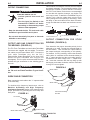
OUTPUT CONNECTION FOR STICK
WELDING (FIGURE A.2)
First determine the proper electrode polarity for the
electrode to be used. Consult the electrode data for
this information. Then connect the output cables to
the output terminals corresponding to this polarity.
For instance, for DC(+) welding, connect the electrode
cable (which is connected to the electrode holder) to
the “+” output terminal and the work cable (which is
connected to the work clamp) to the “-” output termi-
nal. Insert the connector with the key lining up with
the keyway, and rotate clockwise; until the connection
is snug. Do not over tighten.
TIG ADAPTER
RETAINING COMPOUND
STRAIN RELIEF BOOT
TIG TORCH POWER CABLE WITH GAS FITING
FIGURE A.2
WORK CABLE
WORK CABLE
WORK CLAMP
STICK ELECTRODE
HOLDER
WORK CABLE
TIG TORCH
WARNING
OUTPUT AND GAS CONNECTION FOR
TIG WELDING (FIGURE A.1)
The TIG Torch Twist-Mate and work cable Twist-Mate
Connectors are supplied with the welder. To connect
the cables, turn the Power Switch“OFF”.
Connect the
torch cable Twist-Mate plug into the DC(-)
Electrode/Gas Output Receptacle on the front of the
welder and turn it clockwise until snug,(Do not
Overtighten). This is a quick connect terminal and also
provides the gas connection for the shielding gas to
the torch.
To avoid receiving a high frequency shock, keep
the TIG torch and cable Insulation in good condi-
tion.
___________________________________________
WORK CABLE CONNECTION
Next, connect the work cable to the “+” output terminal
in the same way.
To minimize high frequency interference, refer to
Machine Grounding and High Frequency
Interference Protection section of this manual for the
proper procedure on grounding the work clamp and
work piece.
WARNING
FIGURE A.1

A-6
INSTALLATION
INVERTEC® V311-T AC/DC TIG
A-6
REMOTE CONTROL CONNECTION
A remote control receptacle is provided on the lower
center case front of the welder for connecting a
remote control to the machine. Refer to the Optional
Accessories section of this manual for available
remote controls.
CYLINDER could explode
if damaged.
• Keep cylinder upright and
chained to a support.
• Keep cylinder away from areas where it
could be damaged.
• Never allow the torch or welding electrode
to touch the cylinder.
• Keep cylinder away from live electrical cir-
cuits.
------------------------------------------------------------
WARNING
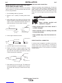
QUICK DISCONNECT PLUG (FOR STICK ELEC-
TRODE CABLE and WORK CABLE)
A quick disconnect system is used for the welding
cable connections. The stick electrode cable will need
to have a plug attached.
1. Cut off welding cable lug, if present.
2. Remove 1.00 in. (25mm) of welding cable insula-
tion.
3. Slide rubber boot onto cable end. The boot end
may be trimmed to match the cable diameter. Use
soap or other nonpetroleum-based lubricant to
help slide the boot over the cable, if needed.
4. Insert copper strands into ferrule.
5. Slide the copper ferrule into the brass plug.
6. Tighten set screw to collapse copper tube. Screw
must apply pressure against welding cable. The
top of the set screw will be well below the surface
of the brass plug after tightening.
7. Slide rubber boot over brass plug. The rubber boot
must be positioned to completely cover all electri-
cal surfaces after the plug is locked into the recep-
tacle.
25 mm
1.00 in.
WELDING CABLE
BOOT
TRIM, IF REQ'D
TO FIT OVER CABLE
WELDING CABLE
COPPER FERRULE
SET SCREW
BRASS PLUG
COPPER TUBE
SHIELDING GAS CONNECTION
Obtain the necessary inert shielding gas. Connect the
cylinder of gas with a pressure regulator and flow
gage. Install a gas hose between the regulator and
gas inlet (located on the rear of the welder). The gas
inlet has a 5/16-18 right hand female thread; CGA
#032.

B-1
OPERATION
INVERTEC® V311-T AC/DC TIG
B-1
Read and understand this entire section before
operating your machine.
SAFETY INSTRUCTIONS
ELECTRIC SHOCK can kill.
• Do not touch electrically live parts
such as output terminals, electrode
or internal wiring.
• Insulate yourself from the work and
ground.
• Always wear dry insulating gloves.
------------------------------------------------------------
------------------------------------------------------------
------------------------------------------------------------
------------------------------------------------------------
Only qualified personnel should operate this
equipment. Observe all safety information
throughout this manual.
GENERAL DESCRIPTION
The Invertec® V311-T AC/DC is an industrial 310 amp
arc welding power source that utilizes single or three
phase input power, to produce constant current out-
put. The welding response has been optimized for
stick (SMAW) and TIG (GTAW). The unit is ideal for
industrial applications where portability, high efficiency
and premium arc performance is important.
The Invertec® V311-T AC/DC is a power source that
can perform the following types of welding with excel-
lent results:
• TIG AC with square, sinusoidal and triangular
waveforms.
• TIG DC (with high frequency or Touch Start TIG
Starting)
• Stick DC & Stick AC
WELDING CAPABILITY
The Invertec® V311-T AC/DC is rated at 310 amps,
22.4 volts, at 40% duty cycle on a ten minute basis
when connected to a 460V three phase supply line. It
is capable of higher duty cycles at lower output cur-
rents. If the duty cycle is exceeded, a thermal protec-
tor will shut off the output until the machine cools. See
Technical Specifications in A-1 for other rated outputs.
The Invertec® V311-T AC/DC is recommended for
stick welding with such popular electrodes as
Fleetweld 5P and 5P+ (E6010), Fleetweld 35 (E6011),
Fleetweld 37 (E6013), Fleetweld 180 (E6011) and
Excalibur 7018.
LIMITATIONS
The Invertec® V311-T AC/DC is not recommended for
pipe thawing.
WARNING
FUMES AND GASES
can be dangerous.
• Keep your head out of fumes.
• Use ventilation or exhaust to
remove fumes from breathing
zone.
ARC RAYS
can burn.
• Wear eye, ear and body
protection.
WELDING, CUTTING and
GOUGING SPARKS
can cause fire or explosion
• Keep flammable material away.
• Do not weld, cut or gouge on
containers that have held com-
bustibles.

B-2
OPERATION
B-2
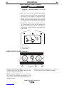
REAR CONTROL PANEL (FIGURE B.1)
• I1: Off/On switch turns on the electric power to
the welder. It has two positions, "O" off, and
"I" on.
------------------------------------------------------------
*With "l1" in the "I" (ON) position, the welding
machine is operational and there is voltage between
the positive (+) and negative (-) Terminals in stick
welding. In TIG, the welding process needs a trigger
closure command at the remote control connec-
tion.(Usually via an Arc Start Switch or Foot Amptrol)
*The welder is connected to the supply even if the
“l1” (Power Switch) is in the "O" (Off) position, and
therefore there are electrically live parts inside the
power source. Carefully follow the instructions given
in this manual.
FIGURE B.1
*1: Supply cable
*2: Gas attachment
l1 : Power Switch
LOWER CONTROL PANEL (FIGURE B.2)
1. Electrode Connection (Negative) - For quick dis-
connect system using Twist-Mate cable plugs with
gas pass through for TIG Torches.
2. Remote Control Connector - For the connection
of a Lincoln Foot Amptrol, Hand Amptrol or Arc
Start Switch. See the ACCESSORIES section for
available options.
3. Electrode Connection (Positive) - For quick dis-
connect system using Twist-Mate cable plugs.
INVERTEC® V311-T AC/DC TIG
1
2I1
WARNING
123
FIGURE B.2

B-3
OPERATION
B-3
INVERTEC® V311-T AC/DC TIG
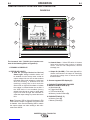
The Invertec® V311-T AC/DC User interface con-
sists of the following (Refer to Figure B.3):
1. DYNAMIC LCD DISPLAY
2. STATUS LED LIGHTS
a. VRD On (Voltage Reduction Device)
Status Light- Voltage reduction device can
be enabled from the set-up menu so that an
output voltage limit can be set that reduces
the output open circuit voltage to a safer level
when not welding. If enabled when the
machine is sitting idle in stick mode the
Green VRD on light will illuminate to indicate
the voltage is reduced below the set limit. If
the VRD device is not enabled (factory
default) from the set up menu or while weld-
ing the red VRD off light will illuminate to
show that output voltage is present above the
limit.
Note: The green VRD on light will illuminate in TIG
mode until the output is triggered even when VRD
is disabled. Also note that enabling VRD to reduce
the output voltage can make striking a stick elec-
trode more difficult.
b. General Alarm – Yellow LED which is lit when
faults exist with the power source or optional
cooler, such as over temperature, coolant
blockage, etc.
c. Output On (No VRD) – This status light will illu-
minate red whenever the output in electrically
hot and the voltage level is above the VRD
threshold value.
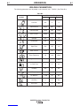
3. A seven segment LED display (H)
4. PUSH BUTTON/ROTARY ENCODER
5. MODE PUSH BUTTONS (A-D)
a. Weld Mode (A)
b. Trigger Mode (B)
c. TIG Pulse Mode (C)
d. Memory Location Select (D)
6. PUSH BUTTONS (E, F)
e. Memory Save (E)
f. Memory Recall (F)
USER INTERFACE OVERVIEW AND OPERATION:
1
3
4
5
2
6
ABCD EF
V311-T
AC/DC
I
IN V E R T E C
R
FIGURE B.3

B-4
OPERATION
B-4
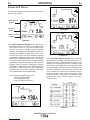
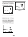
DYNAMIC LCD DISPLAY
The Dynamic display is divided into several sections
(Refer to Figure B.4):
Figure B.4
1. The Weld Sequence Diagram shows the various
parameters that can be selected and adjusted and
their preset values. As the push button/rotary
encoder is pressed a triangular shaped flashing
indicator will highlight the adjustable parameter on
the sequence diagram in bold. Each press of the
encoder will scroll to the next selected parameter
sequentially. Rotating the push button encoder will
change the selected parameter value. The display
is dynamic in that adjusting the selected parameter
dynamically changes the shape of the sequence
diagram. After 5 seconds of inactivity the selected
parameter will default back to the weld output amps
parameter. Depressing the button again will
remember the last selected parameter and begin
the sequential scroll from that parameter.
Three Sequence Diagram types exist:
• STICK (See Figure B.4a)
• TIG (See Figure B.4b)
• Pulse TIG (See Figure B.4c)
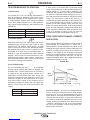
2. The Parameter Display Section shows the select-
ed parameter its display icon and preset value. To
change the value, rotate the push button/rotary
encoder. Some parameters like AC Frequency have
an Enhanced Icon Display that shows the effect of the
varying parameter on the arc and/or weld bead profile.
As these parameters are adjusted an indicator will
move between the minimum and maximum icon to
show the relative effect of that parameter. Pulse
Frequency shown in Figure B.4c is an example of the
enhanced icon display. Refer to Table B.1 for a list of
Enhanced Icons.
INVERTEC® V311-T AC/DC TIG
0.0s
0.2s
14A
72A 4.3Hz
50%
50%
5.0s
5A
10.0s
1. Weld Sequence
Diagram
2. Parameter
Display
3. Mode Push Button
Indicators
80%
30%
10A 10A
100Hz
10.0s
0.2s
f
+-
75%
97A
10A
100Hz
10.0s
0.2s
f
+-
75%
70A
50%
50%
10A
0.2Hz
.
.
.
..
.
.
.
..
.
.
..
.
.
.
.
Figure B.4a
Figure B.4b
Figure B.4c
Table B.1

B-5
OPERATION
B-5
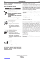
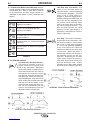
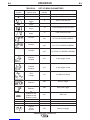
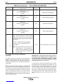
3. The Mode Push Buttons and Indicators show the
current selection made by the corresponding weld
push buttons (A-F). Refer to Table B.2 for a full list
of all parameters and their ranges. Below is a
description of the function of each push button and
display:
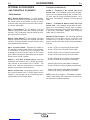
Two-Step with Foot Pedal -This
mode is only available when the
machine senses a remote amperage
control device is plugged in. It is used
when a foot or hand amptrol is
plugged in. When this trigger mode is
selected, upslope and downslope are
set to zero and non-adjustable since
the operator would manually adjust
ramp up and ramp down of the weld-
ing current using the amptrol. The
start and finish currents are linked
together and are repesented by a
parameter called Minimum Current.
(Refer to Figure B.5)
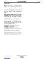
Four Step - This mode is intended to
be used with an arc start switch. It will
not function properly in remote mode
with a foot or hand amptrol plugged
in. In four step operation depressing
an arc start switch will cause the
machine to initiate the arc at the start
current level. When the switch is
released the machine will ramp up to
the maximum current over the ups-
lope time. Depressing the arc start
switch again causes the output to
ramp down to the finish current level
over the downslope time. Finally
releasing the arc start switch causes
the arc to go out. (Refer to Figure B.6)
INVERTEC® V311-T AC/DC TIG
Table B.2
DC TIG - DC TIG welding with high
frequency arc initiation.
AC TIG - AC TIG welding with high
frequency arc initiation.
DC Touch Start TIG - DC TIG welding with
lift tig arc initiation.
Stick crisp mode - for Cellulosic electrodes
like Exx10.
Stick soft mode - for E7018 Low Hydrogen
electrodes.
AC Stick Mode - for AC Stick Electrodes.
A. WELDING MODES
B. TIG TRIGGER MODES
Two Step with Arc Start Switch -
This mode is available in local or
remote modes but is typically used
with an arc start switch. Depressing
the arc start switch will initiate the arc
at the start current level and ramp up
the output to the maximum current
over the time set by the upslope time.
Releasing the switch will cause the
output amperage to ramp down to the
finish current over the downslope time
and then turn off the output. In this
mode the start current and finish cur-
rent can be independently set and
upslope and downslope times are
adjustable. (Refer to Figure B.5)
2S
2S
2S
FIGURE B.5 2-STEP OPERATION SEQUENCE
PRE-FLOW PRE-FLOWPRE-FLOW PRE-FLOW
--GAS ON-- --GAS ON--
(1) (2) (3)
FIGURE B.6 4-STEP OPERATION SEQUENCE
PRE-FLOW
--GAS ON-- --GAS ON--
PRE-FLOW PRE-FLOW
(3A)
La page est en cours de chargement...
La page est en cours de chargement...
La page est en cours de chargement...
La page est en cours de chargement...
La page est en cours de chargement...
La page est en cours de chargement...
La page est en cours de chargement...
La page est en cours de chargement...
La page est en cours de chargement...
La page est en cours de chargement...
La page est en cours de chargement...
La page est en cours de chargement...
La page est en cours de chargement...
La page est en cours de chargement...
La page est en cours de chargement...
La page est en cours de chargement...
La page est en cours de chargement...
La page est en cours de chargement...
-
 1
1
-
 2
2
-
 3
3
-
 4
4
-
 5
5
-
 6
6
-
 7
7
-
 8
8
-
 9
9
-
 10
10
-
 11
11
-
 12
12
-
 13
13
-
 14
14
-
 15
15
-
 16
16
-
 17
17
-
 18
18
-
 19
19
-
 20
20
-
 21
21
-
 22
22
-
 23
23
-
 24
24
-
 25
25
-
 26
26
-
 27
27
-
 28
28
-
 29
29
-
 30
30
-
 31
31
-
 32
32
-
 33
33
-
 34
34
-
 35
35
-
 36
36
-
 37
37
-
 38
38


Lincoln Electric Invertec V311-T AC/DC Manuel utilisateur
- Catégorie
- Système de soudage
- Taper
- Manuel utilisateur
dans d''autres langues
Documents connexes
-
Lincoln Electric Ranger 305D Mode d'emploi
-
Lincoln Electric Power Wave 405M Mode d'emploi
-
-
-
-
Lincoln Electric AutoDrive 4R100 Mode d'emploi
-
-
-