
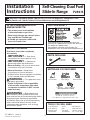
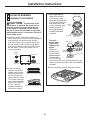
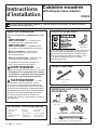
TOOLS YOU WILL NEED
• 1/4” Nut Driver • Level • Pipe Wrench
• Tape Measure • Drill • Safety Glasses
• Phillips Head • Flat Head • Wrench or Pliers
Screwdriver Screwdriver (for 1 7/16” Nut)
1
MATERIALS YOU MAY NEED
31-10641-3 03-09 JR
Printed in the United States
Questions? Call 800.GE.CARES (800.432.2737) or Visit our Website at: GEAppliances.com
In Canada, call 1.800.561.3344 or Visit our Website at: www.GEAppliances.ca
Installation
Self-Cleaning Dual Fuel
Instructions
Slide-In Range
P2S975
BEFORE YOU BEGIN
Read these instructions completely
and carefully.
•
IMPORTANT — Save these
instructions for local inspector’s use.
•
IMPORTANT — Observe all
governing codes and ordinances.
• Note to Installer – Be sure to leave these
instructions with the Consumer.
• Note to Consumer – Keep these
instructions for future reference.
• Product failure due to improper installation
is not covered under the Warranty.
WARNING — This appliance must
be properly grounded.
• Proper installation is the responsibility
of the installer and product failure due
to improper installation is NOT covered
under warranty.
WARNING —
Before beginning
the installation, switch power off at service
panel and lock the service disconnecting means
to prevent power from being switched on
accidentally. When the service disconnecting
means cannot be locked, securely fasten
a prominent warning device, such as a tag,
to the service panel.
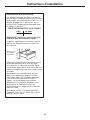
IN THE COMMONWEALTH OF
MASSACHUSETTS:
• This product must be installed by
a licensed plumber or gas fitter.
• When using ball-type gas shut-off valves,
they shall be the T-handle type.
• A flexible gas connector, when used,
must not exceed 3 feet.
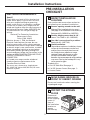
PARTS INCLUDED
Anchor SleevesLag Bolts
(For Concrete Floors Only)
Shut Off Valve
Pipe Fittings
CSA-Approved Flexible Gas Line
3/8″ Min. ID, 1/2″ NPT Connection,
3-foot Maximum Length (Massachusetts only)
Joint Sealant
Screws
Rear Filler
2 Screws
FOR YOUR SAFETY
If you did not receive an anti-tip bracket with your
purchase, call 1.800.626.8774 to receive one at no cost.
(In Canada, call 1.800.561.3344.)
For installation instructions of the bracket, visit:
GEAppliances.com. (In Canada, www.GEAppliances.ca.)
Anti-Tip Bracket
Kit Included

2
Installation Instructions
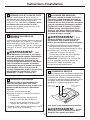
FOR YOUR SAFETY:
WARNING — If the information
in this manual is not followed exactly, a fire,
explosion or gas leak may result causing
property damage, personal injury or death.
Do not store or use gasoline or other
flammable vapors and liquids in the vicinity
of this or any other appliance!
WHAT TO DO IF YOU
SMELL GAS:
• Do not try to light any appliance. Do not
touch any electrical switch; do not use any
phone in your building.
• Immediately call your gas supplier from a
neighbor’s phone. Follow the gas supplier’s
instructions.
• If you cannot reach your gas supplier,
call the fire department.
Installation and service must be performed
by a qualified installer, service agency or
the gas supplier.
IMPORTANT SAFETY INSTRUCTIONS
This range has been design certified by
UNDERWRITERS LABORATORIES for use in
the United States and Canada. You’ll find
safety precautions in your Owner’s Manual.
Read them carefully.
• Installation of this range must conform with
local codes or in the absence of local codes
with the National Fuel Gas Code, ANSI
Z223.1–Latest edition.
• Be sure your range is installed properly by
a qualified installer or service technician.
• To eliminate reaching over surface burners,
cabinet storage above burner should be
avoided.
• Do not install the unit near an outside door
or where a draft may affect its use.
FOR YOUR SAFETY:
WARNING — For personal safety,
remove house fuse or open circuit breaker
before beginning installation. Failure to do so
could result in serious injury or even death.
All rough-in and spacing dimensions must be
met for safe use of your range. Electricity to
the range can be disconnected at the outlet
without moving the range if the outlet is in
the preferred location (remove lower drawer).
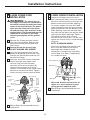
To reduce the risk of burns or fire when
reaching over hot surface elements, cabinet
storage space above the cooktop should be
avoided. If cabinet storage space is to be
provided above the cooktop, the risk can
be reduced by installing a range hood that
protrudes at least 5” beyond the front of the
cabinets. Cabinets installed above a cooktop
must be no deeper than 13”.
Be sure your appliance is properly installed
and grounded by a qualified technician.
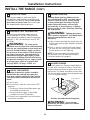
Rating
plate location
ELECTRICAL REQUIREMENTS
This appliance must be supplied with the
proper voltage and frequency and connected
to an individual, properly grounded branch
circuit, protected by a circuit breaker or fuse
having a recommended amperage rating per
the table below.
BREAKER OR FUSE SIZE
240V 40 Amps
208V 40 Amps
NOTE: Check Local Codes for required
breaker size.
Rating plate is located above the storage drawer
below the oven frame.
We recommend you have the electrical wiring
and hookup of your range connected by a
qualified electrician. After installation, have the
electrician show you where your main range
disconnect is located.

3
Installation Instructions
ELECTRICAL REQUIREMENTS-
(cont.)
Check with your local utilities for electrical
codes which apply in your area. Failure to
wire your range according to governing
codes could result in a hazardous condition.
If there are no codes, your range must be
wired and fused to meet the requirements of
the National Electrical Code, ANSI/NFPA No.
70–Latest edition. You can get a copy by
writing:
National Fire Protection Association
Batterymarch Park
Quincy, MA 02269
Effective January 1, 1996, the National
Electrical Code requires that new, but not
existing, construction utilize a four-conductor
connection to an electric range. When installing
an electric range in new construction, a mobile
home, recreational vehicle or an area where
local codes prohibit grounding through the
neutral conductor, follow the instructions in the
section on NEW CONSTRUCTION AND FOUR-
CONDUCTOR BRANCH CIRCUIT
CONNECTION.
In Canada your range must be wired and
fused to meet the requirements of the
Canadian Electrical Code.
You must use a three-wire, single-phase
A.C. 208Y/120 Volt or 240/120 Volt, 60 hertz
electrical system.
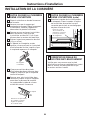
INSPECT INSTALLATION
LOCATION
Refer to alternate construction section for
the following non-standard installations.
Counter opening extends to the wall:
Maintop Filler (supplied with the range.)
(See page 15 for Installation Instructions) or
Backguard (Kit JXS32XX or JXS37XX).
Counter height greater than 36-3/4″:
Lower Trim Slide-In (Kit JXS56XX).
One side is not enclosed by a cabinet:
Bodyside (Kit JXS77XX).
Island Installation:
To provide an optimum installation, the top
surface of the countertop must be level
and flat (lie on the same plane) around
the 3 sides that are adjacent to range
cooktop. Proper adjustments to make
the top flat should be made or gaps
between the countertop and range cooktop
may occur. Forcing the cooktop to fit may
cause excessive gaps.
To obtain Kits:
a. Visit GE Web Site (See page 1)
b. Call GE Answer Center (See page 1)
c. Contact Dealer
D
C
B
A
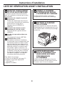
1
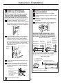
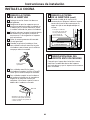
MOVE RANGE INDOORS IN
FRONT OF CABINET OPENING
Do not use hand trucks when moving the
unpackaged range.
2
PROTECT THE KITCHEN
FLOOR
Flatten and
place a piece
of the shipping
carton in
front of
the installation
location to
protect
the flooring.
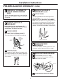
3
ADJUST
PRE-INSTALLATION
CHECKLIST

4
Installation Instructions
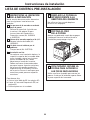
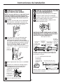
PRE-INSTALLATION CHECKLIST (CONT.)
REMOVE THE DOOR IF
NECESSARY
(cont.)
LIFT OFF DOOR
Lift door up and out until the hinge arms
clear the slots.
DO NOT LIFT THE DOOR BY THE HANDLE.
NOTE: The oven door is very heavy. Be sure
you have a firm grip before lifting the oven
door off the hinges. Use caution once the
door is removed. Do not lay the door on its
handle. This could cause dents or scratches.
5
C
Hinge clears slot
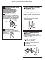
REMOVE THE DOOR IF
NECESSARY
Door removal is not a requirement for
installation of the product, but is an added
convenience. To remove the door:
UNLOCK HINGES
Push both hinge locks down toward the
door frame, to the unlocked position.
This may require a flat blade screwdriver.
POSITION DOOR
Place hands on both sides of the door, and
close the oven door to the removal position.
This is half way between the broil stop and
fully closed.
B
A
5
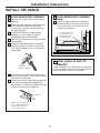
REMOVE PACKING
MATERIALS
Also remove labels on door, plastic on trim
and panel and all tape around the range.
6
REMOVE STORAGE DRAWER
Pull the drawer out until it stops.
Lift the front of the drawer until the
stops clear the guides.
Pull forward and remove the drawer.
C
B
A
7
Rail
Guide
Stop
Stop
Hinge
slot
Hinge
unlocked
position
Hinge
arm
CAREFULLY, TILT RANGE TO
ACCESS RANGE LEVELING
LEGS
Use an adjustable wrench to screw leveling
legs out so that support flanges clear top of
countertop.
4

5
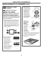
Installation Instructions
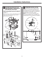
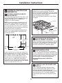
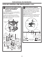
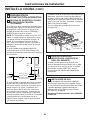
STANDARD INSTALLATION
If the construction of your cabinet cannot
provide a 1/4″ flat area at the back of the
countertop opening, consider changing the
countertop to accommodate this dimension.
See Alternate Construction section.
NOTE: A 1-1/2″ minimum clearance must
be maintained between the rear edge of the
cooktop and the rear wall above the cooktop.
9
PRE-INSTALLATION CUTOUT
AND REQUIRED CLEARANCES
(FOR INDOOR USE ONLY)
If cabinets are placed less than 30″ above the
range, see Alternate Construction, Step 25D,
on page 15.
Wall coverings, counters and cabinets around
range must withstand heat (up to 194°F)
generated by the range.
8
12
″
23-3/16
″
7
″
Acceptable
Gas Line &
Electrical
Outlet Area
30″ Min.
30
″
Min.
from
cooking
surface to bottom
of overhead
cabinets
Shave Raised Edge
To
Clear 31-1/8
″
Wide Control Panel
9-1/2
″
Min.
From Walls
13
″
Max.
depth
For Optimum
Installation These
Surfaces Must
Be Flat & Level
Follow instructions
packaged with
alternate appliance
Countertop
Depth 25
″
(typical)
35-3/4
″
to 36-1/2
″
from floor to
countertop
18
″
Min. vertical
distance from the
bottom of the adjacent
overhead cabinets
1-1/4
″
Min. Counter top
to top of drawer
Drawer
cord, plug,
receptacle box
3.5
″
to prevent
interference
& gas hookup
Max. depth of
with drawer
9/16
″
29-15/16"Min.
30-1/16" Max.
29-15/16
″
Min.
30-1/16
″
Max.
3
″
15
″
1/4″ min.
flat
9/16″
min.
flat
29-15/16″–30-1/16″
smooth cut
23-3/16″
typically
Wall
Flat area
R
1/4″
36″
Front
Floor
Back
25″
typically
9/16″
min.
flat

6
Installation Instructions
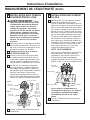
MAKING THE CONNECTIONS
(cont.)
Install 1/2″ flare union adaptor to the 1/2″
NPT elbow on pressure regulator.
Connect flexible appliance connector to
flare union.
Move range into approximate position
and connect flexible connector to gas
supply line with proper flare union
adaptor.
To prevent gas leaks, put a pipe joint
sealant or Teflon
®
tape on all male
threads. NOTE: Make sure sealant or tape
is compatible with Natural and LP gases.
When you are finished making
connections, be sure that all range knobs
are turned to OFF before you open the
main gas supply valve.
WARNING: Do not use a flame
to check for gas leaks. Use liquid leak detector
at all joints and connections to check for leaks
in the system.
I
F
E
10
H
G
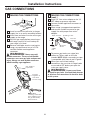
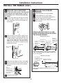
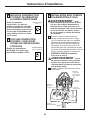
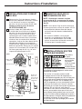
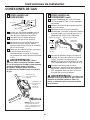
GAS CONNECTIONS
MAKING THE CONNECTIONS
Install a manual shut-off valve in the gas
supply line in an easily accessible location.
Know how and where to shut off the gas
supply to the range.
Shut off gas supply before removing an
old range. Leave it off until hookup of
new range is finished.
Because solid pipe restricts moving the
range, we recommend use of a C.S.A.
certified flexible metal appliance
connector.
WARNING: Never reuse old
flexible connectors. The use of old flexible
connectors can cause gas leaks and personal
injury. Always use new flexible connectors
when installing a gas appliance.
B
A
10
D
C
3″
15″
12″
3
1
⁄2″
7″
Gas Inlet
Gas supply to
top burner
Pressure
regulator as
seen from
front of range
Pressure
regulator
Gas
supply
line
90° street
elbow
Shut-off valve Flexible gas line
7″ Max.
NOTE: When
screwing on the flare
union adaptor, hold
the gas inlet firmly
with a wrench.

7
Installation Instructions
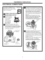
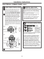
ELECTRICAL CONNECTIONS
The range is shipped with a 4-
wire power cord. If your outlet
looks like the one shown, skip to
step 19 and proceed.
POWER CORD AND STRAIN
RELIEF INSTALLATION
Remove the wire
cover (on the back
of the range) by
removing 2
screws, using a
1/4″ nut driver.
Do not discard
these screws.
Remove the knockout ring (1-3/8″)
located on bracket directly below the
terminal block. To remove the knockout,
use a pair of pliers to bend the knockout
ring away from the bracket and twist
until ring is removed.
B
A
11
For power cord installations only (see the
next step if using conduit), assemble the
strain relief in the hole. Insert the power
cord through the strain relief and tighten.
Allow enough slack to easily attach the
cord terminals to the terminal block. If
tabs are present at the end of the winged
strain relief, they can be removed for
better fit.
NOTE: Do not install the power cord
without a strain relief. The strain relief
bracket should be installed before
reinstalling the rear range wiring cover.
For conduit installations only, purchase
a squeeze connector matching the
diameter of your conduit and assemble
it in the hole. Insert the conduit through
the squeeze connector and tighten. Allow
enough slack to easily attach the wires to
the terminal block.
NOTE: Do not install the conduit without
a squeeze connector. The squeeze
connector should be installed before
reinstalling the rear range wiring cover.
D
C
Wire Cover
Terminal block
(appearance
may vary)
Knockout
ring removed
Knockout ring
in bracket
Terminal
block
Bracket
Terminal
block
Strain relief
Power cord
Bracket
Squeeze
connector
Conduit
NEMA 14-50R
4-wire

8
Installation Instructions
NEW CONSTRUCTION AND
FOUR-CONDUCTOR BRANCH
CIRCUIT
All New Constructions, Mobile
Homes, Recreational Vehicles
and Installations Where Local
Codes Do Not Allow Grounding
Through Neutral Must Use the
4-Wire Cord Provided.
FOR EXISTING
CONSTRUCTION,
A THREE-WIRE FLEXIBLE
CORD KIT MAY BE USED
Follow instructions in step
14 if you require a 3-wire
cord:
13
12
3-WIRE POWER CORD
INSTALLATION
WARNING: The neutral or
ground wire of the power cord must
be connected to the neutral terminal
located in the center of the terminal
block. The power leads must be
connected to the lower left and
the lower right terminals of the
terminal block.
Remove the 3 lower terminal screws
from the terminal block. Insert the 3
terminal screws through each power
cord terminal ring and into the lower
terminals of the terminal block.
Be certain that the center wire
(white/neutral) is connected to the
center lower position of the terminal
block. Tighten screws securely into
the terminal block.
DO NOT remove the ground strap
connection.
WARNING: Before powering
the unit, ensure that the ground strap
is connected to both the terminal block
and to the ground plate.
Skip to Step 18 and proceed with the
installation.
A
14
B
NEMA 14-50R
4-wire
208/240 40 Amp
3-prong cord
Terminal block
(appearance
may vary)
Ground
plate
Power cord
Ground
strap
Neutral
terminal
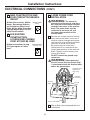
ELECTRICAL CONNECTIONS (CONT.)

9
Installation Instructions
3-WIRE CONDUIT INSTALLATION
Loosen the 3 lower terminal screws
from the terminal block. Insert the center
bare wire (white/neutral) tip through the
bottom center terminal block opening.
On certain models, the wire will need
to be inserted through the ground strap
opening and then into the bottom center
block opening. Insert the two side bare
wire tips into the lower left and the lower
right terminal block openings. Tighten
the screws until the wire is firmly
secured (35 to 50 inch-lbs.). Do not over-
tighten the screws since it could damage
the wires.
NOTE: ALUMINUM WIRING:
Aluminum building wire may be used
but it must be rated for the correct
amperage and voltage to make
connection. Connect wires according
to this Step 16 or Step 17 depending
on number of wires.
Wire used, location and enclosure of
splices, etc., must conform to good
wiring practices and local codes.
Skip to Step 18 and proceed with the
installation.
B
A
16
4-WIRE POWER CORD
INSTALLATION
WARNING: The neutral wire of
the supply circuit must be connected to
the neutral terminal located in the lower
center of the terminal block. The power
leads must be connected to the lower
left and the lower right terminals of the
terminal block. The ground lead must be
connected to the frame of the range
with the ground plate and the ground
screw.
Remove the 3 lower terminal screws
from the terminal block. Remove the
ground screw and ground plate and
retain them.
Cut and discard the ground strap.
DO NOT DISCARD ANY SCREWS.
Insert the one ground screw into the
power cord ground wire terminal ring,
through the ground plate and into the
frame of the range.
Insert the 3 terminal screws (removed
earlier) through each power cord
terminal ring and into the lower
terminals of the terminal block. Be
certain that the center wire (white/
neutral) is connected to the center lower
position of the terminal block. Tighten
screws securely into the terminal block.
Skip to Step 18 and proceed with the
installation.
E
D
C
B
A
15
or
Terminal
block
Ground strap
Ground
strap
Neutral
terminal
Before
After
Terminal
block
Ground
screw
Ground
plate
(grounding
to range)
Bracket
Conduit
Wire tips
Terminal block

ELECTRICAL CONNECTIONS (CONT.)
REINSTALL WIRE COVER
NOTE: When reinstalling the wire cover,
make sure that wires do not become pinched
between the wire cover and the housing.
NOTE: The ground strap must be attached
when using the 3-wire cord.
• Terminations must be either closed loop
terminals or open-end spade lugs.
• On some models, a filter capacitor may
be connected between the black and
ground leads on the junction block.
Do not remove capacitor.
18
4-WIRE CONDUIT INSTALLATION
Loosen the three lower terminal screws
from the terminal block. Remove the
ground screw and ground plate and
retain them. Cut and discard the ground
strap. DO NOT DISCARD ANY SCREWS.
Insert the ground bare wire tip between
the range frame and the ground plate
(removed earlier) and secure it in place
with the ground screw (removed earlier).
Insert the bare wire (white/neutral) tip
through the bottom center of the
terminal block opening. Insert the two
side bare wire tips into the lower left and
the lower right terminal block openings.
Tighten the screws until the wire is firmly
secured (35 to 50 inch-lbs.). Do not over-
tighten the screws since it could damage
the wires.
Proceed to Step 18.
B
C
A
17
or
Terminal
block
Ground strap
Neutral
terminal
Ground strap
Before
Terminal
block
Wire tips
Ground
screw
Bracket
Ground
plate
(grounding
to range)
After
10
Installation Instructions
ANTI-TIP DEVICE INSTALLATION
To reduce
the risk of
tipping the range,
the range must
be secured by a
properly installed
anti-tip bracket.
See installation
instructions shipped with the bracket for complete
details before attempting to install.
To check if the bracket is installed and engaged
properly, remove the storage drawer or kick
panel and look underneath the range to see that
the leveling leg is engaged in the bracket. On
models without a storage drawer or kick panel,
carefully tip the range forward. The bracket
should stop the range within 4 inches. If it does
not, the bracket must be reinstalled. If the range is
pulled from the wall for any reason, always repeat
this procedure to verify the range is properly
secured by the anti-tip bracket. Never completely
remove the leveling legs or the range will not be
secured to the anti-tip device properly.
19

11
Installation Instructions
INSTALL THE RANGE
SLIDE RANGE INTO OPENING
Position the range in front of the cabinet
opening.
Make sure the supports which overhang
the countertop clear the countertop.
If necessary, raise the unit by lowering
the leveling legs.
Push while lifting the range into the
opening, until the range is within 2″
of engaging the anti-tip bracket.
Remove the protective trim from the side
(if provided).
Using the adjustable pliers or wrench,
carefully screw in the back leveling leg
until the overhang comes to rest on the
countertop.
Carefully screw in the front two leveling
legs (similar to Step E) until the overhang
touches the countertop.
Carefully push the range into the opening
until the countertop fully engages the
control panel. The back maintop overhang
should cover the cutout opening.
G
F
E
D
C
B
A
20
SLIDE RANGE INTO OPENING
(cont.)
Plug the range cord into the receptacle.
Locate the cord in the back of the range
in a manner that it will not touch or be
moved by the drawer.
H
20
STORAGE DRAWER
Position range cord
so that there is no
interference with
storage drawer
Adjustable
wrench or pliers
Countertop
Make sure the edge of
the countertop fits flush
against the end of the
front control panel
FINAL CHECK OF ANTI-TIP
BRACKET
Check to make sure that the rear leveling leg
is fully inserted into the Anti-Tip bracket and
that the bracket is securely installed.
21

12
Installation Instructions
INSTALL THE RANGE (CONT.)
REPLACE THE OVEN DOOR
NOTE: The oven door is heavy. You may need
help lifting the door high enough to slide it
into the hinge slots. Do not lift the door by
the handle.
Lift the oven door by placing one hand
on each side. The door is heavy, so you
may need help. Do not lift the door by
the handle.
With the door at the same angle as the
removal position (halfway between the
closed and broil stop position), seat the
notch of the hinge arm into the bottom
edge of the hinge slot. The notch of the
hinge arm must be fully seated into the
bottom of the slot.
Open the oven door as far as it will open.
Push the hinge locks up against the front
frame of the oven cavity, to the locked
position.
Close the oven door.
E
D
C
B
A
22
REPLACE THE STORAGE
DRAWER
Place the drawer rail on the guides.
Push the drawer in until it stops.
Lift the front of the drawer and push in
until the stops clear the guides.
Lower the front of the drawer and push in
until it closes.
SPECIAL INSTRUCTIONS IF YOU ARE
HAVING PROBLEMS WHILE REPLACING
THE STORAGE DRAWER
Remove and replace, making sure the power
cord is not obstructing the drawer and/or the
rail is in the guide.
Remove and replace, making sure the rail is in
the guide.
D
C
B
A
23
Stop
Bottom edge
of slot
Hinge in
locked position
Notch of hinge
securely fitted
into bottom of
hinge slot
Drawer does
not close
completely
Drawer
front panel
tipped away
from body
side
Rear drawer
support is on top
of guide rail on
the high side
Drawer front panel
tipped to one side
Hinge arm
Hinge notch
If Drawer Won’t Close:
If Drawer is Crooked:
Power cord
may be
obstructing
drawer
in this area
Rear drawer
support is
resting on top
of guide rail

13
Installation Instructions
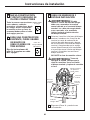
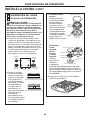
c.
Front right burner
Make sure the hole
in the burner head
assembly is positioned
over the electrode and
that the burner head
is fully inserted inside
the burner base. A
small gap between
the base and head
is normal.
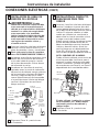
Front left
burner, back
right burner
and back left
burner
Make sure
the slot in the
burner head is
positioned over
the electrode.
The burner cap
has three to four pins. When placing the cap,
make sure none of the pins sits in the stability
chamber.
d.Place the burner grates over the burners.
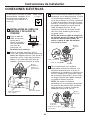
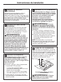
COOKTOP BURNERS
ASSEMBLE THE BURNERS
CAUTION: The electrode of the
spark igniter is exposed. Be careful not to
push any cooktop controls while the top
of the burner is removed. Do not remove
the top or touch the electrode of any burner
while another burner is turned on. Electrical
shock might result.
a. Place the burner head onto the burner
base, making sure that the head is properly
oriented over the burner base and the
electrode. Make sure to place the correct
burner head on the correct burner base
and that the burner head sits level on the
burner base. The burner heads are not
interchangeable.
b.Place the burner
caps on the burner
heads, making sure
to place the correct
burner cap on the
correct burner head.
The burner caps are
not interchangeable.
Make sure that the
burner caps are
properly seated on
the burner heads.
A
24
Burner cap
Burner head
Burner base
Electrode
Burner cap
Burner
head
Burner base
Electrode
Stability
chamber
Burner cap not properly seated
Burner cap properly seated
Medium
head
Front of range
Large head
Small head
Extra large head

INSTALL THE RANGE (CONT.)
14
Installation Instructions
CHECK THE IGNITERS
Operation of the electric igniters should be
checked after the cooktop and supply line
have been carefully checked for leaks and the
cooktop has been connected to the electrical
power.
a. Turn on gas.
b. Push and turn a burner valve to the LITE
position.
• The burner valve should light when gas
is available to the burner.
• Once the burner lights, it should be
turned out of the LITE position.
c. Try each valve separately until all burners
have been checked.
D
BURNER IGNITION
Cooktop Spark Ignition—When you turn
the cooktop knob to LITE, the spark igniter
makes a series of electric sparks (ticking
sounds) which light the burner. During a
power failure the burners will not light
automatically. In an emergency, a cooktop
burner may be lit with a match by following
the steps below.
WARNING: Lighting gas burners
with a match is dangerous. You should match
light the cooktop burners only in an
emergency.
a. Light a match and hold the flame near the
burner you want to light. Wooden matches
work best.
b. Push in and turn the control knob slowly.
Be sure you are turning the correct knob
for the burner you are lighting.
NOTE: If the burner does not light within
five seconds, turn the knob off and wait
5 minutes before trying again.
E
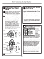
BURNER FLAMES
Turn each burner on. Flames should be blue
in color with no trace of yellow. The burner
flames should not flutter or blow away from
the burner. The flame should be no less than
1/4″ on the lowest setting and no greater than
1-1/2″ on highest setting.
Burners should be checked frequently
WARNING: If you attempt
to measure the flame, please use caution.
Burns could result.
F
CHECK FOR LEAKS
Turn the gas supply on and use a liquid
leak detector (soap solution) at all joints and
connections to check for leaks. Do not use an
open flame to look for leaks. Be sure all leaks
are stopped before lighting burners.
B
PRESSURE TEST INFORMATION
The maximum allowable supply pressure
for the regulator is 14″ W.C. The minimum
supply pressure needed to check the regulator
setting is 7″ W.C. for natural gas and 10″ W.C.
for LP gas.
WARNING: The range and its
individual shut-off valve must be disconnected
from the gas supply piping system during any
pressure testing of the gas supply system at
test pressures of more than 1/2 psig (pounds
per square inch gauge). The range must be
isolated from the gas supply piping system
by closing its individual shut-off valve during
any pressure testing of the gas supply system
at test pressures equal to or greater than
1/2 psig. NOTE: 1/2 psig = 13.855″ w.c.
C
Cooktop Burner
1/4″ to
1-1/2″

15
Installation Instructions
ALTERNATE CONSTRUCTION
PREPARATION
OPTIONAL MAINTOP FILLER OR
BACKGUARD KIT
If counter opening extends to the wall, it will
require Maintop Filler Kit (supplied with the
range) or Backguard Kit (JXS32XX or
JXS37XX) to close the gap.
NOTE: If the countertop is greater than 25″,
it will show a gap between the backguard
and wall or between filler kit and the wall.
If the countertop is less than 25″, a gap will
occur between the countertop front and the
control panel ends (see Step 8).
If you are using the optional backguard kit,
refer to the backguard kit instructions for
installation details.
If you use the filler kit, place the metal filler
piece supplied with the range to the back of
the range as shown in the figure below. Start
the 2 screws into the upper holes at the
outside rear of the range and through the
slots in the trim, holding the filler piece
centered on the maintop frame and pushing
upward to close the gap between the bottom
of the maintop and the filler trim.
A
25
When the trim is set in the proper position,
tighten the 2 mounting screws. The top of
the trim should be located below the top surface
of the maintop to prevent pots, pans and skillets
from damaging the painted parts.
Refer to the Standard Installation of the Range
on page 5.
Wall
25″
Must be
level
Must be
flat
30″
smooth cut
Must be level
31-1/8″
Must
be
flat
(2) #8
screws
Maintop filler
Range
Cooktop
FOR NON-BUILT-IN INSTALLATION
(END OF CABINET LOCATION)
When installing the range at the end of a cabinet
section which will expose the unfinished side of
the range, use Body Side Kit (JXS77XX). Refer
to the kit instructions or installation details.
B
ISLAND INSTALLATION
Attach the anti-tip bracket per the instructions
that are supplied with the bracket. Be aware that
the screws provided are long and may penetrate
though the back of the island cabinets. Follow
the instructions included with the bracket.
Do not use Backguard Kit JXS32XX or
JXS37XX.
C
CABINETS OVER THE RANGE LESS
THAN 30″
If a 30″ clearance between cooking surface
and overhead combustible material or metal
cabinets cannot be maintained, protect
the underside of the cabinets above the cooktop
with not less than 1/4″ insulating millboard
covered with sheet metal not less than 0.0122″
thick.
D

INSTALL THE RANGE (CONT.)
16
Installation Instructions
Please see L.P. conversion instructions
supplied with this range when L.P. Gas
is used.
NOTE: Instructions are mounted on
regulator bracket.
OPERATION CHECKLIST
• Double check to make sure everything in
this guide has been completed. Rechecking
steps will ensure safe use of the cooktop.
• Make sure all controls are left in the OFF
position.
• Make sure the flow of combustion
and ventilation air to the cooktop is
unobstructed.
• The serial plate for your Range is located
under the oven door above the storage
area. In addition to the model and serial
numbers, it tells you the ratings of the
burners and the type of fuel and pressure
the cooktop was adjusted for when it left
the factory.
• When ordering parts, always include the
serial number and model number to ensure
proper replacement parts.
• Recheck Steps: Double check to make
sure everything in this guide has been
completed. Rechecking steps will ensure
safe use of the Range.
26

17
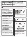
MATÉRIAUX DONT VOUS POUVEZ
AVOIR BESOIN
Si vous avez des questions, appelez le 1.800.561.3344 ou visitez notre site Web à l’adresse :
www.electromenagersge.ca
Instructions
Cuisinière encastrée
d’installation
autonettoyante à deux carburants
P2S975
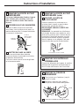
AVANT DE COMMENCER
Lisez ces instructions complètement et avec
soin.
•
IMPORTANT — Conservez ces
instructions pour l’inspecteur local.
•
IMPORTANT — Respectez tous
les codes et les ordonnances en vigueur.
• Note à l’installateur : Assurez-vous
de donner toutes ces instructions
au consommateur.
• Note au consommateur : Conservez ces
instructions pour référence future.
• La garantie ne couvre aucune panne
due à une mauvaise installation.
AVERTISSEMENT — Cet
appareil ménager doit être bien mis à la terre.
• L’installateur est responsable d’une bonne
installation et la garantie ne couvre aucune
panne due à une mauvaise installation.
AVERTISSEMENT —
Avant
de commencer votre installation, coupez
le courant au niveau du panneau de service
et verrouillez le mécanisme de sectionnement
de courant afin d'empêcher toute alimentation
accidentelle de courant. Si vous ne pouvez pas
verrouiller le mécanisme de sectionnement
de courant, attachez bien en évidence au
panneau de service un avertissement, comme
une étiquette.
PIÈCES COMPRISES
Manchons d’ancrage
Tire-fonds
(pour planchers en ciment seulement)
Robinet d’arrêt
Raccords de tuyaux
Raccord flexible de gaz approuvé par l’ACNOR
DI min 3/8 po, Jonction NPT 1/2 po
Produit d’obturation
des joints
Vis
Entretoise arrière
2 vis
31-10641-3 03-09 JR
POUR VOTRE SÉCURITÉ
Si vous n'avez pas reçu de soutien anti-basculement avec
votre achat, appelez le 1.800.626.8774 pour le recevoir
gratuitement (au Canada, appelez le 1.800.561.3344).
Pour les instructions d'installation du soutien, visitez
le site Internet GEAppliances.com (au Canada,
www.GEAppliances.ca).
Anti-Tip Bracket
Kit Included
OUTILS DONT VOUS AUREZ BESOIN
• Tourne-écrou • Niveau • Clé à tube
de 1/4 po
• Lunettes • Perceuse
• Mètre de sécurité
• Clé ou tenailles
• Tournevis à tête • Tournevis (pour un écrou
Phillips à lame plate de 1-7/16 po)

18
Instructions d’installation
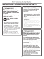
POUR VOTRE SÉCURITÉ :
AVERTISSEMENT —
Si vous ne suivez pas exactement les
renseignements contenus dans ce manuel, vous
pouvez occasionner un incendie, une explosion ou
une fuite de gaz qui peut causer des dommages
matériels, des blessures corporelles ou la mort.
Ne conservez ou n’usez jamais d’essence
ou d’autre liquide ou vapeur inflammable
à proximité de cet appareil ou de tout autre
appareil ménager!
QUE FAIRE SI VOUS
SENTEZ LE GAZ :
• N’essayez jamais d’allumer un appareil ménager.
Ne touchez aucun commutateur électrique;
n’utilisez aucun téléphone dans votre bâtiment.
• Appelez immédiatement votre fournisseur
de gaz en utilisant le téléphone d’un voisin.
Suivez les instructions du fournisseur de gaz.
• Si vous n’arrivez pas à communiquer avec
votre fournisseur de gaz, appelez les pompiers.
L’installation et le service doivent être faits par
un installateur qualifié, une agence de service
ou votre fournisseur de gaz.
CONSEILS DE SÉCURITÉ IMPORTANTS
POUR VOTRE SÉCURITÉ :
AVERTISSEMENT — Pour votre
sécurité personnelle, enlevez le fusible de votre
maison ou débranchez le disjoncteur de courant
avant de commencer votre installation. Si vous
ne le faites pas, vous pouvez occasionner
des blessures sérieuses ou même la mort.
Vous devez respecter toutes les dimensions
d’espacement libre pour utiliser votre cuisinière
en toute sécurité. Vous pouvez débrancher
l’électricité de votre cuisinière à la prise sans
bouger la cuisinière si la prise se trouve dans
sa position préférée (enlevez le tiroir du bas).
Pour réduire le risque de brûlures ou d’incendie
quand vous vous penchez sur des éléments
de surface chauds, vous devez éviter de placer
une armoire de rangement au-dessus de la table
de cuisson. Si vous devez placer une armoire
de rangement au-dessus de la table de cuisson,
vous pouvez réduire ce risque en installant
une hotte de ventilation qui avance au moins
de 12,7 cm (5 po) par rapport à l’avant de
l’armoire. Les armoires installées au-dessus
d’une table de cuisson ne peuvent dépasser
33 cm (13 po) de largeur.
Assurez-vous que votre appareil soit bien installé
et mis à la terre par un technicien qualifié.
La conception de cette cuisinière a
été certifiée par les UNDERWRITERS
LABORATORIES du Canada. Vous trouverez
des précautions de sécurité dans votre Manuel
du propriétaire. Lisez-les avec soin.
• L’installation de cette cuisinière doit
se conformer aux codes locaux ou, en l’absence
de codes locaux, au National Fuel Gas Code,
ANSI Z223.1—Dernière édition.
• Assurez-vous que votre cuisinière soit bien
installée par un installateur qualifié ou un
technicien du service.
• Pour éviter de vous pencher sur les brûleurs de
surface, vous devez éviter de placer au-dessus
des brûleurs une armoire de rangement.
• N’installez jamais votre appareil près d’une porte
donnant sur l’extérieur ou dans tout endroit où
un courant d’air peut gêner son usage.

19
Instructions d’installation
EXIGENCES ÉLECTRIQUES
Cet appareil ménager doit être livré avec le
bon voltage et la bonne fréquence et branché
à son propre circuit de dérivation bien mis à
la terre, protégé par un disjoncteur ou un
fusible ayant l’ampérage recommandé dans
le tableau ci-dessous.
TAILLE DE DISJONCTEUR OU DE FUSIBLE
240V 40 Amps
208V 40 Amps
REMARQUE : Vérifiez les codes locaux pour
trouver la taille de disjoncteur requise.
La plaque signalétique est située au dessus
du tiroir de rangement sous le châssis de
la cuisinière.
Nous vous recommandons de faire brancher
le câblage électrique et la fiche de votre
cuisinière par un électricien qualifié. Après
l’installation, demandez à l’électricien de vous
montrer l’emplacement de votre coupe-circuit
principal.
Demandez à votre entreprise de services
publics les codes électriques en vigueur
dans votre région. En ne câblant pas votre
cuisinière conformément aux codes en
vigueur, vous provoquez une situation
dangereuse. En l’absence de codes, vous
devez câbler et isoler votre cuisinière
conformément aux exigences du Canadian
Electrical Code.
Vous devez utiliser un système électrique
uniphasé, à trois fils A.C. 208Y/120 volts ou
240/120 volts, 60 Hertz.
Emplacement
de la plaque
signalétique

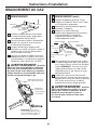
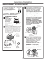
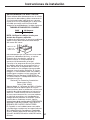
PROTÉGEZ LE PLANCHER
DE LA CUISINE
Aplatissez et placez un morceau de carton
d’emballage devant l’emplacement où vous
allez installer votre cuisinière pour protéger
le plancher.
3
20
Instructions d’installation
INSPECTEZ L’EMPLACEMENT
OÙ VOUS ALLEZ INSTALLER
Consultez la section d’autre construction
pour les installations suivantes qui ne sont
pas normales.
L’ouverture du comptoir se poursuit
jusqu’au mur :
Trousse de remplissage (fournie avec
la cuisinière) (consultez les installations
d’instruction à la page 32) ou
Dosseret (trousse JXS32XX ou
JXS37XX).
La hauteur du compteur est plus
grande que 93,4 cm (36-3/4 po):
Garniture du bas à glisser (trousse
JXS56XX).
Un côté n’est pas enfermé dans une
armoire :
Côté d’appareil (trousse JXS77XX).
Installation dans un îlot :
Pour obtenir une bonne installation,
la surface du haut du comptoir doit être
horizontale et plate (au même niveau)
des trois côtés qui sont adjacents à la
table de cuisson de la cuisinière. Vous
devez bien ajuster la surface du haut
afin de bien l’aplatir, autrement il se
produira des écarts entre le comptoir et
la table de cuisson de votre cuisinière.
En poussant la table de cuisson pour
aller dans le comptoir, vous pouvez
occasionner des écarts excessifs.
Pour obtenir les trousses :
a. Visitez le site Web GE (voir page 17)
b. Appelez le centre de réponse GE
(voir page 17)
c. Appelez le vendeur
D
C
B
A
1
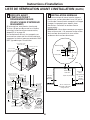
LISTE DE VÉRIFICATION AVANT L’INSTALLATION
AMENEZ LA CUISINIÈRE
À L’INTÉRIEUR EN FACE DE
L’OUVERTURE DE L’ARMOIRE
N’utilisez pas de chariot à main pour
transporter la cuisinière sans emballage.
2
FAITES BASCULER AVEC
SOIN LA CUISINIÈRE POUR
AVOIR ACCÈS AUX PIEDS
D’INCLINAISON DE
LA CUISINIÈRE
Utilisez une clé ajustable pour visser les
pieds d’inclinaison afin de mettre à niveau
le soutien avec le haut du comptoir.
4
AJUSTEZ
La page est en cours de chargement...
La page est en cours de chargement...
La page est en cours de chargement...
La page est en cours de chargement...
La page est en cours de chargement...
La page est en cours de chargement...
La page est en cours de chargement...
La page est en cours de chargement...
La page est en cours de chargement...
La page est en cours de chargement...
La page est en cours de chargement...
La page est en cours de chargement...
La page est en cours de chargement...
La page est en cours de chargement...
La page est en cours de chargement...
La page est en cours de chargement...
La page est en cours de chargement...
La page est en cours de chargement...
La page est en cours de chargement...
La page est en cours de chargement...
La page est en cours de chargement...
La page est en cours de chargement...
La page est en cours de chargement...
La page est en cours de chargement...
La page est en cours de chargement...
La page est en cours de chargement...
La page est en cours de chargement...
La page est en cours de chargement...
La page est en cours de chargement...
La page est en cours de chargement...
La page est en cours de chargement...
La page est en cours de chargement...
-
 1
1
-
 2
2
-
 3
3
-
 4
4
-
 5
5
-
 6
6
-
 7
7
-
 8
8
-
 9
9
-
 10
10
-
 11
11
-
 12
12
-
 13
13
-
 14
14
-
 15
15
-
 16
16
-
 17
17
-
 18
18
-
 19
19
-
 20
20
-
 21
21
-
 22
22
-
 23
23
-
 24
24
-
 25
25
-
 26
26
-
 27
27
-
 28
28
-
 29
29
-
 30
30
-
 31
31
-
 32
32
-
 33
33
-
 34
34
-
 35
35
-
 36
36
-
 37
37
-
 38
38
-
 39
39
-
 40
40
-
 41
41
-
 42
42
-
 43
43
-
 44
44
-
 45
45
-
 46
46
-
 47
47
-
 48
48
-
 49
49
-
 50
50
-
 51
51
-
 52
52


GE P2S975SEPSS Mode d'emploi
- Taper
- Mode d'emploi
- Ce manuel convient également à
dans d''autres langues
Documents connexes
Autres documents
-
KitchenAid KDSS907SSS05 Guide d'installation
-
-
Jenn-Air JGS8750 Manuel utilisateur
-
JennAir JDS1450FP Guide d'installation
-
-
Jenn-Air KSDB900ESS Guide d'installation
-
Legrand Plastic Trim Ring -Instructions Guide d'installation