KitchenAid 30″ & 36″ Wall-Mount Canopy Range Hood Manuel utilisateur
- Catégorie
- Hottes
- Taper
- Manuel utilisateur

30" (76.2 CM) AND 36" (91.4 CM)
WALL-MOUNT CANOPY RANGE HOOD
Installation Instructions and Use & Care Guide
For questions about features, operation/performance, parts, accessories or service, call: 1-800-422-1230
or visit our website at www.kitchenaid.com
In Canada, for assistance, installation and service, call: 1-800-807-6777
or visit our website at www.kitchenaid.ca
HOTTE D'EXTRACTION À MONTAGE MURAL
DE 30" (76,2 CM) ET 36" (91,4 CM)
Instructions d’installation et Guide d’utilisation et d’entretien
Au Canada, pour assistance, installation ou service, composez le 1-800-807-6777
ou visitez notre site web à www.kitchenaid.ca
Table of Contents/Table des matières.............................................................................2
IMPORTANT: READ AND SAVE THESE INSTRUCTIONS.
FOR RESIDENTIAL USE ONLY.
IMPORTANT : LIRE ET CONSERVER CES INSTRUCTIONS.
POUR UTILISATION RÉSIDENTIELLE UNIQUEMENT.
LI315E/W10674118G

2
TABLE OF CONTENTS
RANGE HOOD SAFETY .................................................................3
INSTALLATION REQUIREMENTS ................................................5
Tools and Parts ............................................................................5
Location Requirements................................................................5
Venting Requirements..................................................................6
Electrical Requirements ...............................................................7
INSTALLATION INSTRUCTIONS ..................................................8
Prepare Location..........................................................................8
Install Range Hood.......................................................................9
Connect Vent System ..................................................................9
Make Electrical Connection .......................................................10
Install Vent Covers .....................................................................11
Complete Installation .................................................................11
RANGE HOOD USE......................................................................11
Controls and Features................................................................11
RANGE HOOD CARE ...................................................................12
Cleaning......................................................................................12
WIRING DIAGRAM ......................................................................14
ASSISTANCE OR SERVICE.........................................................15
In the U.S.A. ...............................................................................15
In Canada ...................................................................................15
Accessories................................................................................15
WARRANTY ..................................................................................16
TABLE DES MATIÈRES
SÉCURITÉ DE LA HOTTE DE CUISINIÈRE................................17
EXIGENCES D’INSTALLATION...................................................19
Outils et pièces...........................................................................19
Exigences d’emplacement.........................................................19
Exigences concernant l’évacuation ...........................................20
Spécifications électriques ..........................................................21
INSTRUCTIONS D’INSTALLATION.............................................22
Préparation de l’emplacement...................................................22
Installation de la hotte ................................................................23
Raccordement du circuit d’évacuation......................................23
Raccordement électrique...........................................................24
Installation des cache-conduits .................................................25
Achever l’installation ..................................................................25
UTILISATION DE LA HOTTE .......................................................26
Commandes et caractéristiques................................................26
ENTRETIEN DE LA HOTTE..........................................................27
Nettoyage ...................................................................................27
SCHÉMA DE CÂBLAGE ..............................................................29
ASSISTANCE OU SERVICE.........................................................30
Au Canada..................................................................................30
Accessoires ................................................................................30
GARANTIE.....................................................................................31

3
RANGE HOOD SAFETY
You can be killed or seriously injured if you don't immediately
You
can be killed or seriously injured if you don't
follow
All safety messages will tell you what the potential hazard is, tell you how to reduce the chance of injury, and tell you what can
happen if the instructions are not followed.
Your safety and the safety of others are very important.
We have provided many important safety messages in this manual and on your appliance. Always read and obey all safety
messages.
This is the safety alert symbol.
This symbol alerts you to potential hazards that can kill or hurt you and others.
All safety messages will follow the safety alert symbol and either the word “DANGER” or “WARNING.”
These words mean:
follow instructions.
instructions.
DANGER
WARNING
State of California Proposition 65 Warnings:
WARNING: This product contains one or more chemicals known to the State of California to cause cancer.
WARNING: This product contains one or more chemicals known to the State of California to cause birth defects or other
reproductive harm.

4
IMPORTANT SAFETY INSTRUCTIONS
READ AND SAVE THESE INSTRUCTIONS

5
INSTALLATION REQUIREMENTS
Tools and Parts
Gather the required tools and parts before starting installation.
Read and follow the instructions provided with any tools listed here.
Tools Needed
■ Level
■
Drill with 1¼" (3.0 cm),
³⁄₈
" (9.5 mm), and
⁵⁄₁₆
" (7.9 mm) drill bits
■ Pencil
■ Wire stripper or utility knife
■ Tape measure or ruler
■ Pliers
■ Caulking gun and weatherproof caulking compound
■ Vent clamps
■ Jigsaw or keyhole saw
■ Flat-blade screwdriver
■ Metal snips
■ Phillips screwdriver
Parts Needed
■ Home power supply cable
■ ½" (12.7 mm) UL listed or CSA approved strain relief
■ UL listed wire connectors (3)
For Vented Installations, You Will Also Need:
■ 1 wall or roof cap
■ Metal vent system
For Non-Vented (Recirculating) Installations, You Will Also
Need:
■ Recirculation Kit Part Number W10692908 for non-vented
(recirculating) installations only. See “Assistance or Service”
section to order.
■ 6" (15.2 cm) diameter round metal vent duct - length required
is determined by ceiling height.
Parts Supplied
Remove parts from packages. Check that all parts are included.
■ Hood canopy assembly with ventilator and LED and halogen
lights installed
■ Vent transition with back draft dampers installed
■ Metal grease filter(s)—depending on model and size
■ Vent cover support bracket
■ Mounting template
■ 2-piece vent cover
■ 4.2 x 8 screws (4)
■ 5 x 45 mm mounting screws (6)
■ D6.4 x 18 mm washers (2)
■ 8 x 40 mm wall anchors (2)
■ 10 x 60 mm wall anchors (4)
■ 5.4 x 75 mm screws (for 10 x 60 mm wall anchors) (4)
■ 3.5 x 9.5 mm sheet metal screws (2)
■ T10 TORX
®†
adapter
Location Requirements
IMPORTANT: Observe all governing codes and ordinances.
Have a qualified technician install the range hood. It is the
installer's responsibility to comply with installation clearances
specified on the model/serial/rating plate. The model/serial/rating
plate is located behind the left filter on the rear wall of the vent
hood.
Canopy hood location should be away from strong draft
areas, such as windows, doors and strong heating vents.
Cabinet opening dimensions that are shown must be used.
Given dimensions provide minimum clearance.
This range hood is recommended for use with cooktops
with a maximum total rating of 65,000 BTUs or less.
Grounded electrical outlet is required. See “Electrical
Requirements” section.
The canopy hood is factory-set for venting through the roof or
wall. For non-vented (recirculating) installation see “For non-
vented (recirculating) installation only” in the “Connect Vent
System” section. Recirculation Kit Part Number W10692908
is available from your dealer or an authorized parts distributor.
All openings in ceiling and wall where canopy hood will be
installed must be sealed.
For Mobile Home Installations
The installation of this range hood must conform to the
Manufactured Home Construction Safety Standards, Title 24
CFR, Part 328 (formerly the Federal Standard for Mobile Home
Construction and Safety, Title 24, HUD, Part 280) or when such
standard is not applicable, the standard for Manufactured Home
Installation 1982 (Manufactured Home Sites, Communities and
Setups) ANSI A225.1/NFPA 501A, or latest edition, or with local
codes.
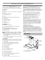
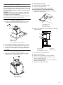
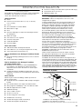
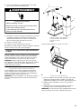
Product Dimensions
*For non-vented (recirculating) installations
**For vented installations
†®TORX is a registered trademark of Acument Intellectual Properties, LLC.
10¾" (27.3 cm)
13³⁄₁₆" (33.5 cm)
*28⁵⁄₁₆" (71.9 cm) min.
42⁵⁄₈" (108.3 cm) max.
**24⁵⁄₈" (62.5 cm) min.
38¾" (98.4 cm) max.
24"
(60.8 cm)
5"
(12.7 cm)
19¹¹⁄₁₆" (50.0 cm)
30" (76.2 cm)
36" (91.4 cm)

6
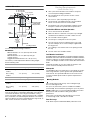
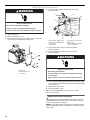
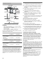
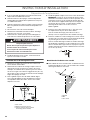
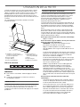
Cabinet Dimensions
*For non-vented (recirculating) installations
IMPORTANT:
Minimum distance “X”: 24" (61.0 cm) from electric
cooking surface.
Minimum distance “X”: 27" (68.6 cm) from gas
cooking surfaces.
Suggested maximum distance “X”: 36" (91.4 cm)
The chimneys can be adjusted for different ceiling heights.
See the following chart.
NOTE: The range hood chimneys are adjustable and designed to
meet varying ceiling or soffit heights depending on the distance
“X” between the bottom of the range hood and the cooking
surface. For higher ceilings, a Chimney Extension Kit is available
from your dealer or an authorized parts distributor. The chimney
extension replaces the chimney shipped with the range hood. To
order, see the “Assistance or Service” section.
Venting Requirements
(Vented Models Only)
■ Vent system must terminate to the outdoors except for
non-vented (recirculating) installations.
■ Do not terminate the vent system in an attic or other
enclosed area.
■ Do not use 4" (10.2 cm) laundry-type wall caps.
■ Use metal vent only. Rigid metal vent is recommended.
Plastic or metal foil vent is not recommended.
■ The length of vent system and number of elbows should
be kept to a minimum to provide efficient performance.
For the Most Efficient and Quiet Operation:
■ Use no more than three 90° elbows.
■ Make sure there is a minimum of 24" (61.0 cm) of straight
vent between the elbows if more than 1 elbow is used.
■ Do not install 2 elbows together.
■ Use clamps to seal all joints in the vent system.
■ The vent system must have a damper. If the roof or wall
cap has a damper, do not use the damper supplied with
the range hood.
■ Use caulking to seal exterior wall or roof opening around
the cap.
■ The size of the vent should be uniform.
Cold Weather Installations
An additional back draft damper should be installed to minimize
backward cold air flow and a thermal break should be installed to
minimize conduction of outside temperatures as part of the vent
system. The damper should be on the cold air side of the thermal
break.
The break should be as close as possible to where the vent
system enters the heated portion of the house.
Makeup Air
Local building codes may require the use of makeup air systems
when using ventilation systems greater than specified CFM of
air movement. The specified CFM varies from locale to locale.
Consult your HVAC professional for specific requirements in
your area.
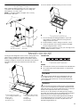
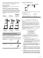
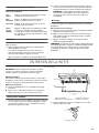
Venting Methods
This canopy range hood is factory set for venting through
the roof or through the wall.
A 6" (15.2 cm) round vent system is needed for installation
(not included). The hood exhaust opening is 6" (15.2 cm) round.
NOTE: Flexible vent is not recommended. Flexible vent creates
back pressure and air turbulence that greatly reduce
performance.
Vent system can terminate either through the roof or wall.
To vent through a wall, a 90° elbow is needed.
Rear Discharge
A 90° elbow may be installed immediately above the hood.
Vented Installations
Min. ceiling height Max. ceiling height
Electric cooking
surface
7' 1" (2.16 m) 9' 2" (2.79 m)
Gas cooking
surface
7' 4" (2.23 m) 9' 2" (2.79 m)
Non-vented (recirculating) Installations
Min. ceiling height Max. ceiling height
Electric cooking
surface
7' 1" (2.16 m) 9' 6" (2.9 m)
Gas cooking
surface
7' 4" (2.23 m) 9' 6" (2.9 m)
10" (25.4 cm) min.
13" (33.0 cm) max.
2" (5.1 cm) min.
9" (22.9 cm) min.*
Centerline
Side
cabinet
Side
cabinet
Vent and power
supply cable
entry location
17" (43.2 cm)*
30" (76.2 cm) or
36" (91.4 cm)
“X”
bottom of
canopy
to cooking
surface
10" (25.4 cm) min.
13" (33.0 cm) max.
Cooking surface

7
For Non-Vented (Recirculating) Installations
If it is not possible to vent cooking fumes and vapors to the
outside, the hood can be used in the non-vented (recirculating)
version, using a Recirculation Kit (which includes charcoal filters
and a deflector). To order, see the “Assistance or Service”
section.
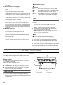
Calculating Vent System Length
To calculate the length of the system you need, add the
equivalent feet (meters) for each vent piece used in the system.
Maximum equivalent vent length is 35 ft (10.7 m).
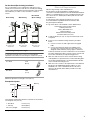
Example Vent System
The following example falls within the maximum recommended
vent length of 35 ft (10.7 m).
Electrical Requirements
Observe all governing codes and ordinances.
Ensure that the electrical installation is adequate and in
conformance with National Electrical Code, ANSI/NFPA 70 (latest
edition), or CSA Standards C22.1-94, Canadian Electrical Code,
Part 1 and C22.2 No. 0-M91 (latest edition) and all local codes
and ordinances.
If codes permit and a separate ground wire is used, it is
recommended that a qualified electrician determine that
the ground path is adequate.
A copy of the above code standards can be obtained from:
National Fire Protection Association
1 Batterymarch Park
Quincy, MA 02169-7471
CSA International
8501 East Pleasant Valley Road
Cleveland, OH 44131-5575
■ A 120 volt, 60 Hz., AC only, 15-amp, fused electrical circuit
is required.
■ If the house has aluminum wiring, follow the procedure
below:
1. Connect a section of solid copper wire to the pigtail
leads.
2. Connect the aluminum wiring to the added section
of copper wire using special connectors and/or tools
designed and UL listed for joining copper to aluminum.
Follow the electrical connector manufacturer's recommended
procedure. Aluminum/copper connection must conform with
local codes and industry accepted wiring practices.
■ Wire sizes and connections must conform with the rating
of the appliance as specified on the model/serial/rating plate.
The model/serial/rating plate is located behind the left filter
on the rear wall of the range hood.
■ Wire sizes must conform to the requirements of the National
Electrical Code, ANSI/NFPA 70 (latest edition), or CSA
Standards C22. 1-94, Canadian Electrical Code, Part 1
and C22.2 No. 0-M91 (latest edition) and all local codes
and ordinances.
Roof Venting Wall Venting
Non-Vented
(Recirculating)
A. Roof cap
B. 6" (15.2 cm)
round vent
A. Wall cap
B. 6" (15.2 cm)
round vent
A. Diverter
B. 6" (15.2 cm)
round vent
Vent Piece 6" (15.2 cm) Round
45° elbow 2.5 ft
(0.8 m)
90° elbow 5.0 ft
(1.5 m)
1 - 90° elbow = 5.0 ft (1.5 m)
1 - wall cap = 0.0 ft (0.0 m)
8 ft (2.4 m) straight = 8.0 ft (2.4 m)
Length of system = 13.0 ft (3.9 m)
A
A
B
B
B
A
90 elbow
6 ft (1.8 m)
2 ft
(0.6 m)
Wall cap

8
INSTALLATION INSTRUCTIONS
Prepare Location
■ It is recommended that the vent system be installed before
hood is installed.
■ Before making cutouts, make sure there is proper clearance
within the ceiling or wall for exhaust vent.
■ Check your ceiling height and the hood height maximum
before you select your hood.
1. Disconnect power.
2. Determine which venting method to use: roof, wall, or
non-vented.
3. Select a flat surface for assembling the range hood.
Place covering over that surface.
4. Using 2 or more people, lift range hood onto covered surface.
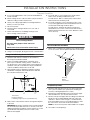
Range Hood Mounting Screws Installation
1. Determine and mark the centerline on the wall where
the canopy hood will be installed.
2. Select a mounting height between a minimum of 24"
(61.0 cm) for an electric cooking surface, a minimum of
27" (68.6 cm) for a gas cooking surface, and a suggested
maximum of 36" (91.4 cm) above the range to the bottom
of the hood. Mark a reference line on the wall.
3. Tape template in place, aligning the template centerline
and bottom of template with hood bottom line and with
the centerline marked on the wall.
4. Mark centers of the fastener locations through the template
to the wall.
IMPORTANT: All canopy mounting screws must be installed
into wood where possible. If there is no wood to screw into,
additional wall framing supports may be required, or use the
(4) 10 x 60 mm wall anchors and 5.4 x 75 mm screws.
Remove the template.
5. For wood, drill ³⁄₁₆" (4.8 mm) pilot holes at all locations
where screws are being installed into wood.
For wall anchors, drill ⁷⁄₁₆" (10 mm) holes at all locations
where wall anchors are being used.
6. For wood, install (2) 5 x 45 mm mounting screws. Leave
a ¹⁄₄" (6.4 mm) gap between the wall and the back of the
screw head to slide range hood into place.
For wall anchors, install the 10 x 60 mm wall anchors
and install the 5.4 x 75 mm screws into the wall anchors.
Tighten until the wall anchors are secure. Back the screws
out ¹⁄₄" (6.4 mm).
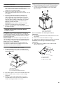
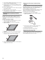
Vent Cover Bracket Installation
7. Attach vent cover bracket to wall flush to the ceiling using (2)
5 x 45 mm screws. Use the optional wall anchors if needed.
Complete Preparation
1. Determine and make all necessary cuts in the wall for the
vent system. Install the vent system before installing the
hood. See “Venting Requirements” section.
2. Determine the required height for the home power supply
cable and drill a 1¼" (3.2 cm) hole at this location.
3. Run the home power supply cable according to the National
Electrical Code or CSA Standards and local codes and
ordinances. There must be enough ½" conduit and wires
from the fused disconnect (or circuit breaker) box to make
the connection in the hood’s electrical terminal box.
NOTE: Do not reconnect power until installation is complete.
4. Use caulk to seal all openings.
A. Centerline
B. Fastener locations
C. Mounting height reference (hood bottom line)
WARNING
Excessive Weight Hazard
Use two or more people to move and install
range hood.
Failure to do so can result in back or other injury.
Vertical Centerline
C
L
LLAW RAER
ETALPMET GNITNUOM
EGDE MOTTOB NGILA
ENIL LICNEP HTIW
MOTTOB GNITACIDNI
DOOH EHT FO
thgieH noitallatsnI
TROPPUS LLAW RAER RO SDUTS HGUORHT SELOH TOLIP "61/3 )OWT( 2 LLIRD
eniL latnoziroH
A
C
B
A. Ceiling
B. Wall
C. Centerline
¹⁄₄"
(6.4 mm)
A
C
B

9
Install In-Line Smart Kit - Optional
NOTE: Your range hood can work with either an internal or an in-
line (external) blower motor system. An optional In-Line Smart Kit
(purchased separately) allows the blower motor that comes with
this range hood to be installed in a location other than inside the
range hood cavity.
CAUTION: To reduce the risk of fire and electric shock, install
this range hood only with the In-Line Smart Kit manufactured
by Whirlpool, part number W10692945.
For installation see the In-Line Smart Kit installation instructions.
See the “Assistance or Service” section to order.
Install Range Hood
1. Using 2 or more people, hang range hood on 2 mounting
screws through the mounting slots on back of hood.
2. Remove the grease filter. See “Range Hood Care” section.
3. Level the range hood and tighten upper mounting screws.
4. Install (2) 5 x 45 mm lower mounting screws and (2) D6.4 x
18 mm washers and tighten. Use the optional wall anchors
if needed.
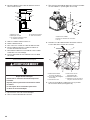
Connect Vent System
1. Install transition on top of hood (if removed for shipping)
with (2) 3.5 x 9.5 mm sheet metal screws.
For Vented Installations Only:
1. Fit vent system over the exhaust outlet.
2. Seal connection with clamps.
3. Check that back draft dampers work properly.
For Non-Vented (Recirculating) Installation Only:
1. Assemble the air deflector with the duct cover bracket
using (4) 4.2 x 8 mm screws.
2. Measure from the bottom of the air deflector to the bottom
of the hood outlet.
3. Cut the duct to the measured size “X.”
4. Remove the air deflector.
5. Slide the duct onto the bottom of the air deflector.
6. Place the assembled air deflector and duct over the
exhaust outlet from the hood.
7. Reassemble the air deflector to the duct cover bracket
with the 4 assembly screws.
8. Seal connections with vent clamps.
A. Mounting screws
B. Mounting slots
C. Lower mounting screws and washers
A. Vent transition
B. 3.5 x 9.5 mm screw
A
B
C
B
A
A. Assembly screws
B. Air deflector
C. Duct cover bracket
A. Air deflector
B. Vent clamp
C. X = length to cut vent duct
D. Vent duct
E. Exhaust outlet
A
B
C
X
A
C
D
B
E

10
Make Electrical Connection
1. Disconnect power.
2. Remove terminal box cover.
3. Remove the knockout in the terminal box cover and install
a UL listed or CSA approved ¹⁄₂" strain relief.
4. Run home power supply cable through strain relief
into terminal box.
5. Use UL listed wire connectors and connect black
wires (C) together.
6. Use UL listed wire connectors and connect white
wires (E) together.
7. Connect green (or bare) ground wire from home power supply
to yellow-green ground wire (F) in terminal box using UL listed
wire connectors.
8. Tighten strain relief screw.
9. Install terminal box cover.
10. Check that all light bulbs are secure in their sockets.
11. Reconnect power.
Optional Power Cord Kit Installations
For optional power cord kit installations, follow the instructions
supplied with the power cord kit. See the “Assistance or Service”
section for information on ordering.
NOTE: Use only with range hood cord connection kits that have
been investigated and found acceptable for use with this model
range hood.
A. Knockout
B. Terminal box cover
C. Screws (7)
WARNING
Electrical Shock Hazard
Disconnect power before servicing.
Replace all parts and panels before operating.
Failure to do so can result in death or electrical shock.
A
B
C
C
C
C
A. Home power supply cable
B. UL listed or CSA approved
strain relief
C. Black wires
D. UL listed wire connectors
E. White wires
F. Green (or bare) and yellow-
green ground wires
A
B
C
D
E
F
WARNING
Electrical Shock Hazard
Electrically ground blower.
Connect ground wire to green and yellow ground wire
in terminal box.
Failure to do so can result in death or electrical shock.

11
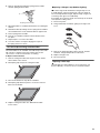
Install Vent Covers
When using both upper and lower vent covers, push lower
cover down onto hood and lift upper cover to ceiling and
install with (2) 4.2 x 8 mm screws.
NOTE: For vented installations the upper vent cover may
be reversed to hide slots.
Secure the bottom of the duct with (2) 4.2 x 8 mm screws.
Complete Installation
1. For non-vented (recirculating) installations only, install
charcoal filters over grille on blower housing. See the
“Range Hood Care” section.
2. Install metal filters. See the “Range Hood Care” section.
3. Check the operation of the range hood blower and light.
See the “Range Hood Use” section.
NOTE: To get the most efficient use from your new range hood,
read the “Range Hood Use” section.
RANGE HOOD USE
The range hood is designed to remove smoke, cooking vapors and
odors from the cooktop area. For best results, start the hood
before cooking and allow it to operate several minutes after the
cooking is complete to clear all smoke and odors from the kitchen.
The range hood controls are located on the front side of the
canopy.
Control Panel
Controls and Features
NOTES:
■ To activate the controls, press and release the desired button.
■ The control feature touch will be lit when a control feature
is turned On.
Sleep Mode
The range hood automatically enters Sleep Mode when not
in use. After 10 minutes of no range hood activity, all of the
control button lights will turn Off. To deactivate Sleep Mode,
press any button.
Auto Sense
Auto Sense allows the range hood fan to turn on automatically
when it senses heat higher than its allowable temperature limit.
When Auto Sense is On, the fan speed will increase or decrease
based on the temperature Auto Sense is measuring.
Auto Sense can be manually increased by pressing a higher
fan speed. The fan will run at the selected speed for 10 minutes
before returning to the speed selected for Auto Sense.
If Auto Sense is On, the Auto button light will turn Off and go
into Sleep Mode when the vent hood is not in use. If the vent
hood is turned On by the consumer or by Auto Sense, the
Auto button light will turn On.
A. Upper vent cover
B. Lower vent cover
C. 4.2 x 8 mm screws
D. Bracket
A
B
C
D
A. Louver holes (non-vented
[recirculating] installations only)
B. Duct covers
C. LED lights (2)
D. Perimetric cover
E. Metal grease filters (located
behind the perimetric cover)
F. Canopy
G. Halogen light
H. Control panel
A
B
C
D
E
F
G
H

12
To Set Auto Sense:
Press AUTO.
To Select Auto Sense Cooktop Type:
NOTE: The range hood is factory-set for the gas cooktop
mode.
Press and hold AUTO for 5 seconds to switch between
the gas cooktop and electric cooktop modes.
The Auto button light will flash 5 times when the range hood
is changed to the electric cooktop mode. Auto Sense is now
set to work with electric cooktops and ranges.
The Auto button light will flash 3 times when the range hood
is changed to the gas cooktop mode. Auto Sense is now set
to work with gas cooktops and ranges.
Changing the cooktop type will change the temperature limit
for Auto Sense to turn On. When the range hood senses
a high enough temperature, the fan will start automatically.
When the temperature drops below the set temperature limit,
the fan will stop automatically. The Auto button light will turn
Off after the range hood enters Sleep Mode, but Auto Sense
is still active.
To Deactivate Auto Sense:
If the Auto button is lit, press AUTO once to deactivate
Auto Sense. The Auto button light will turn Off.
If Auto Sense is in Sleep Mode, press AUTO once to
deactivate Sleep Mode and turn the Auto button light On.
Press AUTO again to deactivate Auto Sense and turn Off
the Auto button light.
Auto Sense will automatically turn off after 2 hours of no
activation of the Auto Sense system. To reset Auto Sense
press AUTO.
Manual Vent Functions
Timer
The range hood can be set to automatically turn Off after
15 minutes.
1. Press and hold the desired fan speed button for 2 seconds.
The fan will run on the chosen speed for 15 minutes,
and the fan speed button light will flash continuously.
After 15 minutes, the fan will turn Off automatically.
2. Press the desired fan speed button again while the fan
timer is running to cancel the fan timer.
NOTE: Changing the fan speed or turning Auto Sense On
will also cancel the 15-minute timer.
Light
The range hood has both task and ambient lighting.
To operate the lights:
1. Touch LIGHT once and the LED task lights will turn On.
2. Touch LIGHT again and the LED task lights will turn Off.
The ambient lights will turn On.
3. Touch LIGHT a third time and the ambient lights will turn Off.
NOTE: To turn both the task and ambient lights On at the same
time, touch and hold LIGHT for 2 seconds. Touch LIGHT again
to turn the task and ambient lights Off.
RANGE HOOD CARE
Cleaning
IMPORTANT: Clean the hood and grease filters frequently
according to the following instructions. Replace grease filters
before operating hood.
Exterior Surfaces:
To avoid damage to the exterior surface, do not use steel wool
or soap-filled scouring pads.
Always wipe dry to avoid water marks.
Cleaning Method:
■ Liquid detergent soap and water, or all-purpose cleanser
■ Wipe with a damp soft cloth or nonabrasive sponge, and
then rinse with clean water and wipe dry.
Metal Grease Filter
1. Open the stainless steel panel. Grasp panel at the front
corners, and then pull down to disengage the 2 catch pins
from the spring catches. The panel is attached at the rear and
will rotate down.
Fan Speeds
Low Press LOW to turn the fan on at Low speed.
Med Press MED to turn the fan on at Medium speed.
Hi Press HI to turn the fan on at High speed.
Boost Press BOOST to turn the fan on at the highest
speed. Boost will automatically turn Off after
10 minutes and the fan will switch to High speed.
A. Metal filters
B. Stainless steel panel
C. Catch pins (2)
D. Spring catches (2)
C
D
A
B

13
2. Remove each filter by pulling the spring release handle
and then pulling down the filter.
3. Wash metal filters as needed in dishwasher or hot detergent
solution.
4. Reinstall the filter by making sure the spring release handles
are toward the front. Insert aluminum filter into upper track.
5. Push in spring release handle.
6. Push up on metal filter, and then release handle to latch
into place.
7. Repeat steps 1 to 5 for the other filter.
8. Close the stainless steel panel. Engage the 2 pins in
the spring catches to secure.
Non-Vented (Recirculating) Installation Filters
The charcoal filter is not washable. It should last up to 6 months
with normal use. Replace with Charcoal Filter Kit. See the
“Accessories” section for information on ordering.
To Replace Charcoal Filter:
1. Remove metal grease filter from range hood. See “Metal
Grease Filter” in this section.
2. Bend spring clips away from metal grease filter.
3. Place charcoal filter into top side of metal filter.
4. Bend spring clips back into place to secure the charcoal
filter to the metal filter.
5. Replace metal grease filter. See “Metal Grease Filter”
in this section.
Replacing a Halogen Lamp (Ambient Lighting)
Turn off the range hood and allow the halogen lamp to cool.
To avoid damage or decreasing the life of the new lamp, do
not touch lamp with bare fingers. Replace lamp, using tissue
or wearing cotton gloves to handle lamp.
If new lights do not operate, make sure the lamps are inserted
correctly before calling service.
1. Disconnect power.
2. Using a flat-blade screwdriver, gently pry the light cover
loose.
3. Remove the lamp and replace with a 120-volt, 40-watt
maximum, halogen lamp made for a G-9 base.
4. Replace the light cover.
5. Reconnect power.
Replacing a LED Lamp
The LED lights are replaceable by a service technician only.
See the “Warranty” section for service contact information.
A. Spring release handle
A

14
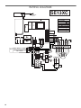
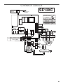
WIRING DIAGRAM
User Interface
Auto - Speed
Sensor
Electronic Power Board
SE13XC
RL3
RL2
RL1
GND
PWM
La2
N
N La1
L
N
C
2
3
1
4
YL
BU
BU
YL
Output: 700mA (2 - 15 VDC)
Driver
+
-
Input: 120 VAC
RD
BK
YL
BU
RD
WH
YL
BK
BU
YL
WH
YL
YL
WH
BK
WH
BK
WH
BK
LED
LED
BK
YL/GN
WH
L1GND N
EMI
Filter
BK
WH
M
YL/GN
BR
YL
WH
RD
BK
GY
BU
1
2
34
56
789
YL/GN
BR
YL
BK
WH
BU
RD
GY
WH
BK
Motor Specifications
Power Supply
Frequency
Power Absorption
Blue - Black
Blue - Gray
Blue - Red
Blue - White
9.8
14.3
18.0
21.6

15
ASSISTANCE OR SERVICE
If you need service
Please refer to the warranty page in this manual.
If you need replacement parts
If you need to order replacement parts, we recommend that
you use only factory specified parts. Factory specified parts
will fit right and work right because they are made with the
same precision used to build every new appliance.
To locate factory specified replacement parts in your area, call
the following customer assistance telephone number or your
nearest designated service center.
In the U.S.A.
Call the KitchenAid Customer eXperience Center toll free:
1-800-422-1230 or visit our website at www.kitchenaid.com.
Our Consultants Provide Assistance With:
■ Scheduling of service. KitchenAid designated service
technicians are trained to fulfill the product warranty and
provide after-warranty service anywhere in the United States.
■ Features and specifications on our full line of appliances.
■ Referrals to local dealers.
■ Installation information.
■ Use and maintenance procedures.
■ Accessory and repair parts sales.
■ Specialized customer assistance (Spanish speaking, hearing
impaired, limited vision, etc.).
For Further Assistance
If you need further assistance, you can write to KitchenAid
with any questions or concerns at:
KitchenAid Brand Home Appliances
Customer eXperience Center
553 Benson Road
Benton Harbor, MI 49022-2692
Please include a daytime phone number in your correspondence.
In Canada
Call the Whirlpool Canada LP Customer eXperience Centre toll
free: 1-800-807-6777 or visit our website at www.kitchenaid.ca.
Our Consultants Provide Assistance With:
■ Scheduling of service. KitchenAid appliances designated
service technicians are trained to fulfill the product warranty
and provide after-warranty service anywhere in Canada.
■ Features and specifications on our full line of appliances.
■ Referrals to local dealers.
■ Use and maintenance procedures.
■ Accessory and repair parts sales.
For Further Assistance
If you need further assistance, you can write to Whirlpool Canada
LP with any questions or concerns at:
Customer eXperience Centre
Whirlpool Canada LP
200 - 6750 Century Ave.
Mississauga, Ontario L5N 0B7
Please include a daytime phone number in your correspondence.
Accessories
Charcoal Filter Kit
(for non-vented installations only)
Order Part Number W10692910
Recirculation Kit
(for non-vented installations only)
Order Part Number W10692908
Chimney Extension Kit
Order Part Number W10272075
Chimney Extension Kit - Black Stainless
(for black stainless vent hood models KVWB600DBS
and KVWB606DBS)
Order Part Number W10750879
6" (15.2 cm) Makeup Air Kit
(consult local building codes)
Order Part Number W10446915
Power Cord Kit
Order Part Number W10613691
In-Line Smart Kit
Order Part Number W10692945

16
11/14
KITCHENAID
®
MAJOR
APPLIANCE LIMITED
WARRANTY
ATTACH YOUR RECEIPT HERE. PROOF OF PURCHASE IS REQUIRED
TO OBTAIN WARRANTY SERVICE.
Please have the following information available when you call the
Customer eXperience Center:
■ Name, address and telephone number
■ Model number and serial number
■ A clear, detailed description of the problem
■ Proof of purchase including dealer or retailer name and address
IF YOU NEED SERVICE:
1. Before contacting us to arrange service, please determine whether your product requires repair. Some
questions can be addressed without service. Please take a few minutes to review the Troubleshooting or
Problem Solver section of the Use and Care Guide, scan the QR code on the right to access additional
resources, or visit http://kitchenaid.custhelp.com.
2. All warranty service is provided exclusively by our authorized KitchenAid Service Providers
. In the U.S. and
Canada, direct all requests for warranty service to:
KitchenAid Customer eXperience Center
In the U.S.A., call 1-800-422-1230. In Canada, call 1-800-807-6777.
If outside the 50 United States or Canada, contact your authorized KitchenAid dealer to determine whether another warranty applies.
http://kitchenaid.custhelp.com
ONE YEAR LIMITED WARRANTY
WHAT IS COVERED WHAT IS NOT COVERED
For one year from the date of purchase, when this
major appliance is installed, operated and maintained
according to instructions attached to or furnished
with the product, KitchenAid brand of Whirlpool
Corporation or Whirlpool Canada LP (hereafter
“KitchenAid”) will pay for Factory Specified
Replacement Parts and repair labor to correct
defects in materials or workmanship that existed
when this major appliance was purchased, or at its
sole discretion replace the product. In the event of
product replacement, your appliance will be
warranted for the remaining term of the original unit's
warranty period.
YOUR SOLE AND EXCLUSIVE REMEDY UNDER
THIS LIMITED WARRANTY SHALL BE PRODUCT
REPAIR AS PROVIDED HEREIN. Service must be
provided by a KitchenAid designated service
company. This limited warranty is valid only in the
United States or Canada and applies only when the
major appliance is used in the country in which it was
purchased. This limited warranty is effective from the
date of original consumer purchase. Proof of original
purchase date is required to obtain service under this
limited warranty.
1. Commercial, non-residential, multiple-family use, or use inconsistent with published
user, operator or installation instructions.
2. In-home instruction on how to use your product.
3. Service to correct improper product maintenance or installation, installation not in
accordance with electrical or plumbing codes or correction of household electrical or
plumbing (i.e. house wiring, fuses or water inlet hoses).
4. Consumable parts (i.e. light bulbs, batteries, air or water filters, preservation solutions,
etc.).
5. Defects or damage caused by the use of non-genuine KitchenAid parts or accessories.
6. Conversion of products from natural gas or L.P. gas.
7. Damage from accident, misuse, abuse, fire, floods, acts of God or use with products
not approved by KitchenAid.
8. Repairs to parts or systems to correct product damage or defects caused by
unauthorized service, alteration or modification of the appliance.
9. Cosmetic damage including scratches, dents, chips, and other damage to the
appliance finishes unless such damage results from defects in materials and
workmanship and is reported to KitchenAid within 30 days.
10. Discoloration, rust or oxidation of surfaces resulting from caustic or corrosive
environments including but not limited to high salt concentrations, high moisture or
humidity or exposure to chemicals.
11. Food or medicine loss due to product failure.
12. Pick-up or delivery. This product is intended for in-home repair.
13. Travel or transportation expenses for service in remote locations where an authorized
KitchenAid servicer is not available.
14. Removal or reinstallation of inaccessible appliances or built-in fixtures (i.e. trim,
decorative panels, flooring, cabinetry, islands, countertops, drywall, etc.) that interfere
with servicing, removal or replacement of the product.
15. Service or parts for appliances with original model/serial numbers removed, altered or
not easily determined.
The cost of repair or replacement under these excluded circumstances shall be
borne by the customer.
DISCLAIMER OF IMPLIED WARRANTIES
IMPLIED WARRANTIES, INCLUDING ANY IMPLIED WARRANTY OF MERCHANTABILITY OR IMPLIED WARRANTY OF FITNESS FOR A
PARTICULAR PURPOSE, ARE LIMITED TO ONE YEAR OR THE SHORTEST PERIOD ALLOWED BY LAW. Some states and provinces do not allow
limitations on the duration of implied warranties of merchantability or fitness, so this limitation may not apply to you. This warranty gives you
specific legal rights, and you also may have other rights that vary from state to state or province to province.
DISCLAIMER OF REPRESENTATIONS OUTSIDE OF WARRANTY
KitchenAid makes no representations about the quality, durability, or need for service or repair of this major appliance other than the
representations contained in this warranty. If you want a longer or more comprehensive warranty than the limited warranty that comes with this
major appliance, you should ask KitchenAid or your retailer about buying an extended warranty.
LIMITATION OF REMEDIES; EXCLUSION OF INCIDENTAL AND CONSEQUENTIAL DAMAGES
YOUR SOLE AND EXCLUSIVE REMEDY UNDER THIS LIMITED WARRANTY SHALL BE PRODUCT REPAIR AS PROVIDED HEREIN. KITCHENAID
SHALL NOT BE LIABLE FOR INCIDENTAL OR CONSEQUENTIAL DAMAGES. Some states and provinces do not allow the exclusion or limitation
of incidental or consequential damages, so these limitations and exclusions may not apply to you. This warranty gives you specific legal rights, and
you also may have other rights that vary from state to state or province to province.

17
SÉCURITÉ DE LA HOTTE DE CUISINIÈRE
Risque possible de décès ou de blessure grave si vous ne
suivez pas immédiatement les instructions.
Risque possible de décès ou de blessure grave si vous
ne suivez pas les instructions.
Tous les messages de sécurité vous diront quel est le danger potentiel et vous disent comment réduire le risque de blessure et
ce qui peut se produire en cas de non-respect des instructions.
Votre sécurité et celle des autres est très importante.
Nous donnons de nombreux messages de sécurité importants dans ce manuel et sur votre appareil ménager. Assurez-vous de
toujours lire tous les messages de sécurité et de vous y conformer.
AVERTISSEMENT
DANGER
Voici le symbole d’alerte de sécurité.
Ce symbole d’alerte de sécurité vous signale les dangers potentiels de décès et de blessures graves à vous
et à d’autres.
Tous les messages de sécurité suivront le symbole d’alerte de sécurité et le mot “DANGER” ou
“AVERTISSEMENT”. Ces mots signifient :
Avertissements de la proposition 65 de l'État de Californie :
AVERTISSEMENT : Ce produit contient au moins un produit chimique connu par l’État de Californie pour être à l’origine de
cancers.
AVERTISSEMENT : Ce produit contient au moins un produit chimique connu par l’État de Californie pour être à l’origine de
malformations et autres déficiences de naissance.

18
IMPORTANTES INSTRUCTIONS DE SÉCURITÉ
LIRE ET CONSERVER CES INSTRUCTIONS
AVERTISSEMENT : POUR RÉDUIRE LE RISQUE
D'INCENDIE, CHOC ÉLECTRIQUE OU DOMMAGES
CORPORELS, RESPECTER LES INSTRUCTIONS
SUIVANTES :
■ Utiliser cet appareil uniquement dans les applications
envisagées par le fabricant. Pour toute question, contacter
le fabricant.
■ Avant d'entreprendre un travail d'entretien ou de nettoyage,
interrompre l'alimentation de la hotte au niveau du tableau
de disjoncteurs, et verrouiller le tableau de disjoncteurs
pour empêcher tout rétablissement accidentel de
l'alimentation du circuit. Lorsqu'il n'est pas possible de
verrouiller le tableau de disjoncteurs, placer sur le tableau
de disjoncteurs une étiquette d'avertissement proéminente
interdisant le rétablissement de l'alimentation.
■ Tout travail d'installation ou câblage électrique doit être
réalisé par une personne qualifiée, dans le respect des
prescriptions de tous les codes et normes applicables, y
compris les codes du bâtiment et de protection contre les
incendies.
■ Ne pas faire fonctionner un ventilateur dont le cordon ou la
fiche est endommagé(e). Jeter le ventilateur ou le retourner
à un centre de service agréé pour examen et/ou réparation.
■ Une source d'air de débit suffisant est nécessaire pour le
fonctionnement correct de tout appareil à gaz (combustion
et évacuation des gaz à combustion par la cheminée), pour
qu'il n'y ait pas de reflux des gaz de combustion. Respecter
les directives du fabricant de l'équipement de chauffage et
les prescriptions des normes de sécurité - comme celles
publiées par la National Fire Protection Association (NFPA)
et l'American Society for Heating, Refrigeration and Air
Conditioning Engineers (ASHRAE), et les prescriptions des
autorités réglementaires locales.
■ Lors des opérations de découpage et de perçage dans un
mur ou un plafond, ne pas endommager les câblages
électriques et les canalisations qui peuvent s’y trouver.
■ Les ventilateurs d'évacuation doivent toujours décharger
l'air à l'extérieur.
MISE EN GARDE : Cet appareil est conçu uniquement
pour la ventilation générale. Ne pas l'utiliser pour l'extraction
de matières ou vapeurs dangereuses ou explosives.
MISE EN GARDE : Pour minimiser le risque d'incendie
et évacuer adéquatement les gaz, veiller à acheminer l'air
aspiré par un conduit jusqu'à l'extérieur - ne pas décharger
l'air aspiré dans un espace vide du bâtiment comme une
cavité murale, un plafond, un grenier, un vide sanitaire ou
un garage.
AVERTISSEMENT : POUR RÉDUIRE LE RISQUE
D'INCENDIE, UTILISER UNIQUEMENT DES CONDUITS
MÉTALLIQUES.
AVERTISSEMENT : POUR MINIMISER LE RISQUE
D'UN FEU DE GRAISSE SUR LA CUISINIÈRE :
■ Ne jamais laisser un élément de surface fonctionner à
puissance de chauffage maximale sans surveillance. Un
renversement/débordement de matière graisseuse pourrait
provoquer une inflammation et la génération de fumée.
Utiliser une puissance de chauffage moyenne ou basse
pour le chauffage d'huile.
■ Veiller à toujours faire fonctionner le ventilateur de la hotte
lors de la cuisson avec une puissance de chauffage élevée
ou lors de la cuisson d'un mets à flamber (à savoir crêpes
Suzette, cerise jubilée, steak au poivre flambé).
■ Nettoyer fréquemment les ventilateurs d'extraction. Veiller à
ne pas laisser la graisse s'accumuler sur les surfaces du
ventilateur ou des filtres.
■ Utiliser toujours un ustensile de taille appropriée. Utiliser
toujours un ustensile adapté à la taille de l'élément
chauffant.
AVERTISSEMENT : POUR RÉDUIRE LE RISQUE DE
DOMMAGES CORPORELS APRÈS LE DÉCLENCHEMENT
D'UN FEU DE GRAISSE SUR LA CUISINIÈRE, APPLIQUER
LES RECOMMANDATIONS SUIVANTES :
a
■ Placer sur le récipient un couvercle bien ajusté, une tôle à
biscuits ou un plateau métallique POUR ÉTOUFFER LES
FLAMMES, puis éteindre le brûleur. VEILLER À ÉVITER
LES BRÛLURES. Si les flammes ne s'éteignent pas
immédiatement, ÉVACUER LA PIÈCE ET APPELER LES
POMPIERS.
■ NE JAMAIS PRENDRE EN MAIN UN RÉCIPIENT
ENFLAMMÉ - vous risquez de vous brûler.
■ NE PAS UTILISER D'EAU, ni un torchon humide - ceci
pourrait provoquer une explosion de vapeur brûlante.
■ Utiliser un extincteur SEULEMENT si :
– Il s'agit d'un extincteur de classe ABC, dont on connaît le
fonctionnement.
– Il s'agit d'un petit feu encore limité à l'endroit où il s'est
déclaré.
– Les pompiers ont été contactés.
– Il est possible de garder le dos orienté vers une sortie
pendant l'opération de lutte contre le feu.
a
Recommandations tirées des conseils de sécurité en cas
d'incendie de cuisine publiés par la NFPA.
■ AVERTISSEMENT : Pour réduire le risque d'incendie
ou de choc électrique, ne pas utiliser ce ventilateur avec un
quelconque dispositif de réglage de la vitesse à semi-
conducteurs.

19
EXIGENCES D’INSTALLATION
Outils et pièces
Rassembler les outils et pièces nécessaires avant d’entreprendre
l’installation. Lire et observer les instructions fournies avec
chacun des outils de la liste ci-dessous.
Outils nécessaires
■ Niveau
■ Perceuse avec des forets de 1¼" (3 cm), ³⁄₈" (9,5 mm)
et ⁵⁄₁₆" (7,9 mm)
■ Crayon
■ Pince à dénuder ou couteau utilitaire
■ Mètre-ruban ou règle
■ Pince
■ Pistolet à calfeutrage et composé de calfeutrage résistant
aux intempéries
■ Brides de serrage
■ Scie sauteuse ou scie à guichet
■ Tournevis à lame plate
■ Cisaille de ferblantier
■ Tournevis Phillips
Pièces nécessaires
■ Câble d'alimentation électrique du domicile
■ Serre-câble de ½" (12,7 mm) (homologation UL ou CSA)
■ Connecteurs de fils homologués UL (3)
Pour les installations avec décharge à l’extérieur, il faudra
aussi :
■ Bouche de décharge (décharge à travers le mur ou à travers
le toit) (1)
■ Circuit d’évacuation métallique
Pour les installations sans décharge à l’extérieur
(recyclage), il faudra aussi :
■ Ensemble de recyclage, pièce numéro W10692908 pour
les installations sans décharge à l’extérieur (recyclage)
uniquement. Voir la section “Assistance ou service” pour
commander.
■ Conduit d’évacuation métallique circulaire de 6" (15,2 cm)
de diamètre—longueur nécessaire déterminée par la hauteur
de plafond.
Pièces fournies
Retirer les pièces de leur emballage. Vérifier que toutes les
pièces sont présentes.
■ Auvent de hotte avec ventilateur et DEL et lampes à halogène
installés
■ Raccord de transition avec clapets anti-reflux installés
■ Filtre(s) à graisse métallique(s)—selon le modèle et la taille
■ Bride de support du cache-conduit
■ Gabarit de montage
■ Cache-conduit—2 pièces
■ Vis de 4,2 x 8 mm (4)
■ Vis de montage de 5 x 45 mm (6)
■ Rondelles D6,4 x 18 mm (2)
■ Chevilles d’ancrage mural de 8 x 40 mm (2)
■ Chevilles d’ancrage de 10 x 60 mm (4)
■
Vis de 5,4 x 75 mm (pour chevilles d’ancrage de 10 x 60 mm) (4)
■ Vis de tôlerie de 3,5 x 9,5 mm (2)
■ Adaptateur TORX
®†
T10
Exigences d’emplacement
IMPORTANT : Observer les dispositions de tous les codes
et règlements en vigueur.
Confier l’installation de la hotte à un technicien qualifié. C’est
à l’installateur qu'incombe la responsabilité de respecter les
distances de séparation spécifiées sur la plaque signalétique
de l’appareil. La plaque signalétique de l’appareil est située
derrière le filtre de gauche, sur la paroi arrière de la hotte.
On doit toujours installer la hotte à distance des sources
de courant d’air (fenêtres, portes et bouches de chauffage).
Respecter les dimensions indiquées pour les ouvertures à
découper dans les placards. Ces dimensions tiennent compte
des valeurs minimales des dégagements de séparation.
Il est recommandé d'utiliser cette hotte avec une table de
cuisson dont la puissance totale ne dépasse pas 65 000 BTU.
On doit disposer d’une prise de courant électrique reliée
à la terre. Voir la section “Spécifications électriques”.
La hotte est configurée à l’usine pour une décharge à travers le
toit ou un mur. Pour une installation sans décharge à l’extérieur
(recyclage), voir “Installations sans décharge à l’extérieur
(recyclage) uniquement”, à la section “Raccordement du circuit
d’évacuation”. L’ensemble de recyclage pièce numéro
W10692908 est disponible chez votre marchand ou chez un
distributeur de pièces autorisé.
On doit assurer l’étanchéité au niveau de chaque ouverture
découpée dans le plafond et le mur où la hotte sera installée.
Installation dans une résidence mobile
L’installation de cette hotte doit satisfaire aux exigences de la
norme Manufactured Home Construction Safety Standards, Titre
24 CFR, partie 328 (anciennement Federal Standard for Mobile
Home Construction and Safety, titre 24, HUD, partie 280); lorsque
cette norme n’est pas applicable, l’installation doit satisfaire aux
critères de la plus récente édition de la norme Manufactured
Home Installation 1982 (Manufactured Home Sites, Communities
and Setups) ANSI A225.1/NFPA 501A, ou des codes locaux.
Dimensions du produit
*Installations sans décharge à l’extérieur (recyclage)
**Installations avec décharge à l’extérieur
†®TORX est une marque déposée de marques déposées de Acument Intellectual
10¾" (27,3 cm)
13³⁄₁₆" (33,5 cm)
*28⁵⁄₁₆" (71,9 cm) min.
42⁵⁄₈" (108,3 cm) max.
**24⁵⁄₈" (62,5 cm) min.
38¾" (98,4 cm) max.
24"
(60,8 cm)
5"
(12,7 cm)
19¹¹⁄₁₆" (50,0 cm)
30" (76,2 cm)
36" (91,4 cm)

20
Dimensions du placard
*Installations sans décharge à l’extérieur (recyclage)
IMPORTANT :
Valeur minimale de la distance “X” : 24" (61,0 cm) à partir
de la surface de cuisson électrique.
Distance minimale “X” : 27" (68,6 cm) à partir d’une surface
de cuisson au gaz.
Distance maximale “X” suggérée : 36" (91,4 cm)
Les cache-conduits peuvent être adaptés à différentes hauteurs
de plafond. Voir le tableau suivant.
REMARQUE : Les cache-conduits de hotte sont réglables; on
peut les ajuster en fonction de la hauteur disponible sous plafond
ou soffite, selon la distance “X” entre le bas de la hotte et la
surface de cuisson. Pour des plafonds de hauteur supérieure,
un ensemble d'extension de cache-conduit est disponible chez
votre marchand ou chez un distributeur de pièces autorisé.
L'extension de cache-conduit remplace le cache-conduit fourni
avec la hotte. Pour commander, voir la section “Assistance ou
service”.
Exigences concernant l’évacuation
(Pour modèles avec décharge à l’extérieur seulement)
■ Le système d’évacuation doit décharger l’air à l’extérieur,
excepté pour les installations sans décharge à l’extérieur
(recyclage).
■ Ne pas terminer le conduit d’évacuation dans un grenier
ou dans un autre espace fermé.
■ Ne pas utiliser une bouche de décharge murale de
4" (10,2 cm) normalement utilisée pour un équipement
de buanderie.
■ Utiliser un conduit métallique uniquement. Un conduit en
métal rigide est recommandé. Ne pas utiliser un conduit
de plastique ou en feuille métallique.
■ La longueur du système d’évacuation et le nombre de coudes
doivent être réduits au minimum pour fournir la meilleure
performance.
Pour un fonctionnement efficace et silencieux :
■ Ne pas utiliser plus de trois coudes à 90°.
■ Veiller à ce qu’il y ait une section droite de conduit de
24" (61,0 cm) ou plus entre deux coudes, si on doit utiliser
plus de un raccord coudé.
■ Ne pas installer 2 coudes ensemble.
■ Au niveau de chaque jointure du conduit de décharge,
assurer l’étanchéité avec les brides de serrage pour conduit.
■ Le système d’évacuation doit comporter un clapet. Si la
bouche de décharge murale ou de toit comporte un clapet,
ne pas utiliser le clapet fourni avec la hotte de cuisinière.
■ Autour de la bouche de décharge à l’extérieur, assurer
l’étanchéité avec un produit de calfeutrage.
■ La taille du conduit doit être uniforme.
Installations pour régions à climat froid
On doit installer un clapet anti-reflux additionnel à l’arrière
pour minimiser le reflux d’air froid, et incorporer un élément
d’isolation thermique pour minimiser la conduction de chaleur
par l’intermédiaire du conduit d’évacuation, de l’intérieur de
la maison à l’extérieur. Le clapet anti-reflux doit être placé du
côté air froid par rapport à l’élément d'isolation thermique.
L’élément d’isolation thermique doit être aussi proche que
possible de l’endroit où le système d’évacuation s’introduit
dans la partie chauffée de la maison.
Air d’appoint
Le code du bâtiment local peut exiger l’emploi d’un système d'air
d'appoint lors de l’emploi d’un ventilateur d'extraction dont la
capacité d’aspiration est supérieure à un débit (pieds cubes par
minute) spécifié. Le débit spécifié, pieds cubes par minute, est
variable d’une juridiction à une autre. Consulter un professionnel
des installations de chauffage ventilation/climatisation au sujet
des exigences spécifiques applicables dans la juridiction locale.
Méthodes d’évacuation
Cette hotte est configurée à l’usine pour la décharge de l’air
aspiré à travers le toit ou à travers un mur.
Un circuit d’évacuation en conduit rond de 6" (15,2 cm) est
nécessaire pour l’installation (non fourni). La hotte comporte
une ouverture de sortie de diamètre 6" (15,2 cm).
REMARQUE : On déconseille l’emploi d’un conduit flexible.
Un conduit flexible peut causer une rétro-pression et des
turbulences de l’air, ce qui réduit considérablement la
performance.
Installations avec décharge à l’extérieur
Hauteur min.
sous plafond
Hauteur max.
sous plafond
Surface de
cuisson électrique
7' 1" (2,16 m) 9' 2" (2,79 m)
Surface de
cuisson au gaz
7' 4" (2,23 m) 9' 2" (2,79 m)
Installations sans décharge à l’extérieur (recyclage)
Hauteur min.
sous plafond
Hauteur max.
sous plafond
Surface de
cuisson électrique
7' 1" (2,16 m) 9' 6" (2,9 m)
Surface de
cuisson au gaz
7' 4" (2,23 m) 9' 6" (2,9 m)
10" (25,4 cm) min.
13" (33,0 cm) max.
2" (5,1 cm) min.
9" (22,9 cm) min.*
Axe central
Placard
adjacent
Placard
adjacent
Point d'entrée
du circuit
d'évacuation
et du câble
d'alimentation
électrique
17" (43,2 cm)*
30" (76,2 cm) ou
36" (91,4 cm)
Distance “X”
entre le bas de
l'auvent et la
surface de cuisson
10" (25,4 cm) min.
13" (33,0 cm) max.
Surface de cuisson
La page charge ...
La page charge ...
La page charge ...
La page charge ...
La page charge ...
La page charge ...
La page charge ...
La page charge ...
La page charge ...
La page charge ...
La page charge ...
La page charge ...
-
 1
1
-
 2
2
-
 3
3
-
 4
4
-
 5
5
-
 6
6
-
 7
7
-
 8
8
-
 9
9
-
 10
10
-
 11
11
-
 12
12
-
 13
13
-
 14
14
-
 15
15
-
 16
16
-
 17
17
-
 18
18
-
 19
19
-
 20
20
-
 21
21
-
 22
22
-
 23
23
-
 24
24
-
 25
25
-
 26
26
-
 27
27
-
 28
28
-
 29
29
-
 30
30
-
 31
31
-
 32
32


KitchenAid 30″ & 36″ Wall-Mount Canopy Range Hood Manuel utilisateur
- Catégorie
- Hottes
- Taper
- Manuel utilisateur