Asco Series 210 3/4 AC Floating/Hung Diaphragm Le manuel du propriétaire
- Taper
- Le manuel du propriétaire

GB
FR
DE
ES
ASCO CONTROLS BV
P.O. Box 3, 3925 ZG Scherpenzeel, The Netherlands
Tel. +31(0)33 277 79 11 - Fax +31(0)33 277 45 61 / www.asconumatics.eu
DESCRIPTION
Series 210 are 2-way, normally closed, pilot operated, floating
diaphragm valves. This valve can be gang mounted and has a
common horizontal inlet, and a single horizontal outlet. The valve
body is brass construction.
INSTALLATION
ASCO Numatics components are intended to be used only
within the technical characteristics as specified on the nameplate.
Changes to the equipment are only allowed after consulting the
manufacturer or its representative. Before installation depres-
surise the piping system and clean internally.
The equipment may be mounted in any position.
The flow direction and pipe connection of valves are indicated
on the body.
The pipe connections have to be in accordance with the size
indicated on the nameplate and fitted accordingly.
Caution:
• Reducingtheconnectionsmaycauseimproperoperationor
malfunctioning.
• Fortheprotectionoftheequipmentinstallastrainerorlter
suitable for the service involved in the inlet side as close to
the product as possible.
• Iftape, paste,spray ora similar lubricant isused when
tightening, avoid particles entering the system.
• Usepropertoolsandlocatewrenchesascloseaspossible
to the connection point.
• Toavoiddamagetotheequipment,DONOTOVERTIGHTEN
pipe connections.
• Donotusevalveorsolenoidasalever.
• Thepipeconnectionsshouldnotapplyanyforce,torqueor
strain to the product.
ELECTRICAL CONNECTION
Incaseofelectricalconnections,theyareonlytobemadeby
trained personnel and have to be in accordance with the local
regulations and standards.
Caution:
• Turnoffelectricalpowersupplyandde-energisetheelectrical
circuit and voltage carrying parts before starting work.
• Allelectricalscrew terminals mustbe properly tightened
according to the standards before putting into service.
• Dependentuponthevoltageelectricalcomponentsmustbe
provided with an earth connection and satisfy local regulations
and standards.
The equipment can have one of the following electrical terminals:
• Spade plug connections according to ISO-4400
(when correctly installed this connection provides lP-65
protection).
• Embeddedscrewterminalsinwaterproofenclosurewith“Pg”
cable gland.
• Flyingleadsorcables.
PUTTING INTO SERVICE
Beforepressurisingthesystem,rstcarry-outanelectricaltest.In
case of solenoid valves, energise the coil a few times and notice
a metal click signifying the solenoid operation.
SERVICE
Most of the solenoid valves are equipped with coils for con-
tinuous duty service. To prevent the possibility of personal or
property damage do not touch the solenoid which can become
hotundernormaloperationconditions.Ifthe solenoidvalveis
easily accessible, the installer must provide protection preventing
accidental contact.
SOUND EMISSION
The emission of sound depends on the application, medium and
nature of the equipment used. The exact determination of the
sound level can only be carried out by the user having the valve
installed in his system.
MAINTENANCE
Maintenance of ASCO Numatics products is dependent on service
conditions. Periodic cleaning is recommended, the timing of which
willdependonthemediaandserviceconditions.Duringservicing,
components should be examined for excessive wear. A complete
setofinternalpartsisavailableasasparepartskit.Ifaproblem
occurs during installation/maintenance or in case of doubt please
contact ASCO Numatics or authorised representatives.
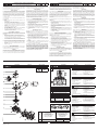
VALVE DISASSEMBLY
Disassemblein an orderlyfashion.Paycareful attention to
exploded views provided for identification of parts.
1. Removeretainingclipandsliptheentiresolenoidenclosure
offthesolenoidbasesub-assembly.CAUTION:whenmetal
retaining clip disengages, it can spring upwards.
2. Removethespringwasher.Unscrewscrews(4x)andremove
solenoidbasesub-assembly.Removecorespring,core
assembly and diaphragm spring.
3. Remove diaphragm/seat-assemblyand valvebody
O-ring.
4. Allpartsarenowaccessibleforcleaningorreplacement.
VALVE REASSEMBLY
Reassembleinreverseorder of disassemblypaying careful
attention to exploded views provided for identification and
placement of parts.
1. NOTE:Lubricateallgaskets/O-ringswithhighqualitysilicone
grease.ReplacevalvebodyO-ringanddiaphragm/seat-as-
sembly.
CAUTION:locatepilotholeindiaphragm/seat-assemblyat
45degreesfromthevalveoutlet.
2. Replacediaphragmspring,coreassembly,corespringand
thesolenoidbasesub-assembly,andtorquethescrews(4x)
in a criss-cross manner according to torque chart.
3. Replacespringwasher,solenoidenclosureandretainingclip.
4. Aftermaintenance,operatethevalveafewtimestobesure
of proper operation.
A separate Declaration of Incorporation relating to EEC-Di-
rective 89/392/EEC Annex II B is available on request. Please
provide acknowledgement number and serial numbers
of products concerned. This product complies with the
essential requirements of the EMC-Directive 89/336/EEC
and amendments as well as the 73/23/EEC + 93/68/EEC Low
Voltage Directives. A separate Declaration of Conformity is
available on request.
DESCRIPTION
Lesvannesdelasérie210fontpartiedelagammedesélec-
trovannes2-voies,normalementfermées,àcommandeassistée,
membranenonattelée.Cettevannepeutêtremontéeensérie
etauneentréehorizontalecommuneetunesortiehorizontale
unique.Lecorpsestenlaiton.
MONTAGE
LescomposantsASCO Numatics sontconçuspour les do-
mainesde fonctionnementindiquéssurlaplaquesignalétique
ouladocumentation.Aucunemodicationnepeutêtreréalisée
surle matérielsansl’accordpréalable dufabricant oude son
représentant.Avantdeprocéderaumontage,dépressuriserles
canalisations et effectuer un nettoyage interne.
Lesélectrovannes peuventêtre montédansn’importe quelle
position.
Lesens decirculationduuideestindiquéparrepères surle
corps et dans la documentation.
Ladimensiondestuyauteriesdoitcorrespondreauraccordement
indiquésurlecorps,l’étiquetteoulanotice.
Attention:
• Unerestrictiondestuyauteriespeutentraînerdesdysfonc-
tionnements.
• Andeprotégerlematériel,installerunecrépineouunltre
adéquatenamont,aussiprèsquepossibleduproduit.
• Encasd’utilisationderuban,pâte,aérosolouunlubriantlors
duserrage,veillezàcequ’aucuncorpsétrangernepénétre
dans le circuit.
• Utiliserunoutillageappropriéetplacerlesclésaussiprès
que possible du point de raccordement.
• And’évitertoutedétérioration,NEPASTROPSERRERles
raccords des tuyauteries.
• Nepasseservirdelavanneoudelatêtemagnétiquecomme
d’unlevier.
• Lestubesderaccordementnedevrontexerceraucuneffort,
couple ou contrainte sur le produit.
RACCORDEMENT ÉLECTRIQUE
Leraccordementélectrique doit êtreréalisépar unpersonnel
qualiéetselonlesnormesetrèglementslocaux.
Attention:
• Avanttouteintervention,couperl’alimentationélectriquepour
mettre hors tension les composants.
• Toutes lesbornesà visdoiventêtreserréescorrectement
avant la mise en service.
• Selonlatension,lescomposantsélectriquesdoiventêtremis
àlaterreconformémentauxnormesetrèglementslocaux.
Selonlescas,leraccordementélectriques’effectuepar:
• ConnecteursdébrochablesISO-4400(avecdegrédeprotec-
tionIP-65lorsqueleraccordementestcorrectementeffectué).
• Bornes àvis solidairesdu bobinage,sousboîtierétanche
avecpresse-étoupe«Pg».
• Filsoucâblessolidairesdelabobine.
MISE EN SERVICE
Avant de mettre le circuit sous pression, effectuer un essai
électrique.Danslecasd’uneélectrovanne,mettrelabobinesous
tensionplusieursfoisetécouterle“clic”métalliquequisignalele
fonctionnementdelatêtemagnétique.
FONCTIONNEMENT
Laplupartdesélectrovannescomportentdesbobinagesprévus
pourmisesoustensionpermanente.Pourévitertoutebrûlure,ne
pastoucherlatêtemagnétiquequi,enfonctionnementnormal
etenpermanencesoustension,peutatteindreunetempérature
élevée.Sil’électrovanneestfacilementaccessible,l’installateur
doitprévoiruneprotectionempêchanttoutcontactaccidentel.
BRUIT DE FONCTIONNEMENT
Lebruitdefonctionnement varieselonl’utilisation,leuide et
letypedematérielemployé.L’utilisateurnepourradéterminer
avecprécisionle niveausonoreémisqu’aprèsavoirmontéle
composantsurl’installation.
ENTRETIEN
L’entretiennécessaireauxproduitsASCONumaticsvarieavec
leursconditionsd’utilisation.Ilestsouhaitabledeprocéderàun
nettoyagepériodiquedontl’intervallevariesuivantlanaturedu
uide,lesconditionsdefonctionnementetlemilieuambiant.Lors
del’intervention,les composants doiventêtre examinéspour
détectertouteusureexcessive.Unensembledepiècesinternes
estproposéenpiècesderechangepourprocéderàlaréfection.
Encasdeproblèmelorsdumontage/entretienouencasdedoute,
veuillezcontacterASCONumaticsousesreprésentantsofciels.
DEMONTAGE DE LA VANNE
Démonterdefaçonméthodique.surlesvuesenéclatéfournies
danslapochetteetdestinéesàl’identicationdespièces.
1. Oterleclipdemaintienetfaireglisserl’ensembleduboîtier
dusolénoïdehorsdusous-ensembledelabasedusolénoïde.
ATTENTION:lorsqueleclipdemaintienmétalliqueestôté,
il peut bondir vers le haut.
2. Ôterlarondelle élastique. Dévisser lesvis(4x) etôterle
sous-ensembledebasedelatêtemagnétique.Ôterleressort
du noyau, le noyau et le ressort de la membrane.
3. Ôterlemontagedelamembrane/siègeetlejointtoriquedu
corps de la vanne.
4. Vouspouvezdèsàprésentnettoyerouremplacertoutesles
pièces.
REMONTAGE DE LA VANNE
Remonterensensinverse.
1. NOTE:Lubriertous lesjointsd’étanchéité/joints toriques
avecdelagraissesiliconedehautequalité.Replacerlejoint
torique du corps de la vanne et le montage de la membrane/
siège.ATTENTION:placerletroudepositionnementdansle
montagedelamembrane/siègeà45degrésdelasortiede
la vanne.
2. Replacerleressortdelamembrane,lenoyau,leressortdu
noyauetlesous-ensembledebasedelatêtemagnétique
etraccorderlesvis(4x)enlesentrecroisantselonleschéma
de couple.
3. Replacerlarondelleélastique,leboîtierdelatêtemagnétique
et le clip de maintien.
4. Aprèsl’entretien,fairefonctionnerlavannequelquesfoisan
des’assurerqu’elles’ouvreetsefermecorrectement.
Conformément à la directive CEE 89/392/CEE Annexe II B,
une Déclaration d’incorporation peut être fournie sur de-
mande. Veuillez nous indiquer le numéro d’accusé de récep-
tion (AR) et les références ou codes des produits concernés.
Ce produit est conforme aux exigences essentielles de la
Directive 89/336/CEE sur la Compatibilité Electromagnétique,
et amendements et les directives Basse Tension 73/23/CEE +
93/68/CEE. Une déclaration de conformité peut être fournie
sur simple demande.
BESCHREIBUNG
Bei der Baureihe 210 handelt es sich um normal geschlossene,
vorgesteuerte 2-Wege-Magnetventile mit vorgesteuerter Mem-
bran.DiesesVentilistfürKopplungsmontagegeeignetundbesitzt
einengemeinsamenhorizontalen Einlaßundeinen einzigen
horizontalenAuslaß.DasVentilgehäusebestehtausMessing.
EINBAU
DieASCONumatics-Komponentendürfennurinnerhalbderauf
denTypenschildern angegebenenDateneingesetzt werden.
VeränderungenandenProduktensindnurnachRücksprache
mitASCONumatics zulässig.Vordem EinbauderVentile
mußdasRohrleitungssystem drucklosgeschaltetund innen
gereinigt werden.
DieEinbaulagederProdukteistgenerellbeliebig.
DieDurchußrichtungundderRohrleitungsanschlußvonVentilen
sind gekennzeichnet.
DieRohrleitungsanschlüssesolltenentsprechenddenGrößen-
angabenaufdenTypenschildernmithandelsüblichenVerschrau-
bungendurchgeführtwerden.
Vorsicht:
• EineReduzierungderAnschlüssekannzuLeistungs-und
Funktionsminderungenführen.
• ZumSchutzderVentilesolltenfürdieBetriebsbedingungen
geeigneteSchmutzfängeroderFiltersodichtwiemöglichin
denVentileingangintegriertwerden.
• BeiAbdichtungamGewindeistdaraufzuachten,daßkein
DichtungsmaterialindieRohrleitungoderdasVentilgelangt.
• ZumEinbaudarfnurgeeignetesWerkzeugverwendetwer-
den,dassonahewiemöglichamAnschlußpunktanzusetzen
ist.
• Um eineBeschädigungder Produktezu vermeiden,istdar-
aufzuachten, daß dieRohranschlüsseNICHT ZUSTARK
ANGEZOGENwerden.
• SpuleundFührungsrohrvonVentilendürfennichtalsGe-
genhalter benutzt werden.
• DieRohrleitungsanschlüssesolltenuchtenunddürfenkeine
SpannungenaufdasVentilübertragen.
ELEKTRISCHER ANSCHLUSS
DerelektrischeAnschlußistvonFachpersonalentsprechendden
geltendenVDE-undCEE-Bestimmungenauszuführen.
Vorsicht:
• VorBeginnderArbeitenistsicherzustellen,daßalleelektrischen
LeitungenundNetzteilespannungslosgeschaltetsind.
• AlleAnschlußklemmensindnachBeendigungderArbeiten
vorschriftsmäßigentsprechendden geltenden Normen
anzuziehen.
• JenachSpannungsbereichmußdasVentilnachdengelten-
denBestimmungenundNormeneinenSchutzleiter-anschluß
erhalten.
DerMagnetantriebkannje nachBauart folgendeelektrische
Anschlüsseaufweisen:
• FlachsteckeranschlüssegemäßISO-4400(beiordnungsge-
mäßerMontageistSchutzartlP-65gewährleistet).
• IntegrierteSchraubanschlüsseinwasserdichterKapselung
mitPg-Kabelverschraubung.
• EingegosseneKabelenden.
INBETRIEBNAHME
VorDruckbeaufaufschlagungdesProduktessollteeineelektri-
scheFunktionsprüfungerfolgen:BeiMagnetventilenSpannung
anderMagnetspulemehrmalsein-undausschalten.Esmußein
metallischesKlickenzuhörensein.
BETRIEB
DiemeistenMagnetventile sindmitSpulen fürDauerbetrieb
ausgerüstet.ZurVermeidungvonPersonen-undSachschäden
solltejedeBerührungderMagnetspulevermiedenwerden,da
dieseunternormalenBetriebsbedingungensehrheiß werden
kann.BeileichtzugänglichemMagnetventilsolltevomInstallateur
einSchutzvorgesehen werden,um jeglichesversehentliches
Berührenzuvermeiden.
GERÄUSCHEMISSION
DieGeräuschemissionhängt sehrstarkvom Anwendungsfall,
dem Medium, mit denen das Produkt beaufschlagt wird, und
derArtdesverwendetenProduktesab.DieexakteBestimmung
desGeräuschpegelskann aus diesemGrundnur durch die
Persondurchgeführtwerden,die dasVentil in dasjeweilige
System eingebaut hat.
WARTUNG
DieWartung hängtvon denBetriebsbedingungenab. Eswird
empfohlen,dasProduktregelmäßigzureinigen,wobeisichdie
ZeitabständenachdemMediumunddenBetriebsbedingungen
richten.WährendderWartungsolltendie Komponentenauf
übermäßigenVerschleißüberprüftwerden.FürdieÜberholung
derASCONumatics-ProduktesindkompletteSätzemitinternen
Teilen alsErsatzteilsätzeerhältlich.TretenSchwierigkeitenbei
Einbau,BetrieboderWartungaufsowiebeiUnklarheiten,istmit
ASCONumaticsRücksprachezuhalten.
VENTILDEMONTAGE
DasVentilmußinderangegebenenReihenfolgezerlegtwerden.
DabeisinddieTeileexaktanhanddermitgeliefertenExplosions-
zeichnungen zu identifizieren.
1. Klammerhalterung entfernen undMagnetspulengehäuse
komplettausderHaltemutterherausziehen.
ACHTUNG:DieKlammerhalterungkannbeimLösennach
oben wegfedern.
2. Federscheibeentfernen.Schrauben (4x) lösenund Halte-
mutter entfernen. Ankerfeder, Magnetankerbaugruppe und
Membranfeder entfernen.
3. Membran-/VentilsitzbaugruppeundVentilgehäuse-Dichtungs-
ring entfernen.
4. NunsindalleTeile,diegereinigtoderausgetauschtwerden
müssen,leichtzugänglich.
VENTILZUSAMMENBAU
VentilinderumgekehrtenReihenfolgewiebeiderDemontage
zusammenbauen.DabeisinddieTeileanhandderExplosions-
zeichnungen zu identifizieren und anzuordnen.
1. HINWEIS:AlleDichtungen/Dichtungsringesindmithochwer-
tigemSilikonfettzuschmieren.Ventilgehäuse-Dichtungsring
undMembran-/Ventilsitzbaugruppewiedermontieren.
ACHTUNG: Führungsbohrung inderMembran-/Ventilsitz-
baugruppe45GradvomVentilausgangversetztanordnen.
2. Membranfeder, Magnetankerbaugruppe, Ankerfeder und
Haltemutterwiedermontieren undSchrauben(4x) kreuz-
weiseentsprechenddenAngabenimDrehmomentdiagramm
anziehen.
3. Federscheibe,MagnetkopfgehäuseundHalteklammerwieder
montieren.
4. NachderWartungVentil mehrmals betätigen, umsicher-
zustellen,daßesordnungsgemäßfunktioniert.
Eine separate Herstellererklärung im Sinne der Richtlinie
89/392/EWG Anhang II B ist auf Anfrage erhältlich. Geben Sie
bitte für die betreffenden Produkte die Nummer der Auftrags-
bestätigung und die Seriennummer an. Das Produkt erfüllt die
wesentlichen Anforderungen der EMV-Richtlinie 89/336/EWG
und Ergänzungen sowie der Niederspannungsrichtlinien
73/23/EWG und 93/68/EWG. Eine separate Konformitätser-
klärung ist auf Anfrage erhältlich.
DESCRIPCION
LaSerie210estáformadaporválvulasde2vías,normalmente
cerradas,activadasporpiloto,dediafragmaotante.Estaválvula
puedemontarseentándemytieneunaentradahorizontalco-
múnyunasalidahorizontalúnica.Elcuerpodelaválvulaestá
construido de latón.
INSTALACION
LoscomponentesASCONumaticssólodebenutilizarsedentro
delasespecicacionestécnicasqueseespecicanensuplaca
decaracterísticas.Loscambiosenelequiposóloestaránper-
mitidosdespuésdeconsultaralfabricanteoasurepresentante.
Antesde lainstalación,despresuriceelsistemadetuberías y
limpie internamente.
Elequipopuedeutilizarseencualquierposición.
Enelcuerposeindicanelsentidodeluidoylaconexióndelas
válvulasalatubería.
Lasconexionesalatuberíadebencorresponderaltamañoindi-
cadoenlaplacadecaracterísticasyajustarseadecuadamente.
Precaución:
• Lareduccióndelasconexionespuedecausaroperaciones
incorrectas o defectos de funcionamiento.
• Paralaproteccióndelequiposedebeinstalarenlapartede
la entrada y tan cerca como sea posible del producto un filtro
o tamizador adecuado para el servicio.
• Sise utilizaracinta,pasta,sprayuotroslubricantesenel
ajuste,sedebeevitarqueentrenpartículasenelproducto.
• Sedebeutilizarlasherramientasadecuadasycolocarllaves
lomáscercaposibledelpuntodeconexión.
• Paraevitardañosalequipo,NOFORZARlasconexionesa
latubería.
• Noutilizarlaválvulaoelsolenoidecomopalanca.
• Lasconexionesalatuberíanoproduciránningunafuerza,
apriete o tensión sobre el producto.
CONEXION ELECTRICA
Encasoderequerirseconexioneseléctricas,estasseránrealiza-
dasporpersonalcualicadoydeberánadaptarsealasnormas
y regulaciones locales.
Precaución:
• Antesdecomenzareltrabajo,desconecteelsuministrode
energíaeléctricaydesenergiceelcircuitoelectrónicoylos
elementos portadores de tensión.
• Todoslosterminaleseléctricosdebenestarapretadosade-
cuadamente según normas antes de su puesta en servicio.
• Según el voltaje, loscomponenteselectrónicos deben
disponer de una conexión a tierra y satisfacer las normas y
regulaciones locales.
Elequipopuedetenerunodelossiguientesterminaleseléctricos:
• Conexiones desenchufables segúnlanormaISO-4400
(cuando se instala correctamente esta conexión proporciona
unaprotecciónIP-65).
• Terminalesdetornillosembutidosencajaherméticaalagua
conprensaestopasdecable«Pg».
• Salidadecables.
PUESTA EN MARCHA
Sedebeefectuarunapruebaeléctricaantesdesometerapre-
siónelsistema.Enelcasodelasválvulassolenoides,sedebe
energizar varias veces la bobina y comprobar que se produce
unsonidometálicoqueindicaelfuncionamientodelsolenoide.
SERVICIO
Lamayorpartedelasválvulassolenoidessesuministrancon
bobinas para un servicio continuo. Con el fin de evitar la posibilidad
dedañospersonalesomaterialesnosedebetocarelsolenoide,
ya que puede haberse calentado en condiciones normales de
trabajo.Silaelectroválvulaesdefácilacceso,elinstaladordebe
prever una protección que impida cualquier contacto accidental.
EMISION DE RUIDOS
Laemisiónderuidosdependedelaaplicación,medioynatu-
ralezadelequipoutilizado.Unadeterminaciónexactadelnivel
de ruido solamente se puede llevar a cabo por el usuario que
dispongalaválvulainstaladaensusistema.
MANTENIMIENTO
ElmantenimientodelosproductosASCONumaticsdependede
las condiciones de servicio. Se recomienda una limpieza perió-
dica, dependiendo de las condiciones del medio y del servicio.
Duranteelservicio,loscomponentesdebenserexaminadospor
sihubieradesgastesexcesivos.Sedisponedeunjuegocompleto
de partes internas como recambio. Si ocurriera un problema
durante la instalación/mantenimiento o en caso de duda contactar
con ASCO Numatics o representantes autorizados.
DESMONTAJE DE LA VALVULA
Desmontelaválvulaordenadamente.Presteespecialatencióna
las vistas ampliadas que se suministran para identificar las partes.
1. Retireelclipdesujeciónydeslicelacubiertaconelsolenoide
delconjuntodelabasedelsolenoide.
PRECAUCION:al desengancharse elclip de sujeción
metálico,éstepuedesaltarhaciaarriba.
2. Retirela arandelaresorte.Retirelos4tornillosyretirela
baseauxiliardelsolenoide.Retireelresortedelnúcleo,el
conjuntodelnúcleoyelresortedeldiafragma.
3. Retireelconjuntodeldiafragma/asientoylajuntadelcuerpo
delaválvula.
4. Ahoratendráaccesoatodaslaspiezasparasulimpiezao
sustitución.
REMONTAJE DE LA VALVULA
Vuelvaamontarlaválvulaenelordeninversodedesmontaje
prestando especial atención a las vistas ampliadas suministradas
para identificar e instalar las partes.
1. NOTA:Lubriquetodaslasguarniciones/juntascongrasade
siliconadebuenacalidad.Vuelvaacolocarlajuntadelcuerpo
delaválvulayelconjuntodeldiafragma/asiento.
PRECAUCION:localiceeloriciodelpilotoenelconjunto
deldiafragma/asientoa45gradosdelasalidadelaválvula.
2. Vuelvaacolocarelresortedeldiafragma,conjuntodelnúcleo,
resorte del núcleo y la base auxiliar del solenoide y apriete
los4tornillosdeformacruzada,segúnelcuadrodeapriete.
3. Vuelvaacolocarlaarandelaresorte,lacajadelsolenoidey
elclipdesujeción.
4. Despuésderealizado el mantenimiento, opere laválvula
unas cuantas veces para asegurarse de su correcto funcio-
namiento.
Se dispone, por separado y bajo demanda, de una Declara-
ción de Incorporación conforme a la Directiva CEE 89/392/
EEC Anexo II B. Rogamos que nos faciliten los números de
serie y de aceptación de pedido de los productos correspon-
dientes. Este producto cumple con los requisitos esenciales
de la Directiva CEM 89/336/CEE y sus correspondientes
modificaciones y las directivas Baja Tensión 73/23/CEE +
93/68/CEE. Si lo desea, podemos facilitarle una Declaración
de Conformidad bajo demanda.
IM396-1/pg.1
123620-593
INSTALLATION AND MAINTENANCE INSTRUCTIONS
normally closed, pilot operated, floating diaphragm, high flow and
gangmounting,3/4
INSTRUCTIONS D’INSTALLATION ET D’ENTRETIEN
normalementfermée,àcommandeassistée,àmembranenon
attelée,àgranddébitetmontageensérie,3/4
BETRIEBSANLEITUNG
Magnetventile, normal geschlossen, vorgesteuerte Membrane,
fürhohenDurchußundKopplungsmontage,3/4
INSTRUCCIONES DE INSTALACIÓN Y MANTENIMIENTO
normalmente abierta, accionada por piloto, de diafragma flotante,
ujoelevadoymontajeentándem,3/4
La page est en cours de chargement...
-
 1
1
-
 2
2


Asco Series 210 3/4 AC Floating/Hung Diaphragm Le manuel du propriétaire
- Taper
- Le manuel du propriétaire
dans d''autres langues
- italiano: Asco Series 210 3/4 AC Floating/Hung Diaphragm Manuale del proprietario
- English: Asco Series 210 3/4 AC Floating/Hung Diaphragm Owner's manual
- español: Asco Series 210 3/4 AC Floating/Hung Diaphragm El manual del propietario
- Deutsch: Asco Series 210 3/4 AC Floating/Hung Diaphragm Bedienungsanleitung
- Nederlands: Asco Series 210 3/4 AC Floating/Hung Diaphragm de handleiding