Lifetime 90176 Le manuel du propriétaire
- Taper
- Le manuel du propriétaire

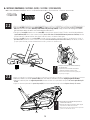
• Decide with what to fi ll the the base
(sand is recommended)
• At least 2 people recommended for setup
Pour le français, voir la page 2. Para el español, ver la página 3.
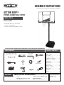
ASSEMBLY INSTRUCTIONS
ACTION GRIP®
PORTABLE BASKETBALL SYSTEM
MODEL 90176
BEFORE ASSEMBLY:
CONTACT LIFETIME® CUSTOMER SERVICE:
Dial 1-800-225-3865
QUESTIONS? MODEL# AND PRODUCT ID
(both are needed when contacting us)
Model Number: 90176
Product ID:
For Customer Service in Mainland Europe
and the United Kingdom,
E-mail: [email protected]
Live Chat:
www.lifetime.com/customerservice/home
(click on “LIVE CHAT” tab)
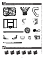
Icon Legend...................................................4
Warnings & Notices......................................5
Pole Assembly...............................................6
Pole-to-Base Assembly..............................11
Backboard-to-Rim Assembly.....................15
Backboard-to-Pole Assembly.....................19
Parts Identifi er..........................................i–iv
Handle Assembly........................................24
Final Assembly............................................31
Moving the System.....................................35
Maintenance Instructions..........................36
Warning Sticker...........................................37
Registration..............................................38
Warranty....................................................41
(x2)
(x1)
(x1)
(x1)
(x1)
(x1)
(x1)
(x1)
1/2" (≈13 mm), 7/16" (≈11 mm),
9/16" (≈14 mm), 3/4" (≈19 mm)
3/16" (≈5 mm)
(included)
375 lb (≈170 kg)
1/2" (≈13 mm)
(x2)
(x1)
(x1)
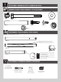
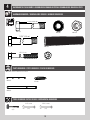
TOOLS REQUIRED TABLE OF CONTENTS
Save this instruction in the event that the manufacturer has to be contacted for replacement parts.

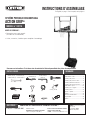
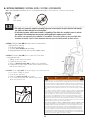
AVANT L’ASSEMBLAGE :
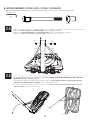
• Déterminer avec quoi remplir
(le sable est recommandé)
• Il faut, au moins, 2 adultes pour compléter l'assemblage
For English, see page 1. Para el español, ver la página 3.
INSTRUCTIONS D’ASSEMBLAGE
SYSTÈME PORTABLE DE BASKET-BALL
ACTION GRIP®
MODÈLE n° 90176
CONTACTER LES SERVICES À LA CLIENTÈLE LIFETIME® :
QUESTIONS ? N° DE MODÈLE ET RÉFÉRENCE DU
PRODUIT (il faut avoir les deux en entrant en
contact avec nous)
N° de modèle : 90176
Référence du produit :
OUTILS REQUIS SOMMAIRE
Pour nos services à la clientèle du continent
européen et au Royaume-Uni,
courriel : [email protected]
Légende des icônes........................................4
Avertissements et avis...................................5
Assemblage du poteau...................................6
Assemblage du poteau à la base...............11
Assemblage du tableau à l’anneau..............15
Assemblage du tableau au poteau.............19
Identifi cateur de pièces..............................i–iv
Assemblage de la poignée..........................24
Assemblage fi nal..........................................31
Déplacer le systèm.......................................35
Entretien.......................................................36
Autocollant d’avertissement.........................37
Enregistrement............................................38
Garantie.......................................................42
(x2)
(x1)
(x1)
(x1)
(x1)
(x1)
(x1)
(x1)
≈13 mm (1/2 po), ≈11 mm (7/16 po),
≈14 mm (9/16 po), ≈19 mm (3/4 po)
≈5 mm (3/16 po)
(incluses)
≈170 kg (375 lb)
≈13 mm (1/2 po)
(x2)
(x1)
(x1)
SA-
BLE
Composer le 1-800-225-3865 Entretien en direct :
www.lifetime.com/customerservice/home
(cliquer sur la languette « LIVE CHAT »)
Conserver ces instructions s'il est nécessaire de contacter le fabricant pour obtenir des pièces de remplacement.

For English, see page 1. Pour le français, voir la page 2.
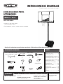
INSTRUCCIONES DE ENSAMBLAJE
MODELO n° 90176
SISTEMA DE BALONCESTO PORTÁTIL
ACTION GRIP®
ANTES DE ENSAMBLAR:
• Decidir con que llenar la base
(se recomienda la arena)
• Recomendamos, al menos, 2 adultos para el ensamblaje
PONERSE EN CONTACTO CON LOS SERVICIOS DE CLIENTES LIFETIME®:
Marcar al 1-800-225-3865 Chat en vivo:
www.lifetime.com/customerservice/home
(cliquear en la lengüeta «LIVE CHAT»)
¿PREGUNTAS? MODEL E ID DEL PRODUCTO
(se necesitan los dos al contactarnos)
Número de modelo: 90176
ID del producto:
INSTRUMENTAL REQUERIDO ÍNDICE
Para nuestros servicios a clientes en el
continente europeo y el Reino Unido,
correo eléctronico:
Leyenda de íconos......................4
Advertencias y avis.....................5
Ensamblaje del poste..................6
Ensamblaje del poste a la base...11
Ensamblaje del tablero al aro.....15
Ensamblaje del tablero al poste..19
Identifi cador de piezas.............i–iv
Ensamblaje de la manivela........24
Ensamblaje fi nal.......................31
Deplazando el sistema...............35
Mantenimiento.......................36
Autoadhesivo de advertencia......37
Registro...............................38
Garantía................................43
(x2)
(x1)
(x1)
(x1)
(x1)
(x1)
(x1)
(x1)
1/2 in. (≈13 mm), 7/16 in. (≈11 mm),
9/16 in. (≈14 mm), 3/4 in. (≈19 mm)
3/16 in. (≈5 mm)
(incluidas)
≈170 kg (375 lb)
1/2 in. (≈13 mm)
(x2)
(x1)
(x1)
ARENA
Guardar estas instrucciones en caso de tener que contactar el fabricante para obtener piezas de reemplazo.

4
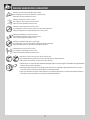
• Indicates the parts to be used for a section.
• Ceci indique les pièces requises pour une section.
• Indica las piezas requeridas para una sección.
• Indicates special heed should be taken when reading.
• Ceci indique que vous devez faire attention à ce que vous lisez.
• Indica que uno debe prestar atención al leer.
• Indicates the hardware to be used for a section.
• Ceci indique la quincaillerie requise pour une section.
• Indica el herraje requerido para una sección.
• Indicates the tools to be used for a section.
• Ceci indique les outils requis pour une section.
• Indica el instrumental requerido para una sección.
• Indicates no hardware required for a specifi c page.
• Ceci indique qu’il n’y a pas de quincaillerie requise pour une page particulière.
• Indica que ningún herraje es requerido para una página específi ca.
• Indicates no parts required for a specifi c section.
• Ceci indique qu’il n’y a pas de pièces requises pour une section particulière.
• Indica que ninguna pieza es requerida para una sección específi ca.
• Indicates to use/not to use an electric drill for a specifi c step.
• Ceci indique utiliser/ne pas utiliser de perceuse électrique pour une étape particulière.
• Indica usar/no usar un taladro eléctrico para un paso específi co.
ICON LEGEND / LÉGENDE DES ICÔNES / LEYENDA DE ÍCONOS
• Indicates the use of a centerlock nut. A nut with this marking will require some e ort to tighten. This hardware was designed with this
feature in order to prevent loosening later.
• Cette image indique l’usage d’un écrou de blocage central. Un écrou avec ce marquage requerra plus d’e ort pour le serrer. Cet
écrou a été conçu avec cette fonction afi n d’empêcher son desserrage plus tard.
• Indica el uso de una tuerca de bloque central. Una tuerca con esta marca requerirá un poco de esfuerzo para apretarlo. Esta tuerca
fue diseñado con esta característica con el fi n de evitar su afl ojamiento más tarde.

5
WARNINGS & NOTICES / AVERTISSEMENTS ET AVIS / ADVERTENCIAS Y AVISOS
Most injuries are caused by misuse and/or not following instructions. Use caution when using this product.
To ensure safety, do not attempt to assemble this product without following the instructions carefully. Check entire box and inside all packing
material for parts and/or additional instruction material. Before beginning assembly, read the instructions and identify parts using the hardware
identifi er and parts list in this document. Proper and complete assembly, use and supervision are essential for proper operation and to reduce the
risk of accident or injury. A high probability of serious injury exists if this product is not installed, maintained, and operated properly.
FAILURE TO FOLLOW THESE WARNINGS MAY RESULT IN SERIOUS INJURY OR PROPERTY DAMAGE AND WILL VOID WARRANTY.
Owner must ensure that all players know and follow these rules for safe operation of the system.
• If using a ladder during assembly, use extreme caution.
• Two capable adults are recommended for this operation.
• Check base daily for leakage. Leaks will cause system to fall.
• Assemble the pole sections properly. Failure to do so could cause the pole sections to separate during play or transport.
• Minimum operational height is 6 ft 6 in (1.98 m) to the bottom of the backboard.
SAFETY INSTRUCTIONS
La mayoría de las lesiones son causadas por el abuso y/o por el no seguir las instrucciones. Sea cauteloso al usar este producto.
Para su seguridad, no intente ensamblar este producto sin leer y seguir todas las instrucciones cuidadosamente. Revise la caja entera y todos los
materiales de embalaje en busca de piezas y / o material de instrucciones adicional. Antes de comenzar el ensamble, identifi que todas las piezas y el
equipo usando las listas de partes y equipo así como los identifi cadores en este documento. El ensamble correcto y completo, el uso y la supervisión
son esenciales para una orientación apropiada y para reducir el riesgo de un accidente o lesión. Existe una alta probabilidad de sufrir lesiones graves
si este producto no es instalado, mantenido y / o operado correctamente.
EL INCUMPLIMIENTO DE SEGUIR ESTAS ADVERTENCIAS PUEDE OCASIONAR EN LESIONES GRAVES Y/O DAÑO A LA PROPIEDAD Y ANULARÁ LA GARANTÍA.
El propietario debe asegurarse de que todos los jugadores conocen y seguir estas reglas para la operación segura del sistema.
• Si utiliza una escalera durante el ensamble, tenga mucho cuidado.
• Se recomienda la participación de dos adultos capaces para esta ensamble.
• Compruebe si hay fugas en la base. Las fugas pueden causar que el producto caiga.
• Ensamble las secciones del poste correctamente. De lo contrario, podría provocar que las secciones del poste se separaran
durante el juego o el transporte.
• Altura mínima de operación es 1,98 m (6 ft 6 in) a la parte inferior del tablero.
INSTRUCCIONES DE SEGURIDAD
La majorité des accidents résultent d’une mauvaise utilisation et/ou du fait de n’avoir pas suivi les consignes. Observez toutes précautions utiles pendant
l’utilisation de ce produit.
Pour assurer votre sécurité, ne tentez pas d’assembler cet article sans avoir lu et suivi toutes les consignes attentivement. Vérifi ez la totalité de la
boîte et l’intérieur de tous les matériaux d’emballage pour trouver toutes les pièces et/ou matériau contenant des consignes supplémentaires. Avant
de commencer le montage, identifi ez toutes les pièces et tous les accessoires et faites-en l’inventaire en les comparant aux listes et identifi cateurs
de pièces et accessoires contenus dans ce document. Un montage correct et complet ainsi que l’utilisation et la supervision correctes sont des
conditions essentielles à la bonne direction et diminuent les risques d’accident ou de blessure. Une haute probabilité d’accident grave résulte de
mauvaises conditions d’installation, maintenance et/ou utilisation.
LE NON-RESPECT DE CES AVERTISSEMENTS PEUT DONNER LIEU À DES ACCIDENTS GRAVE OU DES DOMMAGES MATÉRIELS ET ANNULER LA GARANTIE.
Le propriétaire doit veiller à ce que tous les joueurs connaissent et suivent ces règles pour une exploitation sûre du système.
• Agissez avec la plus grande prudence si vous employez une échelle pour l’assemblage.
• Il est recommandé que ce montage soit exécuté par deux personnes adultes.
• Vérifi ez quotidiennement la base au niveau de fuites. Les fuites peuvent causer la chute du système.
• Montez les sections de poteau correctement. La non-observation de cette consigne peut amener les sections de poteau à se séparer
pendant le jeu ou le déplacement.
• La hauteur minimale est de 1,98 m (6 pi 6 po) au bas de la planche.
CONSIGNES DE SÉCURITÉ

6
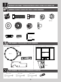
BCO
Metal Parts / Piezas de metal / Pièces en métal
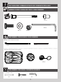
TOOLS REQUIRED / INSTRUMENTAL REQUERIDO / OUTILS REQUIS
PARTS REQUIRED / PIEZAS REQUERIDAS / PIÈCES REQUISES
HARDWARE REQUIRED / HERRAJE REQUERIDO / ACCESSOIRES REQUIS
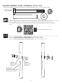
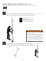
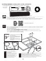
POLE ASSEMBLY / ENSAMBLE DEL POSTE / ASSEMBLAGE DU POTEAU
1
Phillips Screwdriver
Destornillador de estrella
Tournevis cruciforme
Scrap Wood
Plaquita de madera
Chute de bois
ALL (x1)
Electric Drill
Taladro eléctrico
Perceuse électrique
Warning Sticker / Etiqueta adhesiva de
advertencia / Autocollant d’avertissement
ADS (x2)
ABZ (x2)
ABB (x2)
AAF (x2)
ABE (x2)
ABR (x2)
CIH (x2)
ALH (x1)
ALF (x1)
9/16" (14 mm)
(2)
ALE (x1) !• The bottom pole (ALE) has been designed with
an indent at one end.
• Le poteau inférieur (ALE) a été conçu avec une
marque sur une extrémité
• El poste inferior (ALE) ha sido diseñado con una
marca en un extremo.

7
TOOLS AND HARDWARE REQUIRED / INSTRUMENTAL Y HERRAJE REQUERIDOS / OUTILS ET ACCESSOIRES REQUIS
• If you have trouble with this section, scan the code below to view a video on how to assemble the Pole.
• Si tiene problemas con esta sección, siga el código debajo para ver un video sobre el ensamble del Poste.
• Si vous avez des problèmes avec cette section, suivez le code en bas pour voir un vidéo sur l’assemblage du
Poteau.
SECTION 1 (CONTINUED) / SECCIÓN 1 (CONTINUACIÓN) / SECTION 1 (SUITE)
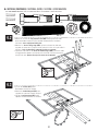
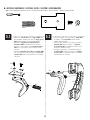
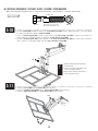
• Secure the Pole Bracket (ALL) to the Middle Pole (ALF) with the hardware as shown.
• Sujete el Soporte de poste (ALL) al Poste intermedio (ALF) usando el herraje ilustrado.
• Attachez le Support de poteau (ALL) au Poteau du milieu (ALF) à l’aide des accessoires illustrés.
1.1
• http://go.lifetime.com/actiongrippoleassembly
!
ALF
ABE
ABR
Warning Sticker
Etiqueta adhesiva de advertencia
Autocollant d’avertissement
AAF
Large Holes
Agujeros grandes
Grands trous
Small Holes
Agujeros pequeños
Petits trous
AAF (x2)
ABE (x2)
ABR (x2)
9/16" (14 mm) (x2)
ABB (x2)
ABB
ALL

8
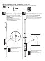
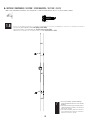
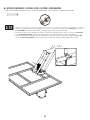
• Align the hole in the bottom of the Top Pole (ALH)
with the slot in the top of the Middle Pole (ALF).
• Alinee el agujero en la parte inferior del Poste
superior (ALH) con la ranura en la parte superior del
Poste intermedio (ALF).
• Alignez le trou dans la partie inférieure du
Poteau supérieur (ALH) avec la fente dans la partie
supérieure du Poteau du milieu (ALF).
• Secure the Middle Pole to the Bottom Pole (ALE) using
the same method as step 1.2.
• Sujete el Poste intermedio al Poste inferior (ALE)
usando el mismo método del paso 1.2.
• Attachez bien le Poteau du milieu au Poteau inférieur
(ALE) en utilisant le même méthode de l’étape 1.2.
1.2 1.3
!• The Screw should be fl ush with the Pole, but
will spin freely once inserted.
• El Tornillo debe estar a ras del Poste, mas
girará libremente una vez insertado.
• La Vis doit ser au ras du Poteau, mais elle
tournera librement une fois insérée. !• The Screw should be fl ush with the Pole, but
will spin freely once inserted.
• El Tornillo debe estar a ras del Poste, mas
girará libremente una vez insertado.
• La Vis doit ser au ras du Poteau, mais elle
tournera librement une fois insérée.
TOOLS AND HARDWARE REQUIRED / INSTRUMENTAL Y HERRAJE REQUERIDOS / OUTILS ET ACCESSOIRES REQUIS
1.2
SECTION 1 (CONTINUED) / SECCIÓN 1 (CONTINUACIÓN) / SECTION 1 (SUITE)
ADS (x2)
1.3 CIH (x2)
ALH
ALF
ADS
ALH
ALF
CIH
ALF
ALE
ADS
ALF
ALE
CIH

9
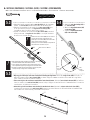
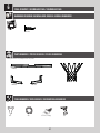
• Strike the end of the Pole Assembly on a piece of scrap wood or cardboard 5–6 times.
• Golpee el extremo del Ensamble del poste en una plaquita de madera o cartón 5–6 veces.
• Frappez l’extrémité de l’Assemblage du poteau sur une chute de bois ou carton 5 – 6 fois.
1.4
6x
WARNING / AVERTISSEMENT / ADVERTENCIA
!
!
The poles must be seated together! The poles must be struck on a
hard surface fi ve to six times! Failure to seat the poles correctly could
allow the poles to separate during use.
¡Deben asentarse las secciones del poste! ¡Es imperativo golpear
las secciones cinco a seis veces! El incumplimiento de asentar las
secciones correctamente puede ocasionar la separación de las
secciones durante el juego.
Les poteaux doivent s’enclencher les uns dans les autres ! Même si
le poteau recouvre la fente avant de s’enclencher, il faut les frapper
sur un morceau de bois cinq à six fois! Un mauvais enclenchement
des poteaux peut entraîner leur séparation lors de l’utilisation.
• Do not strike your feet with the Pole sections, as
serious injury may occur.
• No golpee los pies con las Secciones del poste, ya
que esto puede ocasionarle graves lesiones.
• Ne pas se cogner les pieds avec les Sections du
poteau ; ceci peut causer des blessures graves.
!
• Flip the Pole over and repeat step 1.4 for the opposite end of the Pole Assembly.
• Dé la vuelta el Poste, y repita el paso 1.4 para el extremo opuesto del Ensamble del poste.
• Renversez le Poteau, et répétez l’étape 1.4 pour l’extrémité opposée de l’Assemblage du poteau.
1.5
6x
TOOLS AND HARDWARE REQUIRED / INSTRUMENTAL Y HERRAJE REQUERIDOS / OUTILS ET ACCESSOIRES REQUIS
SECTION 1 (CONTINUED) / SECCIÓN 1 (CONTINUACIÓN) / SECTION 1 (SUITE)

10
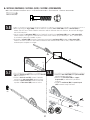
• Secure the poles together with Self-drilling Screws (ABZ).
• Sujete los Postes el uno al otro con Tornillos autoroscantes (ABZ).
• Attachez les Poteaux l’un à l’autre à l’aide des Vis autotaraudeuses (ABZ).
1.6
ABZ (x2)
• For ease of installation, chuck the Self-Drilling
Screws directly into the drill, or use a 3/8” (10 mm)
Hex Driver.
• Para facilitar la instalación, fi je los Tornillos autoros-
cantes directamente en el taladro, o use una llave de
tuerca de 3/8” (10 mm).
• Pour faciliter l’installation, mettez les Vis autotarau-
deuses directlement dans la Perceuse, ou utilisez un
tournevis à écrou de 3/8” (10 mm).
!
TOOLS AND HARDWARE REQUIRED / INSTRUMENTAL Y HERRAJE REQUERIDOS / OUTILS ET ACCESSOIRES REQUIS
SECTION 1 (CONTINUED) / SECCIÓN 1 (CONTINUACIÓN) / SECTION 1 (SUITE)
ALH
ALF
ALE
ABZ
ABZ

11
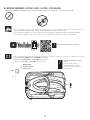
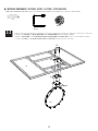
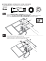
POLE-TO-BASE ASSEMBLY / ASSEMBLAGE DU POTEAU À LA BASE / ENSAMBLAJE DEL POSTE A LA BASE
2
BCQ
Metal Parts / Pièces en métal / Piezas de metal
TOOLS REQUIRED / OUTILS REQUIS / INSTRUMENTAL REQUERIDO
PARTS REQUIRED / PIÈCES REQUISES / PIEZAS REQUERIDAS
HARDWARE REQUIRED / QUINCAILLERIE REQUISE / HERRAJE REQUERIDO
AAE (x2)
BTS (x1)
ABD (x4) AAO (x2)
EEO (x2)
AMU (x2)
AJM (x1)
Plastic Parts / Pièces en plastique / Piezas de plástico
(x2) (x1)
3/16 in/po (≈5 mm)
(x2)
AJD (x1)
ALI (x2)
AJN (x1)
DRZ (x1)
1/2 in/po (≈13 mm)

12
TOOLS AND HARDWARE REQUIRED / OUTILS ET QUINCAILLERIE REQUIS / INSTRUMENTAL Y HERRAJE REQUERIDOS
SECTION 2 (CONTINUED) / SECTION 2 (SUITE) / SECCIÓN 2 (CONTINUACIÓN)
• If you have trouble with this section, scan the code below to view a video on on its assembly.
• En cas d’avoir des problèmes avec cette section, scannez le QR code en dessous pour voir un vidéo de l’assemblage.
• En caso de tener problemas con esta sección, escanee el código QR debajo para ver un video del ensamblaje.
• Make sure the rubber gasket is inside the
base cap.
• Assurez-vous que le joint en
caoutchouc est dans le capuchon.
• Asegúrese que la tapa de goma está
dentro del tapón.
• http://go.lifetime.com/powerliftassembly-section2
!
AJM
AJN
AJN
Rubber gasket
Joint en caoutchouc
Junta de goma
!
2.1 • Screw the base cap (AJN) onto the base (AJM) as indicated.
• Attachez le capuchon (AJN) à la base (AJM) comme indiqué.
• Atornille el tapón (AJN) a la base (AJM) como se inidica.

13
TOOLS AND HARDWARE REQUIRED / OUTILS ET QUINCAILLERIE REQUIS / INSTRUMENTAL Y HERRAJE REQUERIDOS
SECTION 2 (CONTINUED) / SECTION 2 (SUITE) / SECCIÓN 2 (CONTINUACIÓN)
1/2 in/po (≈13 mm)
(x2)
• Attach the fl attened end of the pole brace (ALI) to the base with the hardware indicated. Only fi nger tighten the hardware.
• Attacher l’extrémité plate du support du poteau (ALI) à la base à l’aide de la quincaillerie indiquée. Ne serrer la quincaillerie qu’à
la main.
• Sujete el extremo aplanado del soporte del poste (ALI) a la base usando el herraje indicado. Apretar el herraje sólo a mano.
• Repeat this step to install the other pole brace to
the other side of the base.
• Répéter cette étape pour installer l’autre support
du poteau sur l’autre côté de la base.
• Repetir este paso para instalar el otro soporte del
poste en el otro lado de la base.
!
ALI
AAE
ABD
ABD
AAO
AAE (x2)
ABD (x4) AAO (x2)
2.2
2.3
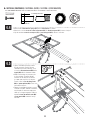
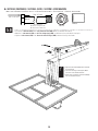
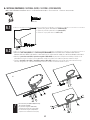
• Slide the axle (AJD) through one of the wheels (AMU) and into the base as indicated. Have one adult position the bottom pole
(ALE) within the base as shown (with the lip at the bottom of the pole facing outward). Finally, insert the axle through the bottom
pole and into the other side of the base and through the other wheel.
• Faire glisser l’essieu (AJD) à travers une des roues (AMU) et dans la base comme indiqué. Ensuite, un adulte doit positionner
le poteau inférieur (ALE) dans la base comme indiqué (avec le côté cabossé à l’extrémité intérieure du poteau vers l’extérieur). Insérer
l’essieu à travers le poteau inférieur, dans l’autre côté de la base, et à travers l’autre roue.
• Deslizar el eje (AJD) por una de las ruedas (AMU) y dentro de la base como se muestra. Entonces, un adulte debe ubicar el
poste inferior (ALE) dentro de la base como se muestra (con el lado abollado del poste inferior hacia afuera). Por último, insertar el
eje por el poste inferior y dentro del otro lado de la base y a través de la otra rueda.
• It may be necessary to use a rubber mallet to tap
the axle into place.
• Il peut-être nécessaire d’utiliser un maillet en
caoutchouc pour frapper l’essieu en place.
• Tal vez sea necesario usar un mazo de goma para
tapar el eje en su lugar.
AJD
AMU
AMU
ALE
!

14
TOOLS AND HARDWARE REQUIRED / OUTILS ET QUINCAILLERIE REQUIS / INSTRUMENTAL Y HERRAJE REQUERIDOS
SECTION 2 (CONTINUED) / SECTION 2 (SUITE) / SECCIÓN 2 (CONTINUACIÓN)
• Tip the system forward and rest the pole on the ground. Do not stand the system up until it is fi lled with either sand or water later in
the assembly. Tighten the hardware indicated.
• Faire basculer le système en avant et poser le poteau sur la terre. Ne pas remettre le système à la verticale jusqu’à ce qu’il soit
rempli d’eau ou de sable plus tard dans l’assemblage. Serrer la quincaillerie indiqué.
• Inclinar el sistema hacia delante y colocar el poste en el suelo. No poner vertical el sistema hasta llenarlo con agua o arena más
tarde en el ensamble. Apretar el herraje indicado.
2.5
2.4 • Attach the pole braces (ALI) to the bottom pole (ALE) with the hardware indicated.
• Attacher les supports du poteau (ALI) au poteau inférieur (ALE) à l’aide de la quincaillerie indiquée.
• Sujetar los soportes del poste (ALI) al poste inferior (ALE) usando el herraje indicado.
3/16 in/po (≈5 mm)
DRZ (x1) BTS (x1)
(x2)
BTS DRZ
ALE
ALI
ALI

15
BCS
Metal parts / Pièces en métal / Piezas de metal
PARTS REQUIRED / PIÈCES REQUISES / PIEZAS REQUERIDAS
HARDWARE REQUIRED / QUINCAILLERIE REQUISE / HERRAJE REQUERIDO
ABD (x2) ABF (x2)
AAM (x2)
ABK (x4)
AJW (x2) APZ (x1)
AOW (x1)
AAV (x2)
DFE (x4)
ABB (x4)
AAJ (x2)
AJI (x1)
ALX (x1)
ALD (x1)
DFD (x1)
AMY (x2)
Plastic parts / Pièces en plastique / Piezas de plástico
TOOLS REQUIRED / OUTILS REQUIS / HERRAMIENTAS REQUERIDAS
(x2) (x2) (x2)
7/16" (≈11 mm) 1/2" (≈13 mm) 9/16" (≈14 mm)
(x1)
BACKBOARD-TO-RIM ASSEMBLY / ASSEMBLAGE DU PANNEAU À L’ANNEAU / ENSAMBLAJE DEL TABLERO AL ARO
3

16
SECTION 3 (CONTINUED) / SECTION 3 (SUITE) / SECCIÓN 3 (CONTINUACIÓN)
TOOLS AND HARDWARE REQUIRED / OUTILS ET QUINCAILLERIE REQUIS / HERRAMIENTAS Y HERRAJE REQUERIDOS
• Insert two bolts (AAM) with washers (ABD) and rubber washers (ABF) through the holes
indicated in the back of the rim (ALX) as shown. Secure the hardware with two
T-nuts (AAJ).
• Insérer deux boulons (AAM) avec des rondelles (ABD) et des rondelles en caoutchouc
(ABF) à travers les trous dans la partie arrière de l’anneau (ALX) comme indiqué.
Fixer la quincaillerie à l’aide de deux écrous hexagonaux en « T » (AAJ).
• Insertar dos pernos (AAM) con rondanas (ABD) y rondanas de goma
(ABF) por los agujeros indicados en la parte posterior del aro (ALX)
como se muestra. Fijar el herraje con dos tuercas hexagonales en
« T » (AAJ).
• Ensure that the tap bolts (AAM) are positioned
on the outside edge of the holes as shown.
• Veiller à positionner les boulons (AAM) vers le
bord extérieur des trous comme indiqué.
• Asegurarse de ubicar los pernos (AAM) cerca el
borde exterior de los agujeros como se muestra.
• Do not overtighten the hardware so much that the rubber
washers bulge as shown.
• Ne pas serrer excessivement les accessoires pour que les
rondelles en caoutchouc se gonfl ent comme indiqué.
• No apretar demasiado el herraje para que las rondanas de
goma sobresalgan como se muestra.
!
!
1/2" (≈13 mm)
ABD (x2) ABF (x2)
AAM (x2)
ABF ABF
AAJ
AAM ABD ABF
ALX
AAM AAM
AAJ AAJ
AAJ (x2)
(x2)
(x1)
AAJ
AAM ABD ABF
3.1
• If you have trouble with this section, scan the code below to view a video on on its assembly.
• En cas d’avoir des problèmes avec cette section, scanner le QR code en dessous pour voir un vidéo de l’assemblage.
• En caso de tener problemas con esta sección, escanear el código QR debajo para ver un video del ensamblaje.
•
http://go.lifetime.com/actiongripsection3

17
SECTION 3 (CONTINUED) / SECTION 3 (SUITE) / SECCIÓN 3 (CONTINUACIÓN)
TOOLS AND HARDWARE REQUIRED / OUTILS ET QUINCAILLERIE REQUIS / HERRAMIENTAS Y HERRAJE REQUERIDOS
1/2" (≈13 mm)
3.2 • Connect the rim (ALX) and plastic guard (ALD) to the backboard (AJI) with the hardware shown.
• Attacher l’anneau (ALX) et le recouvrement protecteur en plastique (ALD) au panneau (AJI) à l’aide de la quincaillerie indiquée.
• Sujetar el aro (ALX) y el resguardo de plástico (ALD) al tablero (AJI) usando el herraje indicado.
APZ
ALX
ABK
ALD
AAM
ABK (x2)
AJI
DFD
APZ (x1)
(x2)

18
SECTION 3 (CONTINUED) / SECTION 3 (SUITE) / SECCIÓN 3 (CONTINUACIÓN)
TOOLS AND HARDWARE REQUIRED / OUTILS ET QUINCAILLERIE REQUIS / HERRAMIENTAS Y HERRAJE REQUERIDOS
AAV
ABK
AOW
AJW
APZ
3.3
3.4
• Turn the backboard assembly over. Thread the jam nuts (AAV) onto each end of the U-bolt (APZ) as far as they will
go. Slide the compression springs (AJW) onto the U-bolt, and place the spring retainer plate (AOW) over the compression
springs. Secure the plate to the springs with the hardware shown.
• Faire basculer le panneau. Visser les contre-écrous de (AAV) sur chaque extrémité du boulon en « u » (APZ) autant que
possible. Faire glisser les ressorts de compression (AJW) sur le boulon en « u », et mettre la plaque de retenue (AOW) sur
les ressorts de compression. Bien attacher la plaque aux ressorts à l’aide de la quincaillerie indiquée.
• Dar la vuelta el tablero. Apretar por completo las contratuercas (AAV) en el perno en «U». Deslizar los resortes de
compresión (AJW) en el perno en «u», y colocar la placa retenedor del resorte (AOW) sobre los resortes de compresión. Sujetar
la placa a los resortes usando el herraje indicado.
• Attach the backboard brackets (AMY) to the backboard using the hardware indicated.
• Bien attacher les supports du panneau (AMY) au panneau à l’aide de la quincaillerie indiquée.
• Sujetar los soportes del tablero (AMY) al tablero usando el herraje indicado.
AAV (x2) ABK (x2)
AJW (x2)
AOW (x1)
• DO NOT COMPLETELY TIGHTEN THE FLANGE NUTS IN THIS STEP! Only
tighten the nuts until the rim does not wobble. Tightening the nuts
will adjust the rim tension.
• NE PAS SERRER COMPLÈTEMENT LES ÉCROUS À BRIDE DANS CETTE
ÉTAPE! Seulement serrer les écrous jusqu’à ce que l’anneau ne soit
pas bancal. Serrer les écrous ajustera la tension de l’anneau.
• NO APRETAR POR COMPLETO LAS TUERCAS ACAMPANADAS EN ESTE
PASO! Sólo apretar las tuercas hasta que el aro no se bambolee.
Apretar las tuercas ajustará la tensión del aro.
DFE (x4)
ABB (x4)
ABB
DFE
DFE
DFE
DFE
ABB
AMY
7/16" (≈11 mm)
1/2" (≈13 mm)
9/16" (≈14 mm)
(x2)
!
9/16" (14 mm)
(x2)

19
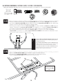
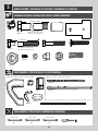
4BACKBOARD-TO-POLE ASSEMBLY / ASSEMBLAGE DU PANNEAU AU POTEAU / ENSAMBLAJE DEL TABLERO AL POSTE
7 5/8" (≈19,4 cm)
Metal parts / Pièces en métal / Piezas de metal
TOOLS REQUIRED / OUTILS REQUIS / INSTRUMENTAL REQUERID0
PARTS REQUIRED / PIÈCES REQUISES / PIEZAS REQUERIDAS
HARDWARE REQUIRED / QUINCAILLERIE REQUISE / HERRAJE REQUERIDO
(x2) (x2)
3/4" (≈19 mm) 9/16" (≈14 mm)
(x1)
BCR
AJY (x2)
AKC (x2)
AKB (x2)
AAX (x4)
ABB (x1)
AAD (x2)
GBU (x2)
DFC (x1)
7 1/16" (≈18 cm)
7 1/2”
HMP (x2)
ABN (x8)
7 1/2" (≈19 cm)

20
SECTION 4 (CONTINUED) / SECTION 4 (SUITE) / SECCIÓN 4 (CONTINUACIÓN)
TOOLS AND HARDWARE REQUIRED / OUTILS ET QUINCAILLERIE REQUIS / INSTRUMENTAL Y HERRAJE REQUERIDOS
• If you have trouble with this section, scan the code below to view a video on on its assembly.
• En cas d’avoir des problèmes avec cette section, scanner le QR code en dessous pour voir un vidéo de l’assemblage.
• En caso de tener problemas con esta sección, escanear el código QR debajo para ver un video del ensamblaje.
•
http://go.lifetime.com/actiongripsection4
AAX (x1)
ABN (x2)
3/4" (≈19 mm) (x2)
GBU (x1)
7 5/8" (≈19,4 cm)
4.1 • Attach the short extension arms (AKC) to the backboard brackets in the location shown with the hardware indicated.
Secure only by hand at this point.
• Attacher les bras de rallonge courts (AKC) aux supports du panneau à l’emplacement indiqué à l’aide de la
quincaillerie indiquée. Serrer la quincaillerie à la main en ce moment.
• Sujetar los brazos de extensión cortos (AKC) a los soportes del tablero a la ubicación indicada usando el herraje
indicado. Apretar el herraje sólo a mano en este momento.
AKC AKC
AAX ABN
ABN
HMP
• A centerlock nut requires some effort to thread onto a
bolt. See page 4 for details.
• Un écrou de blocage central exigera un certain effort
pour le serrer sur un boulon. Voir la page 4 pour
obtenir plus de détails.
• Una tuerca de bloqueo central requerirá un poco de
esfuerzo para enroscarlo en el perno. Ver la página 4
para más detalles.
• If necessary, use a bolt to remove any
excess powder coating from the holes in the
backboard brackets.
• Si nécessaire, utiliser un boulon pour enlever
l’excès de couche de peinture en poudre des
trous dans les supports du panneau.
• Si es necesario, utilizar un tornillo para sacar
el exceso de recubrimiento en polvo de los
huecos de los soportes de tablero.
!
GBU
• DO NOT strike this bolt (GBU) with a mallet! If there is diffi culty sliding the bolt into place,
use a wrench to turn the bolt until it has advanced into position.
• NE PAS frapper le boulon (GBU) avec un maillet! S’il y a diffi culté à faire glisser le boulon
en place, utiliser une clé pour tourner le boulon jusqu’à ce qu’il s’emboîte en place.
• ¡NO golpear el perno (GBU) con un mazo! Si hay difi cultad deslizando el perno en su lugar,
usar una llave para rotar el perno hasta que se encaje en su lugar.
!
HMP (x1)
La page est en cours de chargement...
La page est en cours de chargement...
La page est en cours de chargement...
La page est en cours de chargement...
La page est en cours de chargement...
La page est en cours de chargement...
La page est en cours de chargement...
La page est en cours de chargement...
La page est en cours de chargement...
La page est en cours de chargement...
La page est en cours de chargement...
La page est en cours de chargement...
La page est en cours de chargement...
La page est en cours de chargement...
La page est en cours de chargement...
La page est en cours de chargement...
La page est en cours de chargement...
La page est en cours de chargement...
La page est en cours de chargement...
La page est en cours de chargement...
La page est en cours de chargement...
La page est en cours de chargement...
La page est en cours de chargement...
La page est en cours de chargement...
La page est en cours de chargement...
La page est en cours de chargement...
La page est en cours de chargement...
La page est en cours de chargement...
-
 1
1
-
 2
2
-
 3
3
-
 4
4
-
 5
5
-
 6
6
-
 7
7
-
 8
8
-
 9
9
-
 10
10
-
 11
11
-
 12
12
-
 13
13
-
 14
14
-
 15
15
-
 16
16
-
 17
17
-
 18
18
-
 19
19
-
 20
20
-
 21
21
-
 22
22
-
 23
23
-
 24
24
-
 25
25
-
 26
26
-
 27
27
-
 28
28
-
 29
29
-
 30
30
-
 31
31
-
 32
32
-
 33
33
-
 34
34
-
 35
35
-
 36
36
-
 37
37
-
 38
38
-
 39
39
-
 40
40
-
 41
41
-
 42
42
-
 43
43
-
 44
44
-
 45
45
-
 46
46
-
 47
47
-
 48
48


Lifetime 90176 Le manuel du propriétaire
- Taper
- Le manuel du propriétaire
dans d''autres langues
- English: Lifetime 90176 Owner's manual
- español: Lifetime 90176 El manual del propietario
Documents connexes
-
Lifetime 90176 Le manuel du propriétaire
-
-
-
-
-
-
-
-
-