Installation:
1. Turn power OFF from the electrical panel prior to installation.
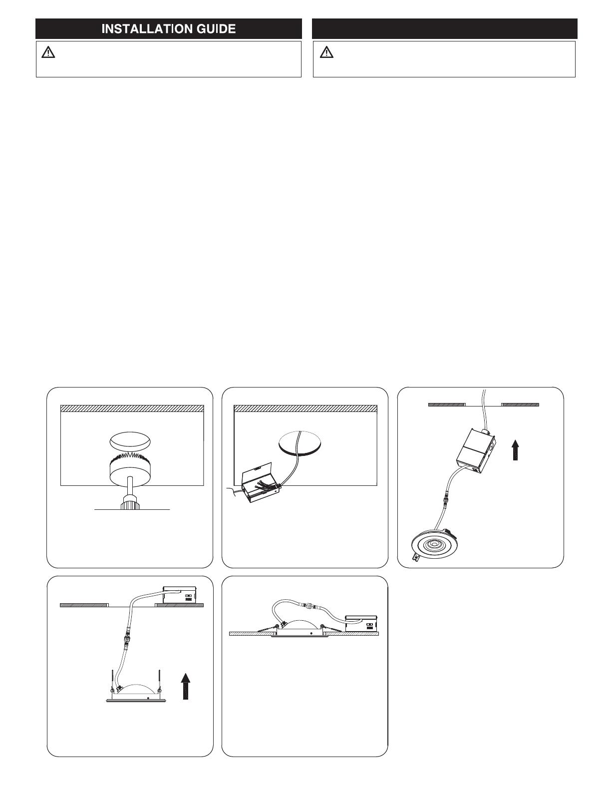
2. Determine the location for installation and cut ceiling hole in
accordance with cut-hole dimensions. Refer to Installation Hole
Size for cutting hole diameters. (Fig. 1)
3. Insert the electrical cable through the knockout of the remote
driver, and secure it with a cable connector.
4. Strip 1/3” (8mm) of the insulation off each incoming 120V power
wire. Connect white wire (neutral) to the white wire from remote
driver. Connect black incoming 120V power wire (hot wire) to the
black wire from remote driver. Connect ground wire to the ground
wire of the remote driver. (Fig. 2)
5. Place all wiring and connections back in to the box and close the
cover. Connect the driver to the light panel.
6. Insert remote driver through the mounting hole. (Fig. 3)
7. Secure the junction box in the ceiling with the screws provided.
8. Push spring-loaded clips on the xture upwards and insert xture
base in to the mounting hole. Release the clips and xture will be
pulled ush to the ceiling. (Fig. 4-5)
NOTE: Use packaging inside box as installation hole cutting
template to mount the xture in the ceiling.
Installation:
1. Coupez l’électricité à partir du panneau électrique avant de
commencer l’installation.
2. Déterminez un endroit approprié pour l’encastré. Mesurez et
coupez un trou conformément aux dimensions coupe-trous.
Reportez-vous à la taille des trous d’installation pour les diamètres
des trous. (Fig. 1)
3. Insérez le câble d’alimentation électrique par la provision du
commande à distance, et le xer avec un connecteur de câble.
4. Dénuder 1/3 po (8 mm) d’isolation de chaque l d’entrée de
courant de 120 volts. Brancher le l blanc (neutre) au l blanc
venant du commande à distance. Brancher le l noir d’entrée
de courant de 120 volts (l sous tension) au l noir venant du
commande à distance. Brancher le l de mise à la terre au l de
mise à la terre relié à la commande à distance. (Fig. 2)
5. Placez tout le câblage et les connexions dans la boîte et fermez le
couvercle. Branchez le circuit et le luminaire.
6. Insérez la commande à distance à travers le trou de montage. (Fig. 3)
7. Fixez la boîte de jonction dans le plafond avec les vis fournies.
8. Pousser les clavettes du luminaire vers le haut et insérez la base
de l’appareil dans le trou de montage. Relâchez les clavettes et
l’appareil sera tiré au ras du plafond. (Fig. 4-5)
REMARQUE: utilisez l’emballage à l’intérieur de la boîte
comme gabarit de trou d’installation pour monter le luminaire
au plafond.
Disconnect power before installation or maintenance.
WARNING
Débrancher l'alimentation avant l'installation ou l'entretien.
MISE EN GARDE
GUIDE D'INSTALLATION
Disconnect power before installation or maintenance.
WARNING
Débrancher l'alimentation avant l'installation ou l'entretien.
MISE EN GARDE
GUIDE D'INSTALLATION
Step 1 Step 2 Step 3
Step 4 Step 5
Installation hole sizes:
3” = 85mm (3 3/8”)
4” = 112mm (4 7/16”)
6” = 153mm (6”)

