
Instructions AIPB DN 15 - 50
6 000 005 880 DEBC 10 / 01 VI.CA.Z1.5V 1
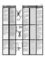
Differential Pressure Controller
with Flow Limitation AIPB
ENGLISH
Page 2
www.danfoss.com
AIPB
2
www.danfoss.ru
POLSKI
Regulator ró nicy ci nie AIPB
Strona 2
www.danfoss.pl
DEUTSCH
Differenzdruckregler mit
Durchflussbegrenzung AIPB
Seite 2
www.iwk.danfoss.de
FRANCAIS
Régulateur de pression différentielle
avec limitation du débit AIPB
Page 2
www.danfoss.fr

Type AIPB
ENGLISH DEUTSCH
2
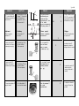
Contents
Sicherheitshinweise 3
Einbau 4
-Steuerleitungsanschluß 5
-Abmessungen 6
Inbetriebnahme 7
-Dichtheitsprüfung /
Druckprüfung 7
-Differenzdruck-
einstellung 8
-Einstellung
Volumenstrom-
begrenzung 10
Hilfe 12
POLSKI
Spis tre ci
Warunki
bezpiecze stwa 3
Monta 4
- Przy cze przewodu
impulsowego 5
- Wymiary 6
Uruchomienie 7
- Próby ci nieniowe i
szczelno ci 7
- Nastawa ró nicy
ci nie 8
- Nastawa ograniczenia
przep ywu 10
Contents
Safety Notes 3
Installation 4
- Control line
connection 5
- Dimensions 6
Start up 7
- Leak and pressure
tests 7
- Differential pressure
settings 8
- Setting or Flow Rate
Limitation 10
Help 11
3
4
-
5
-
6
7
-
7
-
8
-
10
FRANCAIS
Sommaire
Consignes de sécurité 3
Montage 4
- Raccordement
conduite de
commande 5
- Dimensions 6
Mise en service 7
- Contrôle d’étanchéité
et de pression 7
- Réglage de la
pression différentielle 8
- Réglage de la
limitationdu débit 10

Type AIPB
ENGLISH DEUTSCH
3
Sicherheitshinweise
Um Verletzungen an Perso-
nen und Schäden am
Stellantrieb zu vermeiden,
diese Anleitung unbedingt
beachten.
Montage, Inbetriebnahme
und Wartungsarbeiten
dürfen nur von sach-
kundigen und autorisierten
Personen durchgeführt
werden.
Vor Montage - und
Wartungsarbeiten am
Regler muß die Anlage
drucklos
ausgekühlt
geleert
und gereinigt sein
Die Vorgaben des
Anlagenherstellers bzw.
Anlagenbetreibers sind zu
beachten.
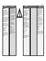
Safety Notes
Prior to assembly and
commissioning, these
Assembly, Start-up, and
Maintenance Instructions
must be read carefully and
observed.
Necessary assembly, start-
up, and maintenance work
must only be performed by
qualified, trained, and
authorized personnel.
Prior to assembly and
maintenance work on the
controller, the system must
be:
depressurized,
cooled down,
emptied
and cleaned.
Please comply with the
instructions of the system
manufacturer or system
operator.
POLSKI
Warunki bezpiecze stwa
W celu unikni cia ryzyka
zranienia osób i
uszkodzenia urz dze
nale y bezwzgl dnie i
wnikliwie zapozna si z
niniejsz instrukcj .
Niezb dny monta ,
uruchomienie oraz obs uga
mog by dokonywane
wy cznie przez
wykwalifikowany i
autoryzowany personel.
Przed monta em i
konserwacj regulatora
musimy przeprowadzi
nast puj ce czynno ci na
uk adzie:
zrzuci ci nienie,
wych odzi ,
opró ni ,
oczy ci .
Prosimy stosowa si do
instrukcji producenta i/lub
operatora uk adu.
.
,
,
.
,
,
,
.
.
FRANCAIS
Consignes de sécurité
Lire attentivement cette
notice pour éviter tout
risque de blessure du
personnel ou de
détérioration de l’unité de
régulation.
Le montage, la mise en
route et les travaux
d’entretien doivent être
effectués par du personnel
qualifié et autorisé.
Avant tout montage ou
entretien sur le régulateur,
l’installation doit être :
sans pression
refroidie
vidée
et nettoyée
Respecter les consignes
du fabricant de l’installation
et de l’exploitant de celle-ci.

Type AIPB
ENGLISH DEUTSCH
4
·
.
·
.
·
.
·
.
·
100 °C
.
·
.
·
.
·
,
.
Einbau
· Vor der Montage ist das
Rohrleitungssystem zu
reinigen.
· Der Einbau eines
Schmutzfängers vor dem
Regler wird dringend
empfohlen.
· Druckanzeigen sind vor
und nach der zu
regelnden Anlagen-
strecke einzubauen.
· Der Regler muß im
Rücklauf eingebaut
werden.
· Die Einbaulage des
Reglers ist bis zu
Mediumstemperaturen
von 100°C beliebig.
· Bei höheren
Temperaturen muß der
Antrieb nach unten
hängend eingebaut
werden.
· Mechanische
Belastungen des
Ventilgehäuses durch die
Rohrleitungen sind nicht
zulässig.
· Die Durchflußrichtung auf
dem Typenschild muß
beachtet werden
Installation
· Clean pipeline system
prior to assembly.
· The installation of a
strainer in front of the
controller is strongly
recommended.
· Install pressure
indicators in front of and
behind the system part to
be controlled.
· The controller must be
installed in the return
pipe.
· Up to a medium
temperature of 100 °C the
controllers may be
installed in any position.
· For higher temperatures,
the actuator must be
installed in a downward
hanging position.
· Mechanical loads of the
valve body by the
pipelines are not
permitted.
· The flow direction
indicated on the product
label must be followed.
POLSKI
Monta
· Przed monta em oczy ci
ruroci g.
· Zalecany jest monta filtra
przed regulatorem.
· Zamontowa manometry
przed i za regulatorem.
· Regulator mo na
montowa na ruroci gu
zasilaj cym lub
powrotnym.
· Pozycja monta u
regulatora dla temperatury
medium do 100
0
C jest
dowolna.
· Przy wy szych
temperaturach nap d
musi by skierowany ku
do owi.
· Obci enia mechaniczne
korpusu zaworu przez
ruroci gi s
niedopuszczalne.
· Nale y przestrzega
kierunku przep ywu na
tabliczce znamionowej.
FRANCAIS
Montage
· Nettoyer la tuyauterie
avant le montage
· Il est vivement conseillé
de monter un filtre devant
le régulateur
· Monter des manomètres
avant et après le
régulateur
· Le régulateur doit être
monté dans le retour
· L’orientation de montage
du régulateur est au choix
pour des températures
de fluide jusqu’à 100°C
· Avec des températures
plus élevées le moteur
doit être monté vers le
bas
· Des charges
mécaniques sur le corps
de vanne par la tuyauterie
ne sont pas admises
· Respecter le sens
d’écoulement sur la
plaque signalétique

Type AIPB
ENGLISH DEUTSCH
5
· :
.
.
,
.
·
.
.
· (+)
(
Ø6 x 1) (+)
À.
· AIPB
.
À
· Achtung:
Das Ventil mit
angeschraubten
Anschweißenden darf in
der Rohrleitung nur
angeheftet werden.
Das Einschweißen der
Anschweißenden ist nur
ohne Ventil und
Dichtungen zulässig.
Bei Nichtbeachtung
zerstören die hohen
Schweißtemperaturen die
Dichtungen des Ventils.
Steuerleitungsanschluß
· Es wird empfohlen den
Steuerleitungsanschluß
an der Rohrleitung
waagrecht anzubringen.
Verschmutzungen in der
Steuerleitung und mög-
liche Funktionsstörungen
des Reglers werden
dadurch vermieden.
· Die Steuerleitung (Cu-
Rohr Ø6x1) ist am (+)
Anschluß des Antriebes
und vor der zu regelnden
Anlagenstrecke
anzuschließen À.
· Der Regler AIPB ist nur
für den Einbau im
Rücklauf vorgesehen.
· Caution:
The valve with mounted
screwed welded ends
must only be pinned to
the pipeline.
The welded ends must
only be welded without
the valve and seals!
If these instructions are
not complied with, high
welding temperatures
may destroy the seals.
Control line connection
· We recommend to install
the control line to the
pipeline in an upright or
horizontal position.
This avoids dirt in the
control line and possible
malfunction of the
controller.
· Connect the (+)control
line (Cu pipe Ø6 x 1) to
the (+)connection of the
actuator and in front of the
system part to be
controlled À.
· The controller AIPB is
only to be installed in the
return side.
POLSKI
· Uwaga:
Zawór z przykr canymi
ko cówkami do spawania
mo emy tylko lekko
zgrza .
Ko cówki do spawania
mog by przyspawane
po wyj ciu zaworu i
uszczelek.
Nie podporz dkowanie
si zaleceniom mo e
doprowadzi do tego, e
wysoka temperatura
zniszczy uszczelnienia.
Przy cze przewodu
impulsowego
· Zaleca si umieszczenie
na ruroci gu przy czy
przewodu impulsowego
skierowanych w gór lub
poziomo.
Unika si w ten sposób
zanieczyszcze w
przewodach impulsowych
i ewentualnych zak óce
funkcjonalnych
regulatora.
· Przewód impulsowy (+)
(rurka miedziana CuØ
6x1) naleýy doprowadzi
do przy cza (+) nap du
przed regulowanym
odcinkiem instalacji À.
· Regulator AIPB mo e by
montowany tylko na
ruroci gu powrotnym.
FRANCAIS
· Attention :
La vanne, avec embouts
à souder vissés sur le
corps, doit uniquement
être soudée par points
dans la tuyauterie.
La soudure des embouts
à souder est uniquement
autorisée sans la vanne
et les joints.
En cas de non-respect,
les températures élevées
de soudure détériorent
les joints de la vanne
Raccordement conduite de
commande
· Il est conseillé de fixer le
raccordement de la
conduite de commande,
horizontalement sur la
tuyauterie
Cela permet d’éviter
l’encrassement dans la
conduite de commande
et de possibles
perturbations de
fonctionnement du
régulateur.
· La conduite de
commande (+) (tube Cu
Ø6x1) doit être raccordée
au branchement (+) du
moteur et devant le
régulateur À.
· Le régulateur AIPB est
uniquement prévu pour
un montage dans le
retour.

Type AIPB
ENGLISH DEUTSCH
6
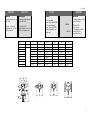
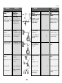
DN 15 20 25 32 40 50
R
À
R ½ R ¾ R 1
d 21 26 33 424860
SW 32 (G¾A) 41 (G1A) 50 (G1¼A) 63 70 82
E 65 70 75 100 110 130
L mm 139 154 159 184 204 234
L1 125 146 169
L2
Á
130 150 160 180 200 230
H1 57 64 64 95 100 100
H2 210 216 216 246 250 250
À Kegeliges Außengewinde
nach DIN 2999
Á Flansche PN 25:
Anschlußmaße nach DIN
2501, Dichtleiste Form C
À Conic male thread acc. to
DIN 2999
Á Flanges: Connection
dimensions acc. to DIN
2501, seal form C
À
DIN 2999.
Á :
DIN 2501,
.
AbmessungenDimensions
Ø
POLSKI
Wymiary
À Sto kowy gwint
zewn trzny wg DIN 2999
Á Ko nierze: Wymiary
przy cza wg DIN 2501,
listwa uszczelniaj ca o
kszta cie C
FRANCAIS
Dimensions
À
Filetage extérieur conique
selon DIN 2999
Á
Brides PN25 :
Dimensions
raccordement à brides
selon DIN 2501,
étanchéité forme C

Type AIPB
ENGLISH DEUTSCH
7
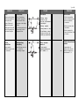
Start-up
À Open any shut-off valves
that may be installed in
the impulse tube.
Á Open all valves and
fittings in the system.
 Slowly open the shut-off
units in the supply flow
and return flow pipes.
Leak and
Pressure Tests
Pressure must be
constantly increased at the
+/– connection Ã
À ,
.
Á
.
Â
.
«+/-»
Ã
.
Inbetriebnahme
À In der Steuerleitung
eventuell vorhandene
Absperrventile öffnen.
Á Armaturen in der Anlage
öffnen.
 Die Absperrarmaturen im
Vorlauf und Rücklauf
langsam öffnen.
Dichtheitsprüfung /
Druckprüfung
Druckerhöhung muss am
+ / - Anschluss Ã
gleichmässig erfolgen
POLSKI
Uruchomienie
À Otworzy zawory
odcinaj ce, gdy
wyst puj w przewodach
impulsowych.
Á Otworzy wszystkie
zawory i armatur uk adu
 Powoli otworzy zawory
odcinaj ce na ruroci gu
zasilaj cym i powrotnym
Próba ci nieniowa i
szczelno ci
Ci nienie musi by
stopniowopodnoszone na
pod czeniach + i -.
Ã
Á
À
À
Ä
FRANCAIS
Mise en service
À Ouvrir les éventuelles
vannes d’arrêt présentes
dans la conduite de
commande
Á Ouvrir les vannes dans
l’installation
 Ouvrir lentement les
vannes d’arrêt dans l’aller
et le retour
Contrôle d’étanchéité et de
pression
L’augmentation de
pression doit se faire de
manière homogène aux
raccordements +/- Ã

Type AIPB
ENGLISH DEUTSCH
8
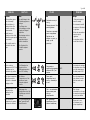
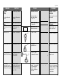
Set-point
Setting
First set the differential
pressure.
Differential Pressure
Setting
Set-point range see rating
plate À
1.Unscrew cap Á.
2. Loosen counter nut Â.
3.Unscrew adjusting
throttle
à up to its stop.
4.Start system,
see section “Start-up“
Completely open all shut-
off devices in the system.
Einstellung Sollwerte
Zuerst den Differenzdruck
einstellen
Einstellung Differenzdruck
Sollwertbereich siehe
Typenschild À
1.Kappe Á abschrauben
2.Kontermutter  lösen
3.Einstelldrossel à bis
zum Anschlag
herausdrehen
4.Anlage in Betrieb
nehmen, siehe Abschnitt
„Inbetriebnahme“ Alle
Armaturen in der Anlage
ganz öffnen
,
À
1. Á
2. Â.
3.
Ã.
4. , .
« ».
.
POLSKI
Zadawanie nastaw
W pierwszej kolejno ci
nale y zada nastaw
ró nicy ci nie .
Nastawa regulowanej
ró nicy ci nie .
Zakres nastaw patrz
tabliczka znamionowa
À
1. Odkr ci os on Á
2. Poluzowa
przeciwnakr tk Â.
3. Wykr ci d awik
nastawczy
à do oporu.
4. Uruchomi uk ad patrz
rozdzia Uruchomienie .
Ca kowicie otworzy
wszelk armatur
d awi c przep yw w
uk adzie.
Á
Â
Ã
À
p
S
0,1
–
1 bar
FRANCAIS
Réglage points de
consigne
D’abord régler la pression
différentielle
Réglage de la pression
différentielle
Plage de réglage, voir
plaque signalétique À
1. Dévisser le capuchon Á
2. Défaire le contre-écrou
Â
3. Dévisser le limiteur Ã
jusqu’en butée
4. Mettre l’installation en
service, voir paragraphe
«mise en service». Ouvrir
entièrement toutes les
vannes dans
l’installation.

Type AIPB
ENGLISH DEUTSCH
9
5.Volumenstrom an einer
Armatur
À, über welche
der Differenzdruck
geregelt wird, auf ca.
50% einstellen
Á.
6.Einstellung
Druckanzeigen Â
beachten.
Rechtsdrehung à er-
höht den Sollwert
(Feder spannen).
Linksdrehung Ä redu-
ziert den Sollwert
(Feder entspannen).
Der Sollwertsteller Å
kann plombiert werden.
POLSKI
5. Przy pomocy zaworu À
zamontowanego na
odcinku na którym
regulowana jest ró nica
ci nie , ustawi
przep yw na poziomie ok
50% przep ywu max. Á.
6. Dokona regulacji
obserwuj c wskazania
manometrów
Â.
Kr ci w prawo à w
celu zwi kszenia
warto ci nastawy
( ciskanie spr yny)
Kr ci w lewo Ä w celu
zmniejszenia warto ci
nastawy (luzowanie
spr yny)
Nakr tka nastawcza Å
mo e zosta
zaplombowana.
5.
À
50%
Á.
6.
Â.
Ã
.
Ä
.
Å
.
5.Set flow rate at a fitting
À, by which differential
pressure is controlled, to
about 50 %
Á.
6.Adjustment
Observe pressure
indicators
Â.
Turning to the right Ã
increases the set-point
(stressing the spring).
Turning to the left Ä
reduces the set-point
(unstressing the spring).
The set-point adjuster Å
may be sealed.
Dp
0 50%
V
max
Á
À
Â
Ä
Ã
FRANCAIS
5. Régler le débit à environ
50% Á sur une vanne À
par laquelle la pression
différentielle est réglée
6. Réglage
Observer les indications
de pression Â
La rotation à droite Ã
augmente la valeur de
consigne (tendre le ressort)
La rotation à gauche Ä
réduit la valeur de
consigne (détendre le
ressort)
Le régleur de valeur de
consigne Å peut être
plombé

Type AIPB
ENGLISH DEUTSCH
10
Einstellung
Volumenstrom-
begrenzung
Voraussetzung
Die Anlage muss in Be-
trieb sein. Armaturen in der
Anlage À müssen
vollständig offen sein.
1.Anzeige des
Wärmezählers beachten
Linksdrehung
 erhöht
den Volumenstrom
Rechtsdrehung à redu-
ziert den Volumenstrom
Nach abgeschlossener
Einstellung:
2.Kontermutter Ä fest-
ziehen
3.Kappe Å aufschrauben
4.Kappe kann plombiert
werden
POLSKI
Nastawa ograniczenia
przep ywu
Warunki wst pne
Uk ad musi by w czony.
Wszystkie urz dzenia w
uk adzie À musz by
ca kowicie otwarte.
1. ledzi wskazania
licznika ciep a.
Kr ci w lewo  w celu
zwi kszenia wielko ci
przep ywu.
Kr ci w prawo à w
celu redukcji wielko ci
przep ywu.
Po dokonaniu nastawy
nale y:
2. Dokr ci
przeciwnakr tk
Ä.
3. Nakr ci os on
Å.
4. Os ona mo e zosta
zaplombowana.
:
.
À
.
1.
.
Â,
.
Ã,
:
2.
Ä.
3. Å
4.
.
Setting of Flow Rate-
Limitation
Pre-condition:
The system must run. All
units in the system
À must
be completely open.
1.Observe heat meter
indicator.
Turning to the left
Â
increases the flow rate.
Turnung to the rightÃ
reduces the flow rate.
When the adjustment is
completed:
2.Tighten counter nut
Ä.
3.Place cap nut Å
4.Cap may be sealed
Â
Ä
Å
Ã
À
FRANCAIS
Réglage de la limitation du
débit
Condition :
L’installation doit être en
service. Les vannes dans
l’installation
À doivent être
entièrement ouvertes
1. Observer l’indication du
compteur thermique
La rotation à gauche Â
augmente le débit
La rotation à droite à réduit
le débit
Après avoir effectué le
réglage :
2. Serrer le contre-écrou Ä
3. Revisser le capuchon Å
4. Le capuchon peut être
plombé

Type AIPB
600 073 044 DEBC 08 / 01 VI.CA.Z1.5V 11
ENGLISH
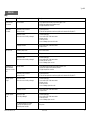
Help
Fault Possible cause Remedy
Set max. flow rate Air in the actuator 1. Loosen impulse tube connection on the actuator by approx. 1 turn.
is inconsistent. 2. Ventilate (move impulse tube until medium escapes).
3. Re-tighten impulse tube connections.
Set flow rate Impulse tube or their connections 1. Dismount impulse tube.
is exceeded. are dirty or blocked. 2. Check and clean impulse tube connections on pipeline and on actuator with orifice plate Ø 1.
Valve does not close: 1. Remove impulse tubes.
Valve seat or cone unit is dirty or damaged. 2. Loosen union nut SW 36 and remove actuator.
3. Unscrew cone unit.
4. Clean seat and cone.
5. In case of damage, replace cone unit or valve.
Diaphragm is defective. 1. Loosen union nut SW 36 and remove actuator.
2. Replace actuator.
Flow rate too low Limitation by output control Check the control function.
Differential pressure is too low Check system.
Valve does not open: 1. Remove impulse tubes.
Valve seat or cone unit is dirty or damaged. 2. Loosen union nut SW 36 and remove actuator.
3. Unscrew and clean cone unit.
4. In case of damage, replace cone unit.
Controller does not Air in the actuator 1. Loosen impulse tube connections on the actuator by approx. 1 turn.
keep the differential 2. Ventilate (move impulse tube until medium penetrates).
pressure on a constant 3. Re-tighten impulse tube connections.
level.
Impulse tube or their connections 1. Dismount impulse tube.
are dirty or blocked. 2. Check and clean impulse tube connections on pipeline and on actuator with orifice plate Ø 1.
Differential pressure Valve does not close: 1. Remove impulse tubes.
too high Valve seat or cone unit is dirty or damaged. 2. Loosen union nut SW 36 and remove actuator.
3. Unscrew cone unit.
4. Clean seat and cone.
5. In case of damage, replace trim or valve.
Diaphragm is defective. 1. Loosen union nut SW 36 and remove actuator.
2. REplace actuator.
Differential pressure Valve does not open: 1. Remove impulse tubes.
too low Cone is dirty or damaged. 2. Loosen union nut SW 36 and remove actuator.
3. Clean seat and cone.
4. In case of damage, replace cone unit.
The differential pressure in the system
is lower than the setpoint set on the Check system.
differential pressure controller.

Type AIPB
600 073 044 DEBC 08 / 01 VI.CA.Z1.5V 12
DEUTSCH
Störung Mögliche Ursache Maßnahme
Eingestellter max. Luft im Antrieb 1. Steuerleitungsanschlüsse am Antrieb ca. 1 Umdrehung lösen
Volumenstrom 2. Entlüften (Steuerleitung bewegen bis Medium austritt)
ist nicht konstant 3. Steuerleitungsanschlüsse wieder anziehen
Eingestellter Steuerleitung bzw. Steuerleitungsanschlüsse am 1. Steuerleitung demontieren
Volumenstrom Antrieb mit Blende verschmutzt oder verstopft 2. Steuerleitung, Anschlüss am Antrieb mit Blende Ø 1 reinigen und Durchgang überprüfen
wird überschritten
Ventil schließt nicht: 1. Steuerleitungen abbauen
Ventilsitz, Kegel oder Innengarnitur 2. Überwurfmutter SW 36 lösen und Antrieb abnehmen
verschmutzt oder beschädigt 3. Innengarnitur herausschrauben
4. Sitz und Kegel reinigen
5. Bei Beschädigung Innengarnitur bzw. Ventil austauschen
Membrane defekt 1. Überwurfmutter SW 36 lösen und Antrieb abnehmen
2. Antrieb austauschen
Volumenstrom zu niedrig Begrenzung durch Leistungsregelung Regelung überprüfen
Diffenrenzdruck zu niedrig Differenzdruckeinstellung überprüfen.
Ventil öffnet nicht: 1. Steuerleitungen abbauen
Ventilsitz, Kegel oder Innengarnitur 2. Überwurfmutter SW 36 lösen und Antrieb abnehmen
verschmutzt oder beschädigt 3. Innengarnitur herausschrauben und reinigen
4. Bei Beschädigung Innengarnitur austauschen
Regler hält den Luft im Antrieb 1. Steuerleitungsanschlüsse am Antrieb ca. 1 Umdrehung lösen
Differenzdruck 2. Entlüften (Steuerleitung bewegen bis Medium austritt)
nicht konstant 3. Steuerleitungsanschlüsse wieder anziehen
Steuerleitung bzw. Steuerleitungsanschlüsse am 1. Steuerleitung demontieren
Antrieb mit Blende verschmutzt oder verstopft 2. Steuerleitung, Anschlüss am Antrieb mit Blende Ø 1 reinigen und Durchgang überprüfen
Differenzdruck zu hoch Ventil schließt nicht: 1. Steuerleitungen abbauen
Ventilsitz, Kegel oder Innengarnitur 2. Überwurfmutter SW 36 lösen und Antrieb abnehmen
verschmutzt oder beschädigt 3. Innengarnitur herausschrauben
4. Sitz und Kegel reinigen
5. Bei Beschädigung Innengarnitur bzw. Ventil austauschen
Membrane defekt 1. Überwurfmutter SW 36 lösen und Antrieb abnehmen
2. Antrieb austauschen
Differenzdruck zu niedrig Ventil öffnet nicht: 1. Steuerleitungen abbauen
Innengarnitur verschmutzt oder beschädigt 2. Überwurfmutter SW 36 lösen und Antrieb abnehmen
3. Innengarnitur herausschrauben und reinigen
4. Bei Beschädigung Innengarnitur austauschen
Der Differenzdruck über der Anlage ist geringer als Anlage überprüfen
der am Differenzdruckregler eingestellte Sollwert
Hilfe
-
 1
1
-
 2
2
-
 3
3
-
 4
4
-
 5
5
-
 6
6
-
 7
7
-
 8
8
-
 9
9
-
 10
10
-
 11
11
-
 12
12


dans d''autres langues
- English: Danfoss AIPB Operating instructions
- Deutsch: Danfoss AIPB Bedienungsanleitung
- polski: Danfoss AIPB Instrukcja obsługi