
11/2023
Read these instructions carefully before using your appliance, and keep it carefully.
If you follow the instructions, your appliance will provide you with many years of good service.
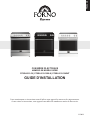
MODEL NUMBER SERIES
FFSEL6012-30 | FFSEL6012-30BLK | FFSEL6012-30WHT
INSTALLATION GUIDE
ELECTRIC RANGE
ENGLISH

2
TABLE OF CONTENTS
Range Safety 4
Tools and Parts 6
Installation Requirements 7
Electrical Requirements - U.S.A. Only 9
Electrical Requirements - Canada Only 9
Step 1 - Unpack Range 10
Step 2 - Install Anti-Tip Bracket 11
Step 3 - Make Electrical Connection 12
Step 4 - Install Range 19
Step 5 - Complete Installation 20

3
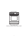
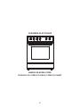
MODEL NUMBER SERIES
FFSEL6012-30 | FFSEL6012-30BLK | FFSEL6012-30WHT
ELECTRIC RANGE

4
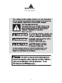
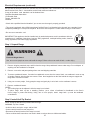
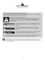
WARNING
FOR YOUR SAFETY

5
WARNING
FOR YOUR SAFETY
State of California Proposition 65 Warnings:
WARNING: This product contains one or more chemicals known to the State of California to
cause cancer.
WARNING: This product contains one or more chemicals known to the State of California to
cause birth defects or other reproductive harm.

6
Tools and Parts
Location Requirements
Check
Box Tools
Tape Measure
Flat-Blade Screwdriver
Phillips Screwdriver
Level
Cordless Electric Drill
Hammer
Wrench or Pliers
Metal Saw
Metal Snips or Large Wire Cutters
15/N6” Combination Wrench
3/8” Nut Driver
1/4” Nut Driver
1/8” (3.2 mm) Drill Bit (for wood
Marker or Pencil
Masking Tape
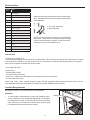
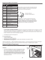
A: 16 x 15/8” Screws (2)
B: Anti-tip Bracket
A
B
NOTE: The Anti-tip bracket must be securely mounted to
available from your local hardware store.
Parts Needed:
If using a power supply cord:
• A UL listed power supply cord kit marked for use with ranges. The cord should be rated at 250 volts minimum, 40 amps
or 50 amps that is marked for use with nominal 13/8” (3.5 cm) diameter connection opening and must end in ring termi-
nals or open-end spade terminals with upturned ends.
• A UL listed strain relief.
If direct wiring:
• Flexible Metal Conduit
• UL Listed Conduit Connector
• 4-wire or 3- ire Electrical Cable (where local codes permit a 3-wire connection).
• UL Listed Wire Connectors
Check local codes. Check existing electrical supply. See the appropriate “Electrical Requirements” section. It is rec-
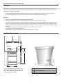
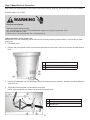
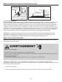
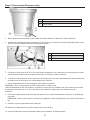
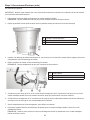
Ventilation
• It is the installer’s responsibility to comply with installation clear-
-
rial rating plate is located on the left-hand side of the oven frame.
Open oven door to view label. See label on back panel of range
for additional element and oven power ratings.
Rating Plate
Gather the required tools and parts before starting instal-
lation. Read and follow the instructions provided with any
tools listed here.
IMPORTANT: Observe all governing codes and ordinances.

7
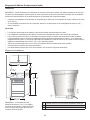
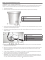
Location Requirements (continued)
Installation Requirements
A Access Panel to Electrical Supply Connection
B Power Cord Opening
CRecessed Area
Temperature
IMPORTANT: Some cabinet and building materials are not designed to withstand the heat produced by the oven for bak-
ing and self-cleaning. Check with your builder or cabinet supplier to make sure that the materials used will not discolor,
delaminate or sustain other damage.
•
• Use an insulated pad or 1/4” (0.64 cm) plywood under range if installing range over carpeting.
General
• The range should be located for convenient use in the kitchen.
• Recessed installations must provide complete enclosure of the sides and rear of the range.
•
surface units should be avoided. If cabinet storage is to be provided, the risk can be reduced by installing a range
hood or microwave hood combination that projects horizontally a minimum of 5” (12.7 cm) beyond the bottom of the
cabinets.
•
• Do not seal the range to the side cabinets.
• Ground electric supply is required. See “Electrical Requirements” section.
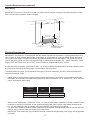
30” 30”
36”
”
”
35”
Note: Range can be raised approximately 1”
(2.5 cm) by adjusting the leveling legs. The
front of door and drawer may extend farther
forward depending on styling.

8
Location Requirements (continued)
Electrical Requirements
Power Supply
IMPORTANT: To connect to an outlet in the wall, the electrical outlet must be recessed. If the electrical outlet is on the
”
30”
”
3”
Recommended location
for electrical outlet
IMPORTANT: This appliance is manufactured with the chassis connected to the neutral by a green ground jumper wire.
Use a 3-wire, UL listed, 50-amp power supply cord (pigtail); or if local codes do not permit ground through the neutral,
use a 4-wire power supply cord rated at 250 volts, 50 amps and intended for use with ranges. The ground must be re-
vised so the green ground wire of the 4-wire power supply is connected to the chassis. See “4-Wire Connection: “Power
Supply Cord” and “Direct Wire - U.S.A. Only” “4-Wire Connection (Ungrounded Neutral)” sections.
the ground path is adequate and wire gauge is in accordance with local codes.
To properly install your range, you must determine the type of electrical connection you will be using and follow the in-
structions provided for it here.
•
4-wire, single-phase power supply.
Frequency Amps Circuit Required
50 A 50 Amp Circuit
43 A 45 Amp Circuit
• When a 4-wire, single phase 120/240-volt, 60 Hz., AC only electrical supply is available, a 50-amp maximum circuit
Hz., AC only electrical supply is available, a 45-amp maximum circuit protection is required).
• For direct wire installations, install a suitable conduit box (not furnished). An appropriately sized UL conduit connector
must be used to correctly attach the conduit to the junction box.
IMPORTANT: Local Codes may vary; installation electrical connections and grounding must comply with all applicable
local codes.

9
Electrical Requirements (continued)
ELECTRICAL REQUIREMENTS - U.S.A. ONLY
• Do not use an extension cord.
• Be sure that the electrical connection and wire size are adequate and in conformance with the National Electrical
Code, ANSI/ NFPA No. 70-latest edition and all local codes and ordinances.
• A copy of the above code standards can be obtained from:
National Fire Protection
Association One Batterymarch Park Quincy, MA 02269.
Electrical Shock Hazard
Do not use an extension cord with this appliance.
Electrical ground is required on this appliance. The free end of the green wire (the ground wire) must be connected to a
suitable ground. This wire must remain grounded to the oven.
If cold water pipe is interrupted by plastic, non metallic gaskets, union connections or other insulating materials, DO
NOT use for grounding.
DO NOT ground to a gas pipe.
DO NOT have a fuse in the NEUTRAL or GROUNDING circuit. A fuse in the NEUTRAL or GROUNDING circuit could
result in an electrical shock.
WARNING
Electrical Shock Hazard
Disconnect power before servicing. Plug into a grounded outlet.
Do not use an extension cord.
WARNING
•
14-50R type SRDT or ST (as required) power cord rated at 250-volt AC minimum, 50 amp, with 3 open-end spade
lug connectors with upturned ends or closed loop connectors and marked for use with ranges.
• A UL listed strain relief must be attached to the range to hold the power cord.
• Do not use an aluminum wire receptacle with copper-wired power cord and plug (or vice versa). The proper wiring and
receptacle are a copper-wired power cord with a copper-wired receptacle.
• The electrical outlet should be located so that the power cord is accessible when the range is in the installed position.
ELECTRICAL REQUIREMENTS - CANADA ONLY
the ground path is adequate and wire gauge are in accordance with local codes.

10
Be sure that the electrical connection and wire size are adequate and in conformance with CSA Standard C22.1, Cana-
dian Electrical Code, Part 1 - latest edition, and all local codes and ordinances.
A copy of the above code standards can be obtained from:
Canadian Standards Association
178 Rexdale Blvd.
Toronto, ON M9W 1R3
CANADA
• Do not use an extension cord.
IMPORTANT: This appliance shall be installed only by authorized persons and in accordance with the
wiring regulations, local water supply regulations.
Electrical Requirements (continued)
Step 2: Imstall Anti-Tip Bracket
Step 1: Unpack Range
Electrical Weight Hazard
Use two or more people to move and install the range. Failure to do so can result in back or other injury.
WARNING
1.
anything until the installation is complete.
2. Remove oven racks and parts package from oven and shipping materials.
3.
range when it is laid on its back.
4.
5. Remove cardboard bottom.
NOTES:
• The leveling legs can be adjusted while the range is on its back.
•
or hardboard.
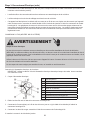
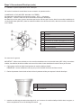
NOTE: An anti-tip bracket kit is provided with the range.
WARNING: Tip Over Hazard
• A child or adult can tip the range and be killed.
• Connect anti-tip bracket to rear range foot.
• Reconnect the anti-tip bracket if the range is moved.
• Failure to follow these instructions can result in death or serious burns to children and adults.

11
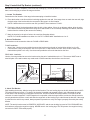
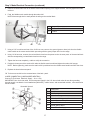
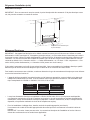
IMPORTANT: DO NOT completely remove the rear leveling leg. The anti-tip bracket uses either the right-hand or left
1: Locate The Bracket
A.
NOTE: If bracket does not touch the rear wall, you MUST screw bracket to FLOOR .
B. Position the side of the bracket against either the left or right cabinet. If there is no adjacent cabinet, align the edge
bracket from the cabinet by the amount of overhang.
C. Mark the location for the pair of holes to be used (see illustration below).
NOTE: For FLOOR installation use either Loc A or B. For REAR WALL installation use Loc C.
2: Secure The Bracket
The bracket must be screwed to either the FLOOR or REAR WALL.
FLOOR Installation:
•
•
REAR WALL Installation:
Use the 2 screws provided to secure the bracket using the pair of marked holes at Loc C. The screws MUST enter a
Step 2: Imstall Anti-Tip Bracket (continued)
Adjacent cabinet
or final location of
range side panel
Attachment to floor or rear wall
Bracket
Wall sill plate
Loc
C
Loc
A
Loc
B
Two screws must
enter floor or wall
at Loc A,B, or C.
Rear Wall
The screw must
enter to wood or
concrete
The screw must enter to wood
3: Check The Bracket
TIP bracket as shown in Step 1. To check if the bracket is installed and engaged properly, look underneath the range
to see that the rear leveling leg is engaged in the bracket. On some models, the storage drawer or kick panel can be
is pulled from the wall for any reason, always repeat this procedure to verify the range is properly secured by the anti-tip
bracket.
NOTE: The anti-tip bracket must be PROPERLY INSTALLED, and the rear leveling leg must be FULLY ENGAGED into
secured to the ANTI-TIP bracket properly.

12
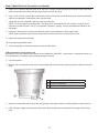
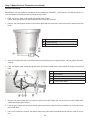
A Access Panel to Electrical Supply Connection
B Power Cord Opening
CRecessed Area
A UL Listed Strain Relief
B Power Cord
C Jumper Wire
Step 3: Make Electrical Connection
POWER CORD - U.S.A. ONLY
Electrical Shock Hazard
Disconnect power before servicing.
Do not use an extension cord.
WARNING
3 Wire connection: power supply cord
IMPORTANT: Use this method only if local codes permit connecting chassis ground conductor to neutral wire of power
supply cord.
1. Disconnect power.
2. Remove the access panel located on the bottom right-hand side of the back panel to uncover the electrical terminal
block
3. Install a UL listed strain relief (not provided) to the power cord opening in the bracket, and then completely tighten the
strain relief nut.
4. Thread the end of the power cord through the strain relief.
NOTE: Allow enough slack to connect the wires to the terminal block.

13
5. Using a 5/16” nut driver and one of the -0-32 hex nuts, connect the neutral (white) wire from the power cord to the
center terminal block post along with the green jumper wire from the range.
6. Using 10-32 hex nuts, connect the red and black wires from the power cord to the outer posts of the terminal block
with the corresponding red and black wires from the range.
7. Tighten the hex nuts completely, and then verify the connection.
NOTE: For power supply cord replacement, use only a power cord rated at 250 volts minimum, 50-amps that is
marked for use with nominal 1 3/8” (3.5 cm) diameter connection opening, with ring terminals and marked for use
with ranges.
8. Position the lower part of the strain relief under the power cord and tighten the strain relief screws.
NOTE: Before tightening, make sure the strain relief is positioned over the cord and NOT the wires.
9. Replace the electrical access panel.
10. Plug range into grounded outlet.
11. Tuck excess power cord into the recessed area of the back panel.
4 Wire connection: power supply cord
IMPORTANT: Use this method for new branch-circuit installations (1996 NEC), mobile homes, recreational vehicles, or
in an area where local codes prohibit grounding through the neutral.
1. Disconnect power.
2. Remove the access panel located on the bottom right-hand side of the back panel to expose the electrical terminal
block.
Step 3: Make Electrical Connection (continued)
A Access Panel to Electrical Supply Connection
B Power Cord Opening
CRecessed Area
3. Install a UL listed strain relief to the power cord opening in the support bracket, and fully tighten the strain relief nut.
4. Feed the power supply cord through the strain relief. Allow enough slack to easily attach the wiring to the terminal
block.

14
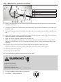
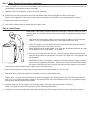
Step 3: Make Electrical Connection (continued)
A Ground Screw
B Terminal Block
C Jumper Wire
D Power Cord Wires
E UL Listed Strain Relief
5. Remove the green jumper wire from under the ground screw and replace with the green wire from the power cord
and tighten ground screw.
6. Loop the green jumper wire removed from the ground screw back onto its end that is fastened to the center post on
the terminal block.
7. Use a 5/16” nut driver to connect the neutral (white) wire to the center terminal block post with one of the 10-32 hex
nuts.
8. Using 10-32 hex nuts, connect the red and black wires from the power cord to the outer posts of the terminal block
with the corresponding red and black wires from the range.
9. Tighten the hex nuts completely, and then verify the connection.
NOTE: For power supply cord replacement, use only a power cord rated at 250 volts minimum, 50-amps that is
marked for use with nominal 1 3/8” (3.5 cm) diameter connection opening, with ring terminals and marked for use
with ranges.
10. Position the lower part of the strain relief under the power cord and tighten the strain relief screws.
NOTE Before tightening, make sure the strain relief is positioned over the cord and NOT the wires.
11. Replace the electrical access panel.
12. Plug range into grounded outlet.
13. Tuck excess power cord into the recessed area of the back panel.
Electrical Shock Hazard
Plug into a grounded outlet.
Do not use an extension cord.
WARNING
1. Plug into a standard 14-50R grounded wall receptacle
2. Go to STEP 4 - INSTALL RANGE 3

15
Step 3: Make Electrical Connection (continued)
Direct Wire U.S.A Only
Electrical Shock Hazard
Disconnect power before servicing.
the home has aluminum wiring, only use connectors designed and UL listed for joining copper to aluminum and pre-
cisely follow the manufacturer’s recommended procedure. Aluminum-to-Copper connections must conform with local
codes.
Use 8-gauge copper or 6-gauge aluminum wire. Electrically ground range.
WARNING
• A circuit breaker is recommended.
•
sheathed, copper or aluminum cable.
• Allow at least 6 ft (1.8 m) of slack in the line so that the range can be moved if servicing is ever necessary.
• A UL listed conduit connector must be provided at each end of the power supply cable (at the range and at the junc-
tion box).
• Wire sizes and connections must conform with the rating of the range.
The tech sheet and wiring diagram are included with the range. This appliance is manufactured with the chassis connect-
-
ble conduit from the oven to the junction box using a UL listed conduit connector. The Grounded Neutral and Ungrounded
Neutral Graphics on the following pages and the instructions provided, present the most common way of connecting the
ovens. Your local codes and ordinances, of course, take precedence over these instructions. Complete electrical connec-
tions according to local codes and ordinances.
3-Wire Connection (Grounded Neutral)
Electrical Shock Hazard
Grounding through the neutral conductor is prohibited for new branch-circuit installations (1996 NEC); mobile homes;
and recreational vehicles, or in an area where local codes prohibit grounding through the neutral conductor. For instal-
lations where grounding through the neutral conductor is prohibited, see the Ungrounded Neutral graphic.
Use grounding terminal or lead to ground unit.
Connect neutral terminal or lead to branch circuit neutral in usual manner.
WARNING

16
Step 3: Make Electrical Connection (continued)
Connect to the House Electrical Supply
IMPORTANT: Use the 3-wire cable from home power supply where local codes permit a 3-wire connection.
1. Disconnect power.
Grounded Neutral
A Junction box
B Black Wires
C Neutral (White) Wire
D Ground (Green or Bare) Wire
E Cable from Range
F UL Listed Conduit Connector
G Red Wires
H UL Listed Wire Connectors
I House Electrical Supply
2. Connect the 2 black wires together using a UL listed wire connector.
3. Connect the neutral (white) wire and the ground (green or bare) wire (of the range cable) using a UL listed wire
connector.
4. Connect the 2 red wires together using a UL listed wire connector.
5. Install junction box cover.
Connect To The Range
IMPORTANT: Use this method only if local codes permit connecting chassis ground conductor to neutral wire of power
supply cord.
1.
NOTE: Allow enough slack to easily attach the wires to the terminal block.
2. Remove the access panel located on the bottom right-hand side of the back panel to uncover the electrical terminal
block.
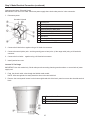
AElectrical Access Panel
B Conduit Opening
CRecessed Area

17
A Junction box
B Black Wires
C Red Wire
D Cable from Range
E UL listed or CSA Approved Conduit Connector
F Ground (Green or Bare) Wires
G UL Listed Wire Connectors
H Neutral (White) Wires
I House Electrical Supply
3.
relief nut.
4.
NOTE:Allow enough slack to easily attach the wiring to the terminal block.
Step 3: Make Electrical Connection (continued)
A Jumper Wire
B UL Listed Strain Relief
C Conduit
5.
metal conduit to the center terminal block post along with the green jumper wire from the range.
6. Using 10-32 hex nuts, connect the red and black wires from the power cord to the outer posts of the terminal block
with the corresponding red and black wires from the range.
7. Tighten the hex nuts completely, and then verify the connection.
8.
9. Replace the electrical access panel.
10. Tuck excess conduit into the recessed area of the back panel.
4-WIRE CONNECTION (UNGROUNDED NEUTRAL)
Connect To The House Electrical Supply - U.s.a. Only
IMPORTANT: Use the 4-wire cable from home power supply in the U.S. where local codes do not allow grounding
through neutral, new branch circuit installations (l99e NEC), mobile homes and recreational vehicles, new construction
and in Canada.
Grounded Neutral

18
Step 3: Make Electrical Connection (continued)
Connect to the Range
IMPORTANT: Use this method for new branch-circuit installations (1996 NEC), mobile homes, recreational vehicles, or
in an area where local codes prohibit grounding through neutral.
1.
NOTE: Allow enough slack to easily attach the wires to the terminal block.
2. Remove the access panel located on the bottom right-hand side of the back panel to expose the electrical terminal
block.
AElectrical Access Panel
B Conduit Opening
CRecessed Area
3.
relief nut.
4.
block.
A Ground Screw
B Terminal Block
C Jumper Wire
D Electrical Cable Wires
E UL Listed Strain Relief
5.
conduit and tighten ground screw.
6. Loop the green jumper wire removed from the ground screw back onto its end that is fastened to the center post on
the terminal block.
7. Use a 5/16” nut driver to connect the neutral (white) wire to the center terminal block post with one of the 10-32 hex
nuts.

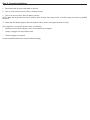
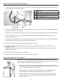
Step 4: Install Range
IMPORTANT: If the range is moved to adjust the leveling legs, make sure when you move
through 9.
1.
Leave a 1” (2.e cm) gap between the back of the range and the back wall.
2. Place the outside of your foot against the bottom front to keep the range from moving,
and then grasp the back of the range, as shown.
3. Slowly attempt to tilt the range forward. If you encounter immediate resistance, the range
foot is engaged in the anti-tip bracket. Go to Step 8.
4.
anti-tip bracket
IMPORTANT: If there is a snapping or popping sound when lifting the range, the range
may not be fully engaged in the bracket. Check to see if there are obstructions keeping
the range from sliding to the wall or keeping the range foot from sliding into the bracket.
5.
6. Slide range back so the rear range foot is inserted into the slot of the anti-tip bracket.
7. Repeat steps 1 through 3 to ensure that the range foot is engaged in the anti-tip bracket.\If the rear of the range lifts more
without anti-tip bracket installed and engaged.
8.
NOTE: The range must be level for optimum cooking and baking performance.
9. If needed, use a wrench to adjust the height of the leveling legs until the range is level from side to side and front to back.
Step 3: Make Electrical Connection (continued)
8. Using 10-32 hex nuts, connect the red and black wires from the power cord to the outer posts of the terminal block with the
corresponding red and black wires from the range.
9. Tighten the hex nuts completely, and then verify the connection.
10.
11. Replace the electrical access panel.
12. Tuck excess conduit into the recessed area of the back panel.

Step 5: Complete Installation
1. Reconnect power to the circuit breaker or fuse box.
2. Turn on each element to check that it is heating correctly.
3. Turn on the oven to check that it is heating correctly.
technician.
4. Check that the indicator lights on the control panel, and the interior oven lights illuminate correctly.
If the range does not operate correctly, check the following:
• Household fuse is intact and tight; or the circuit breaker has not tripped.
• Range is plugged into a grounded outlet.
• Electrical supply is connected.
La page est en cours de chargement...
La page est en cours de chargement...
La page est en cours de chargement...
La page est en cours de chargement...
La page est en cours de chargement...
La page est en cours de chargement...
La page est en cours de chargement...
La page est en cours de chargement...
La page est en cours de chargement...
La page est en cours de chargement...
La page est en cours de chargement...
La page est en cours de chargement...
La page est en cours de chargement...
La page est en cours de chargement...
La page est en cours de chargement...
La page est en cours de chargement...
La page est en cours de chargement...
La page est en cours de chargement...
La page est en cours de chargement...
La page est en cours de chargement...
La page est en cours de chargement...
La page est en cours de chargement...
La page est en cours de chargement...
La page est en cours de chargement...
-
 1
1
-
 2
2
-
 3
3
-
 4
4
-
 5
5
-
 6
6
-
 7
7
-
 8
8
-
 9
9
-
 10
10
-
 11
11
-
 12
12
-
 13
13
-
 14
14
-
 15
15
-
 16
16
-
 17
17
-
 18
18
-
 19
19
-
 20
20
-
 21
21
-
 22
22
-
 23
23
-
 24
24
-
 25
25
-
 26
26
-
 27
27
-
 28
28
-
 29
29
-
 30
30
-
 31
31
-
 32
32
-
 33
33
-
 34
34
-
 35
35
-
 36
36
-
 37
37
-
 38
38
-
 39
39
-
 40
40
-
 41
41
-
 42
42
-
 43
43
-
 44
44


