
celexon Europe GmbH
Gutenbergstraße 2
48282 Emsdetten
NRW, Deutschland
Telefon: +49 2572 92391-2100
Fax: +49 2572 92391-2199
E-Mail: [email protected]
www.celexon.com

BEDIENUNGSANLEITUNG
USER GUIDE

2
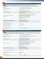
EG-Konformitätserklärung gemäß EG-Richtlinie Maschinen 2006/42/EG, Anhang II A
Hiermit erklären wir, daß die nachstehend bezeichnete Maschine in ihrer Konzeption und Bauart sowie in der von uns in
Verkehr gebrachten Ausführung den grundlegenden Sicherheits- und Gesundheitsanforderungen der EG-Richtlinie
Maschine entspricht. Bei einer mit uns nicht abgestimmten Änderung der Maschine verliert diese Erklärung ihre Gültigkeit.
Hersteller celexon Europe GmbH, 48282 Emsdetten
Bezeichnung der Maschine elektrische Hubsäuleneinheit für Tafelsysteme
Maschinen-Nr. celexon ADJUST (-W, -P, -M, -L, -S)
Zutreff ende EG-Richtlinien
EG-Richtlinie Maschine (2006/42/EG)
EG-Niederspannungsrichtlinie (73/23/EWG)
EG – EMV (2004/108/EG)
Angewandte harmonisierte Normen
insbesondere
EN 14434:2010-04 / EN 60335-1:2012 / EN 62233:2008
EN 61000-4-2:2009 / EN 61000-4-3:2006+A1:2008+A2:2010
EN 61000-4-4:2012 / EN 61000-4-5:2006
EN 61000-4-6:2009 / EN 61000-4-8:2010
EN 61000-4-11:2004 / EN 55024:2010
EN 55022:2010
Angewandte nationale Normen und
technische Spezifi kationen insbesondere
ROHS Directive 2011/65/EU
IEC 61558-1 und 2:2009
C/US Authorisation to Mark „ETL“
PAK ZEK 01.4-08 / EN 14434:2010
Bevollmächtigter für die
Zusammenstellung der Dokumente Jens Gehring
Name des Unterzeichners Christoph Hertz
Funktion des Unterzeichners CEO
Datum/Unterschrift 12.11.2015,
EC-Declaration of Conformity in accordance with European directive 2006/42/EG, part II A
We hereby certify that the machine described hereafter, in its design and construction and in the model put into circulation, com-
plies with all relevant health and safety requirements of the EC machinery directive 2006/42/EG. Any modifi cation to our product,
without our written consent, will result in this declaration to become void.
Manufactors name celexon Europe GmbH, 48282 Emsdetten
Description of the machine motorized lift system for displays and (interactive) boards
Part-No. celexon ADJUST (-W, -P, -M, -L, -S)
European directive(s)
EC-machinery directive (2006/42/EG)
EC-low voltage directive (73/23/EEC)
EMC directive (2004/108/EG)
European standards
EN 14434:2010-04 / EN 60335-1:2012 / EN 62233:2008
EN 61000-4-2:2009 / EN 61000-4-3:2006+A1:2008+A2:2010
EN 61000-4-4:2012 / EN 61000-4-5:2006
EN 61000-4-6:2009 / EN 61000-4-8:2010
EN 61000-4-11:2004 / EN 55024:2010
EN 55022:2010
National standards and specifi cations
ROHS Directive 2011/65/EU
IEC 61558-1 and 2:2009
C/US authorisation to mark „ETL“
PAK ZEK 01.4-08 / EN 14434:2010
Person in charge for document collection Jens Gehring
Declaration signed by Christoph Hertz
Position CEO
Date and signature 12.11.2015,
EG-Konformitätserklärung
Hiermit erklären wir, daß die nachstehend bezeichnete Maschine in ihrer Konzeption und Bauart sowie in der von uns in
Verkehr gebrachten Ausführung den grundlegenden Sicherheits- und Gesundheitsanforderungen der EG-Richtlinie
EC-Declaration of Conformity
We hereby certify that the machine described hereafter, in its design and construction and in the model put into circulation, com-
plies with all relevant health and safety requirements of the EC machinery directive 2006/42/EG. Any modifi cation to our product,

3
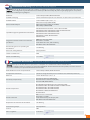
EU conformiteitsverklaring volgens EG-richtlijn 2006/42/EG, bijlage II A
Hierbij verklaren wij,dat de hierna beschreven producten, in ontwerp en constructie alsmede in de in omloop gebrachte uitvoering,
voldoen aan de veiligheids-en gezondheidseisen van de Europese Machinerichtlijn. Bij onbevoegde wijzigingen aan ons product
verliest deze verklaring haar geldigheid.
Producent celexon Europe GmbH, 48282 Emsdetten
Produktbeschrijving electrisch kolommensysteem voor monitoren en (interactieve) schoolborden
Produktnummer celexon ADJUST (-W, -P, -M, -L, -S)
Geldende EG richtlijnen
EG-machinerichtlijn (2006/42/EG)
EG-laagspanningsrichtlijn (73/23/EWG)
EMC richtlijn (2004/108/EG)
Specifi ek toegepaste geharmoniseerde normen
EN 14434:2010-04 / EN 60335-1:2012 / EN 62233:2008
EN 61000-4-2:2009 / EN 61000-4-3:2006+A1:2008+A2:2010
EN 61000-4-4:2012 / EN 61000-4-5:2006
EN 61000-4-6:2009 / EN 61000-4-8:2010
EN 61000-4-11:2004 / EN 55024:2010
EN 55022:2010
Toegepaste nationale normen en technische
specifi caties
ROHS Directive 2011/65/EU
IEC 61558-1 en 2:2009
C/US authorisatie voor „ETL“ markering
PAK ZEK 01.4-08 / EN 14434:2010
Gevolmachtigde voor de opstelling der
documenten Jens Gehring
Naam van ondergetekende Christoph Hertz
Funktie ondertekenaar CEO
Datum / Handtekening 12.11.2015,
EC-Declaration de Conformité Conformément à la directive européenne 2006/42/CE, partie II A
Nous certifi ons que la machine décrite ci-après, dans sa conception et sa construction et dans le modèle mis en
circulation, conforme à toutes les exigences de la directive 2006/42/CE. Toute modifi cation de notre produit, sans notre consente-
ment écrit, se traduira par la présente déclaration à devenir nulle.
Nom du fabricant ou de son représentant celexon Europe GmbH, 48282 Emsdetten
Description de la machine système de levage motorisé pour les moniteurs et les tableaux (interactive)
Réference celexon ADJUST (-W, -P, -M, -L, -S)
Directive(s) européenne(s)
Directive CE machines (2006/42/CE)
Directive CE basse tension (73/23/CEE)
Directive CEM (2004/108/CE)
Normes européennes
EN 14434:2010-04 / EN 60335-1:2012 / EN 62233:2008
EN 61000-4-2:2009 / EN 61000-4-3:2006+A1:2008+A2:2010
EN 61000-4-4:2012 / EN 61000-4-5:2006
EN 61000-4-6:2009 / EN 61000-4-8:2010
EN 61000-4-11:2004 / EN 55024:2010
EN 55022:2010
Normes nationales
ROHS Directive 2011/65/EU
IEC 61558-1 et 2:2009
C/US authorisation pour marquer „ETL“
PAK ZEK 01.4-08 / EN 14434:2010
Responsable de collection de documents Jens Gehring
Déclaration signée par Christoph Hertz
Position CEO
Date et signature 12.11.2015,
EU conformiteitsverklaring
Hierbij verklaren wij,dat de hierna beschreven producten, in ontwerp en constructie alsmede in de in omloop gebrachte uitvoering,
voldoen aan de veiligheids-en gezondheidseisen van de Europese Machinerichtlijn. Bij onbevoegde wijzigingen aan ons product
EC-Declaration de Conformité
Nous certifi ons que la machine décrite ci-après, dans sa conception et sa construction et dans le modèle mis en
circulation, conforme à toutes les exigences de la directive 2006/42/CE. Toute modifi cation de notre produit, sans notre consente-

4
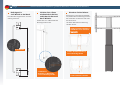
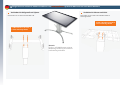
Montage wandmontiertes elektrisch höhenverstellbares System für Monitore und interaktive Monitore
Montage wandmontiertes elektrisch höhenverstellbares System für Monitore und interaktive Monitore
Befestigen Sie
2 x Z-Winkel an der Wand.
Kein Wandmontagematerial im Liefer-
umfang enthalten.
Schieben Sie 2 x Platte
mit Gewinde in die Nut,
verbinden Sie diese mit
den Z-Winkeln.
Verwenden Sie 2 x Mutter M8 und
Unterlegscheibe 8 mm.
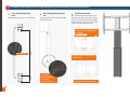
Montieren Sie den Rahmen.
Verwenden Sie 4 x Inbusschraube M8
x 75, Mutter M8 und Unterlegscheibe 8
mm. Verbinden Sie Rahmen und Säule
mit den 4 Inbus-
schrauben M8 x 40 und 2 Unterleg-
scheiben hinten.
2 x Platte mit
Gewinde, 2 x Mutter M8,
2 x 8 mm Unterlegscheibe.
2 x Z-Winkel
≈ 10 cm ≈ 55 cm
4 x M8 x 75 Inbusschraube, 4
x M8 Mutter, 8 x 8 mm Unter-
legscheibe
legscheibe
2 x M8 x 40 Inbusschraube
2 x M8 x 40 Inbusschraube, 2
x 8 mm Unterlegscheibe

5
4 x allen head screw M8 x 75,
4 x nut M8,
8 x washer 8 mm
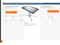
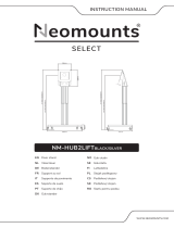
Assembly wallmounted electrical height adjustable system for displays and interactive displays
Fix 2 x Z-bracket to the
wall.
Wallmounting material is not included.
Put 2 sliding blocks into the
rail
.
Fix it to the Z-bracket using 2 x nut M8
and washer 8 mm.
Assemble the frame.
Use 4 x allen head screw M8 x 75, nut
M8, washer 8 mm. Fix the frame to the
column. Use 2 x allen head screw M8 x
40 and washer in the back and 2 x allen
head screw M8 x 40 in the front.
2 x sliding
block with thread,
2 x nut M8,
2 x washer 8 mm
2 x Z-bracket
≈ 10 cm ≈ 55 cm
8 x washer 8 mm
2 x allen head screw M8 x 40, 2 x
washer 8 mm
2 x allen head screw M8 x 40

6
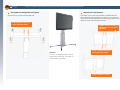
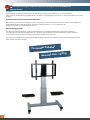
Montage fahrbares elektrisch höhenverstellbares System für Monitore und interaktive Monitore
Montage fahrbares elektrisch höhenverstellbares System für Monitore und interaktive Monitore
Verbinden Sie Rollgestell und Pylone.
Verwenden Sie 4 x Inbusschraube M8 x 40.
Montieren Sie den Rahmen.
Verwenden Sie 4 x Inbusschraube M8 x 75, Mutter M8 und
Unterlegscheibe 8 mm. Verbinden Sie Rahmen und Säule mit
den 2 Inbusschrauben M8 x 40 und 2 Unterlegscheiben hinten
und den 2 Inbusschrauben M8 x 40 vorne.
4 x M8 x 75 Inbusschraube, 4
x M8 Mutter, 8 x 8 mm Unter-
legscheibe
4 x M8 x 40 Inbusschraube, 4
x 8 mm Unterlegscheibe
legscheibe
2 x M8 x 40 Inbusschraube, 2
x 8 mm Unterlegscheibe
2 x M8 x 40 Inbusschraube
Hinweis:
Displays auf Abbildungen in dieser
Bedienungsanleitung sind nicht im
Lieferumfang enthalten.

7
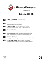
Assembly mobile electrical height adjustable system for displays and interactive displays
Connect the trolley to the column.
Use 4 x allen head screw M8 x 40.
Assemble the frame.
Use 4 x allen head screw M8 x 75, nut M8, washer
8 mm. Fix the frame to the column. Use 2 x allen head screw
M8 x 40 and washer in the back and 2 x allen head screw M8 x
40 in the front.
4 x allen head screw M8 x 40,
4 x washer 8 mm 4 x allen head screw M8 x 75,
4 x nut M8,
8 x washer 8 mm
2 x allen head screw M8 x 40, 2 x
washer 8 mm
2 x allen head screw M8 x 40
Hinweis:
Displays auf Abbildungen in dieser
Bedienungsanleitung sind nicht im
Lieferumfang enthalten.

8
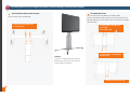
Montage fahrbares elektrisch höhenverstellbares und schrägstellbares System für Monitore und interaktive Monitore
Montage fahrbares elektrisch höhenverstellbares und schrägstellbares System für Monitore und interaktive Monitore
Verbinden Sie Rollgestell und Pylone.
Verwenden Sie 4 x Inbusschraube M8 x 40.
4 x M8 x 40 Inbusschraube, 4
x 8 mm Unterlegscheibe
Verbinden Sie Rahmen und Säule.
Verwenden Sie 4 x Inbusschraube M8 x 40 und
Unterlegscheibe.
4 x M8 x 40 Inbusschraube, 4
x 8 mm Unterlegscheibe
Hinweis:
Displays auf Abbildungen in dieser
Bedienungsanleitung sind nicht im
Lieferumfang enthalten.

9
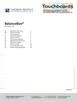
Assembly mobile electrical height adjustable and tiltable system for displays and interactive displays
Connect the trolley to the column.
Use 4 x allen head screw M8 x 40.
Fix the frame to the column.
Use 4 x allen head screw M8 x 40 and washer.
4 x allen head screw M8 x 40, 4 x
washer 8 mm
4 x allen head screw M8 x 40,
4 x washer 8 mm
Hinweis:
Displays auf Abbildungen in dieser
Bedienungsanleitung sind nicht im
Lieferumfang enthalten.

10
Bedienungsanleitung für elektrische Höhenverstellungseinheit der Modellreihe
celexon ADJUST
Recht herzlichen Dank für den Erwerb unseres Höhenverstellungssystems. Bitte lesen Sie die beiliegenden
Unterlagen vor der Benutzung sorgfältig durch. Der Aufbau ist unkompliziert, sollte aber nur durch geschultes Fachpersonal
erfolgen.
Grundsätzliche Hinweise zur Inbetriebnahme
Bitte prüfen Sie vor Anschluss der Einheit an das Stromnetz, dass keinerlei Hindernisse (Tische, Stühle, andere Möbel oder
Raumanbauteile) die freie Beweglichkeit der Einheit behindern können. Lesen Sie dazu auch die
beiliegenden Gefahren- und Sicherheitshinweise.
Verwendungsgrenzen
Die Höhenverstellungseinheit ist lediglich zum Anbau unserer geprüften Komponenten (Fahrgestell, Montage-
vorrichtungen für interaktive Komponenten, etc.) gedacht. Bitte verwenden Sie keine Anbauteile anderer Hersteller,
da wir für diese keine Garantie für Funktion und Sicherheit übernehmen können.
Die maximale Gesamtbelastung der Säule beträgt 150 kg. Das Gewicht der angebauten interaktiven Komponenten darf
daher 120 kg nicht überschreiten.
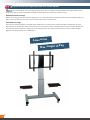
Bedienungsanleitung für elektrische Höhenverstellungseinheit der Modellreihe
celexon ADJUST
Passendes Zubehör
Gewicht max. 150 kg

11
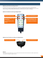
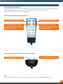
Bedienung der Höhenverstellungseinheit
Die Höhenverstellung der Säule erfolgt, indem Sie die Tasten an der Bedieneinheit drücken und gedrückt halten.
Beim Loslassen der Einheit stoppt die Bewegung sofort. Im Gefahrenfall daher lediglich die Bedieneinheit loslassen (Tot-
mannschaltung). Für weitere Informationen steht Ihnen Ihr Fachhandelspartner gerne zur Verfügung.
Bedieneinheit Höhenverstellung mit Kippfunktion
Bedieneinheit für Höhenverstellung ohne Kippfunktion
Hinweis
Änderungen an den Komponenten, die der Sicherheit oder dem technischen Fortschritt dienen, können jederzeit ohne
vorherige Ankündigung durchgeführt werden.
Hebt die Hubeinheit an Senkt die Hubeinheit ab
Kippt den Rahmen in die
Horizontale
(nur bei kippbaren Ein-
heiten)
Hebt den Rahmen in die
senkrechte Position (nur
bei kippbaren Einheiten)
Senkt die Hubeinheit abHebt die Hubeinheit an

12
User guide for electrical height adjustable units celexon ADJUST
Thank you for purchasing our electrical height ajustable units. Please carefully read all provided informations before assem-
bling and usage. Assembly is uncomplicated but should be done by trained service personal only.
General hints for startup
Before connecting the unit to the power supply please check that up/down movement of the unit will not be blocked by any
table, chair, other furniture etc. Please also read attached hazard and safety notes.
Limitation of usage
This unit must not be equipped / used with other components (I.e. trolley, frame unit for interaktive components, etc.
) but
those, which are certifi ed by us. We cannot take over any warranty for safety and proper function for third party components.
The maximum load of the unit is 150 kg. So do not mount external units (Interactive monitors, boards etc) with a weight
higher than 120 kg or others not certifi ed by us.
User guide for electrical height adjustable units celexon ADJUST
Thank you for purchasing our electrical height ajustable units. Please carefully read all provided informations before assem-
Thank you for purchasing our electrical height ajustable units. Please carefully read all provided informations before assem-
Accessories
Max. weight 150 kg

13
Usage of hight adjustable unit
For moving the unit up or down just press and keep pressed the buttons on the control unit. Releasing the button will imme-
diately stop the movement. So in case of emergency just unhand the control unit (watch dog switch).
For further information your dealer will be at your disposal.
Control unit for tiltable hight adjustable unit
Control unit for hight adjustable unit without tilt function
Hint
Changes made to components, which serve to technical progress, can be put into aff ect without prior notice.
Pressing knob lowers lift unitPressing knob raises lift unit
Pressing knob moves frame
unit to the horizontal position
(tiltable units only)
Pressing knob moves frame
unit to the horizontal position
(tiltable units only)
Pressing knob lowers lift unit
Pressing knob raises lift unit

14
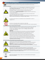
Gefahren- und Sicherheitshinweise
Lesen Sie die nachfolgenden Gefahren- & Sicherheitshinweise vor der Verwendung der Höhenverstellungs
einheit
sorgfältig durch. Dies trägt dazu bei, daß die Einheit störungsfrei arbeitet & Unfälle vermieden werden.
Elektrische Sicherheit
Anschluss der Einheit nur an eine frei zugängliche schutzgeerdete Steckdose mit
110 – 230 Volt / 50 Hz, damit das Gerät im Notfall direkt, ohne Verzögerung vom
Stromnetz getrennt werden kann.
Betrieb der Einheit nur in trockenen Räumen erlaubt, vor Wasser & anderen
Flüssigkeiten schützen. System zur Reinigung nur trocken abwischen.
Gerät nicht öff nen. STROMSCHLAGGEFAHR. Es befi nden sich keine wartbaren Teile
im Inneren der Hubsäule.
Im Störungsfall die Hubeinheit vom Stromnetz trennen und einen authorisierten
technischen Kundendienst benachrichtigen.
Netzkabel nicht überfahren oder auf andere Art beschädigen. Beschädigte Netzkabel nicht
mehr verwenden und sofort durch neue gleichen Typs ersetzen.
Die elektrischen Anschlüsse an der Hubsäule und an der Wand müssen stets frei
zugänglich sein.
Das Gerät ist nicht gegen Tropf- und Spritzwasser geschützt.
Keine mit Flüssigkeit gefüllten Gegenstände darauf abstellen oder das Gerät besprühen.
Allgemeine Hinweise zur mechanischen Sicherheit
Höhenverstellungseinheit nicht unsachgemäss belasten. Keine Teile ausser den dafür
bestimmten und geeigneten Teilen verwenden (Projektionsfl äche, Tafelfl ügel,
Interaktives Board, Monitor, Projektor). Nicht an Tafelfl ügel, Mittelfl äche oder
Projektorhalterung hängen.
ACHTUNG:
Hohes Gewicht. Durch Umfallen der Einheit besteht ernsthafte Verletzungsgefahr.
Nur mitgeliefertes Original-Befestigungsmaterial und Originalteile verwenden.
Die maximale Belastung der Hubeinheit von 150 kg nicht überschreiten.
Aufbau und Anschluss des Systems nur durch den authorisierten Fachhandel.
Beim Hoch- & Herunterfahren der Höhenverstellung mindestens einen Abstand
von 20 cm zu allen am System anmontierten Teilen einhalten um Quetsch- & Scher-
stellen zu vermeiden. Stellen Sie die Einsehbarkeit des Arbeitsbereiches sicher.
Im Gefahrenfall sofort die Bedieneinheit loslassen. Die Bewegung der Hubsäule
stoppt sofort (Totmannschaltung).
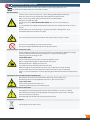
Besondere Hinweise für fahrbare und freistehende Systeme
Die Einheit nur auf ebenen & standsicheren Untergründen betreiben.
Fahrbare Systeme nur auf ebenen Untergründen bewegen. Es besteht insbesondere
Kippgefahr beim Überfahren von Bodenunebenheiten, Türschwellen o.ä. hohes
Gewicht. Durch Umfallen der Einheit besteht ernsthafte Verletzungsgefahr.
Bei Benutzung von fahrbaren Einheiten vor Benutzung der Einheit Feststellbremsen betätigen.
Besondere Hinweise für wandmontierte Systeme
Nur geeignetes Wandbefestigungsmaterial verwenden. Je nach bauseitigen
Gegebenheiten und Eigenschaften der Wand müssen geeignete Dübel und Schrauben
verwendet werden. Bei der Verwendung von ungeeignetem Befestigungsmaterial
besteht ernsthafte Verletzungsgefahr durch Umkippen der Einheit. Wandmontage nur durch
ausgebildetes Fachpersonal ausführen lassen.
Entsorgungshinweis
Gerät nicht im Hausmüll entsorgen sondern einer speziellen Wiederverwertung für
Elektroschrott zuführen.
Gefahren- und Sicherheitshinweise
Lesen Sie die nachfolgenden Gefahren- & Sicherheitshinweise vor der Verwendung der Höhenverstellungs
sorgfältig durch. Dies trägt dazu bei, daß die Einheit störungsfrei arbeitet & Unfälle vermieden werden.
Lesen Sie die nachfolgenden Gefahren- & Sicherheitshinweise vor der Verwendung der Höhenverstellungs

15
Important hazard and safety notes
Please carefully read the below hazard and safety notes before using the hight adjustment unit.
This adds to make the unit works failure free and avoids accidents.
Electrical safety
Connect unit to a free accessible 110 – 230 V / 50 Hz grounded power outlet only.
Make sure, the unit can be immediately separated from the power outlet.
Only use unit in dry rooms, protect unit from water and other liquids.
Only wipe unit with dry cloth.
Do not open lift unit. RISK OF ELECTRIC SHOCK. There are no serviceable parts
inside.
In case of disfunction unplug unit from power outlet and call a authorised technical service
person.
Do not overrun line cord or damage in any other way. Replace damaged line cords
immediately with new one from same type.
The socket connections of the unit and the wall socket must be easily accessible.
The device is not dripping or splash water protected.
Do not place objects fi lled with liquids on or spray the device.
General hints for mechanical safety
Do not improperly weight unit. Do not mount other than original parts (whiteboard, wings,
interactive board, interactive monitor, projector) in conjunction with original
mounting parts. Do not hang on unit.
! VERY HEAVY UNIT.
Severe risk of injury when unit falls over due to improper usage.
Only use original mounting parts provided with the system.
Max load of lift unit is 150 kg. Do not exceed.
Installation of unit by authorized service person only.
Before moving the unit up or down ashure at least a safety distance of 20 cm from
any part of the unit to any other fi tment in order to avoid shear traps or squeezing
points. In case of accident please release operating panel. Movement of unit will stop immedi-
ately.
Special hints for moveable und free standing units
Only operate unit on plane and stable fl oors. Move unit on plane fl oors only.
Risk of tilting when overrunning fl oorunevennesses, door sills and similar.
! VERY HEAVY UNIT.
Severe risk of injury when unit falls over.
Lock brakes of front wheels when operating unit.
Special hints for wall mounted units
Use appropriate wall mounting material only. Choose douwels and screws according
to the wall type and material. Using improper mounting material may result in tilting of
the unit and severe risk of injury.
Wall mounting must be done by experienced personal only.
Instructions for disposal
Do not dispose to consumer waste.
Important hazard and safety notes
Please carefully read the below hazard and safety notes before using the hight adjustment unit.
This adds to make the unit works failure free and avoids accidents.
Please carefully read the below hazard and safety notes before using the hight adjustment unit.
-
 1
1
-
 2
2
-
 3
3
-
 4
4
-
 5
5
-
 6
6
-
 7
7
-
 8
8
-
 9
9
-
 10
10
-
 11
11
-
 12
12
-
 13
13
-
 14
14
-
 15
15
-
 16
16


Celexon Professional Plus stojak pod wyświetlacz Fixed-42100P Le manuel du propriétaire
- Taper
- Le manuel du propriétaire
- Ce manuel convient également à
dans d''autres langues
Documents connexes
-
Celexon tafelprojectiescherm Mobil Professional 81 x 61cm Le manuel du propriétaire
-
-
-
-
-
-
-
Autres documents
-
 CONEN MST-SCETA-V Guide d'installation
-
 CONEN SCETTA Assembly Guide
-
 CONEN SCETTA Assembly Instructions
-
 CONEN SCETAVBOX Assembly Instructions
-
 CONEN CCET50-WBL Assembly Guide
-
 Neomounts PLASMA-M2250BLACK Manuel utilisateur
-
 Neomounts NM-HUB2LIFT Manuel utilisateur
-
Mode CINTIQ 21UX Manuel utilisateur
-
 Tonino Lamborghini El.Rasenm Le manuel du propriétaire
-
 BALD 480A02 Guide d'installation


