Dell PowerConnect B-TI24x Guide de démarrage rapide
- Taper
- Guide de démarrage rapide

53-1002265-01
18 March 2011
Dell PowerConnect B-
Series TI24X
Hardware Installation Guide

Information in this document is subject to change without notice.
© 2011 Dell Inc. All rights reserved.
Reproduction of these materials in any manner whatsoever without the written permission of Dell Inc. is strictly forbidden.
Trademarks used in this text: Dell, the DELL logo,, Dell OpenManage and PowerConnect are trademarks of Dell Inc.; Microsoft,
Windows, Windows Server, MS-DOS and Windows Vista are either trademarks or registered trademarks of Microsoft Corporation
in the United States and/or other countries.
Other trademarks and trade names may be used in this document to refer to either the entities claiming the marks and names or
their products. Dell Inc. disclaims any proprietary interest in trademarks and trade names other than its own.
Regulatory Model Codes: TurboIron 24X

Dell PowerConnect B-Series TI24X Hardware Installation Guide iii
53-1002265-01
Contents
About This Document
In this chapter . . . . . . . . . . . . . . . . . . . . . . . . . . . . . . . . . . . . . . . . . . . vii
Audience . . . . . . . . . . . . . . . . . . . . . . . . . . . . . . . . . . . . . . . . . . . . . . . vii
Supported hardware and software . . . . . . . . . . . . . . . . . . . . . . . . . . vii
Document conventions. . . . . . . . . . . . . . . . . . . . . . . . . . . . . . . . . . . . vii
Text formatting . . . . . . . . . . . . . . . . . . . . . . . . . . . . . . . . . . . . . . . viii
Command syntax conventions . . . . . . . . . . . . . . . . . . . . . . . . . . viii
Notes, cautions, and danger notices . . . . . . . . . . . . . . . . . . . . . viii
Related publications . . . . . . . . . . . . . . . . . . . . . . . . . . . . . . . . . . . . . . . ix
Getting technical help or reporting errors . . . . . . . . . . . . . . . . . . . . . . ix
Contacting Dell . . . . . . . . . . . . . . . . . . . . . . . . . . . . . . . . . . . . . . . . . . . ix
Chapter 1 Product Overview
In this chapter . . . . . . . . . . . . . . . . . . . . . . . . . . . . . . . . . . . . . . . . . . . . 1
Product overview. . . . . . . . . . . . . . . . . . . . . . . . . . . . . . . . . . . . . . . . . . 1
Software features . . . . . . . . . . . . . . . . . . . . . . . . . . . . . . . . . . . . . . . . . 1
Hardware features . . . . . . . . . . . . . . . . . . . . . . . . . . . . . . . . . . . . . . . . 1
Control features . . . . . . . . . . . . . . . . . . . . . . . . . . . . . . . . . . . . . . . 2
Network interfaces. . . . . . . . . . . . . . . . . . . . . . . . . . . . . . . . . . . . . 3
LEDs for network interfaces and power supplies . . . . . . . . . . . . 5
Power supplies . . . . . . . . . . . . . . . . . . . . . . . . . . . . . . . . . . . . . . . . 6
Chapter 2 Installing the PowerConnect B-Series TI24X
In this chapter . . . . . . . . . . . . . . . . . . . . . . . . . . . . . . . . . . . . . . . . . . . . 9
Unpacking a system . . . . . . . . . . . . . . . . . . . . . . . . . . . . . . . . . . . . . . . 9
Package contents . . . . . . . . . . . . . . . . . . . . . . . . . . . . . . . . . . . . . 9
General requirements . . . . . . . . . . . . . . . . . . . . . . . . . . . . . . . . . 10
Summary of installation tasks . . . . . . . . . . . . . . . . . . . . . . . . . . . . . . 10
Installation precautions . . . . . . . . . . . . . . . . . . . . . . . . . . . . . . . . . . . 11
General precautions . . . . . . . . . . . . . . . . . . . . . . . . . . . . . . . . . .11
Lifting precautions. . . . . . . . . . . . . . . . . . . . . . . . . . . . . . . . . . . .12
Power precautions . . . . . . . . . . . . . . . . . . . . . . . . . . . . . . . . . . . .12
Preparing the installation site . . . . . . . . . . . . . . . . . . . . . . . . . . . . . .15
Cabling infrastructure . . . . . . . . . . . . . . . . . . . . . . . . . . . . . . . . .15
Installation location . . . . . . . . . . . . . . . . . . . . . . . . . . . . . . . . . . .15

iv Dell PowerConnect B-Series TI24X Hardware Installation Guide
53-1002265-01
Installing the device . . . . . . . . . . . . . . . . . . . . . . . . . . . . . . . . . . . . . .15
Desktop installation. . . . . . . . . . . . . . . . . . . . . . . . . . . . . . . . . . .15
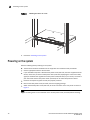
Rack mount installation . . . . . . . . . . . . . . . . . . . . . . . . . . . . . . .15
Powering on the system . . . . . . . . . . . . . . . . . . . . . . . . . . . . . . . . . . .18
Powering off the system . . . . . . . . . . . . . . . . . . . . . . . . . . . . . . . 19
Verifying proper operation . . . . . . . . . . . . . . . . . . . . . . . . . . . . . . . . .19
Observing the power status LEDs. . . . . . . . . . . . . . . . . . . . . . . .20
Attaching a PC or terminal . . . . . . . . . . . . . . . . . . . . . . . . . . . . . . . . .20
Chapter 3 Connecting Network Devices and Checking Connectivity
In this chapter . . . . . . . . . . . . . . . . . . . . . . . . . . . . . . . . . . . . . . . . . . . 23
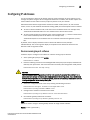
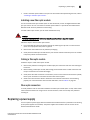
Assigning permanent passwords . . . . . . . . . . . . . . . . . . . . . . . . . . . .23
Recovering from a lost password . . . . . . . . . . . . . . . . . . . . . . . . 24
Configuring IP addresses . . . . . . . . . . . . . . . . . . . . . . . . . . . . . . . . . .25
Devices running Layer 2 software . . . . . . . . . . . . . . . . . . . . . . .25
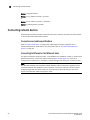
Connecting network devices. . . . . . . . . . . . . . . . . . . . . . . . . . . . . . . .26
Connectors and cable specifications . . . . . . . . . . . . . . . . . . . . .26
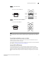
Connecting to Ethernet or fast Ethernet hubs . . . . . . . . . . . . . .26
Connecting to workstations, servers, or routers . . . . . . . . . . . . 27
Connecting a network device to a fiber port . . . . . . . . . . . . . . .28
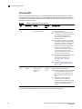
Testing connectivity. . . . . . . . . . . . . . . . . . . . . . . . . . . . . . . . . . . . . . .29
Pinging an IP address . . . . . . . . . . . . . . . . . . . . . . . . . . . . . . . . .29
Observing LEDs . . . . . . . . . . . . . . . . . . . . . . . . . . . . . . . . . . . . . .30
Tracing a route . . . . . . . . . . . . . . . . . . . . . . . . . . . . . . . . . . . . . . . 31
Troubleshooting network connections. . . . . . . . . . . . . . . . . . . . . . . . 31
Support for digital optical monitoring. . . . . . . . . . . . . . . . . . . . . 31
Chapter 4 Managing the PowerConnect B-Series TI24X
In this chapter . . . . . . . . . . . . . . . . . . . . . . . . . . . . . . . . . . . . . . . . . . . 33
Managing temperature settings. . . . . . . . . . . . . . . . . . . . . . . . . . . . .33
Using the temperature sensor . . . . . . . . . . . . . . . . . . . . . . . . . .33
Displaying the temperature. . . . . . . . . . . . . . . . . . . . . . . . . . . . .33
Displaying temperature messages . . . . . . . . . . . . . . . . . . . . . . .34
Changing the temperature warning level . . . . . . . . . . . . . . . . . .34
Changing the device temperature polling interval. . . . . . . . . . .34
Removing MAC address entries . . . . . . . . . . . . . . . . . . . . . . . . . . . . .35
Chapter 5 Maintaining the PowerConnect B-Series TI24X Hardware
In this chapter . . . . . . . . . . . . . . . . . . . . . . . . . . . . . . . . . . . . . . . . . . . 37
Hardware maintenance schedule . . . . . . . . . . . . . . . . . . . . . . . . . . . 37

Dell PowerConnect B-Series TI24X Hardware Installation Guide v
53-1002265-01
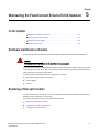
Replacing a fiber optic module . . . . . . . . . . . . . . . . . . . . . . . . . . . . . 37
Removing a fiber optic module . . . . . . . . . . . . . . . . . . . . . . . . . .38
Installing a new fiber optic module. . . . . . . . . . . . . . . . . . . . . . .39
Cabling a fiber optic module . . . . . . . . . . . . . . . . . . . . . . . . . . . .39
Fiber-optic connectors . . . . . . . . . . . . . . . . . . . . . . . . . . . . . . . . .39
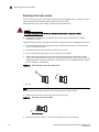
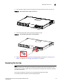
Replacing a power supply. . . . . . . . . . . . . . . . . . . . . . . . . . . . . . . . . .39
Installation precautions and warnings . . . . . . . . . . . . . . . . . . . .40
Determining which power supply failed . . . . . . . . . . . . . . . . . . .40
AC power supplies . . . . . . . . . . . . . . . . . . . . . . . . . . . . . . . . . . . . 41
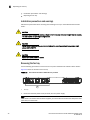
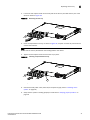
Replacing the fan tray. . . . . . . . . . . . . . . . . . . . . . . . . . . . . . . . . . . . .45
Installation precautions and warnings . . . . . . . . . . . . . . . . . . . .46
Removing the fan tray . . . . . . . . . . . . . . . . . . . . . . . . . . . . . . . . .46
Appendix A Hardware Specifications
Device specifications . . . . . . . . . . . . . . . . . . . . . . . . . . . . . . . . . . . . .50
Physical dimensions and weight. . . . . . . . . . . . . . . . . . . . . . . . .50
Environmental considerations . . . . . . . . . . . . . . . . . . . . . . . . . .50
Cooling . . . . . . . . . . . . . . . . . . . . . . . . . . . . . . . . . . . . . . . . . . . . .50
Regulatory compliance . . . . . . . . . . . . . . . . . . . . . . . . . . . . . . . . 51
Power source interruptions . . . . . . . . . . . . . . . . . . . . . . . . . . . . .52
Mean Time between Failure . . . . . . . . . . . . . . . . . . . . . . . . . . . . 52
Pinouts and signalling . . . . . . . . . . . . . . . . . . . . . . . . . . . . . . . . .52
Cable specifications. . . . . . . . . . . . . . . . . . . . . . . . . . . . . . . . . . .53
PDU power cords(C13-C14). . . . . . . . . . . . . . . . . . . . . . . . . . . . . 55
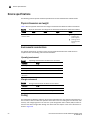
Power supply specifications . . . . . . . . . . . . . . . . . . . . . . . . . . . . . . . .55
Overview . . . . . . . . . . . . . . . . . . . . . . . . . . . . . . . . . . . . . . . . . . . .55
Key features . . . . . . . . . . . . . . . . . . . . . . . . . . . . . . . . . . . . . . . . .55
Physical dimensions and weight. . . . . . . . . . . . . . . . . . . . . . . . .56
Environmental considerations . . . . . . . . . . . . . . . . . . . . . . . . . .56
Power supply consumption . . . . . . . . . . . . . . . . . . . . . . . . . . . . . 57
Input connector and plug . . . . . . . . . . . . . . . . . . . . . . . . . . . . . . 57
Regulatory compliance . . . . . . . . . . . . . . . . . . . . . . . . . . . . . . . .58
Safety warnings . . . . . . . . . . . . . . . . . . . . . . . . . . . . . . . . . . . . . .58
Electrical specifications. . . . . . . . . . . . . . . . . . . . . . . . . . . . . . . .59
Appendix B Regulatory Approval and Statements
Agency approvals . . . . . . . . . . . . . . . . . . . . . . . . . . . . . . . . . . . . . . . . 61
Safety agency approvals . . . . . . . . . . . . . . . . . . . . . . . . . . . . . . . 61
Electromagnetic emission . . . . . . . . . . . . . . . . . . . . . . . . . . . . . . 61
Immunity. . . . . . . . . . . . . . . . . . . . . . . . . . . . . . . . . . . . . . . . . . . . 61
Regulatory statements . . . . . . . . . . . . . . . . . . . . . . . . . . . . . . . . . . . .62
U.S.A.. . . . . . . . . . . . . . . . . . . . . . . . . . . . . . . . . . . . . . . . . . . . . . .62
Industry Canada statement. . . . . . . . . . . . . . . . . . . . . . . . . . . . .62
Europe and Australia . . . . . . . . . . . . . . . . . . . . . . . . . . . . . . . . . .62
Japan . . . . . . . . . . . . . . . . . . . . . . . . . . . . . . . . . . . . . . . . . . . . . . 62
Japan power cords. . . . . . . . . . . . . . . . . . . . . . . . . . . . . . . . . . . .63
Korea . . . . . . . . . . . . . . . . . . . . . . . . . . . . . . . . . . . . . . . . . . . . . .63
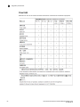
China RoHS . . . . . . . . . . . . . . . . . . . . . . . . . . . . . . . . . . . . . . . . .64

vi Dell PowerConnect B-Series TI24X Hardware Installation Guide
53-1002265-01
Appendix C Caution and Danger Notices
Cautions. . . . . . . . . . . . . . . . . . . . . . . . . . . . . . . . . . . . . . . . . . . . . . . .65
Danger . . . . . . . . . . . . . . . . . . . . . . . . . . . . . . . . . . . . . . . . . . . . . . . . .68

Dell PowerConnect B-Series TI24X Hardware Installation Guide vii
53-1002265-01
About This Document
In this chapter
•Audience. . . . . . . . . . . . . . . . . . . . . . . . . . . . . . . . . . . . . . . . . . . . . . . . . . . . . . vii
•Supported hardware and software. . . . . . . . . . . . . . . . . . . . . . . . . . . . . . . . . vii
•Document conventions . . . . . . . . . . . . . . . . . . . . . . . . . . . . . . . . . . . . . . . . . . vii
•Related publications . . . . . . . . . . . . . . . . . . . . . . . . . . . . . . . . . . . . . . . . . . . . . ix
•Getting technical help or reporting errors . . . . . . . . . . . . . . . . . . . . . . . . . . . . ix
•Contacting Dell . . . . . . . . . . . . . . . . . . . . . . . . . . . . . . . . . . . . . . . . . . . . . . . . . ix
Audience
This manual is designed for system administrators with a working knowledge of Layer 2 and Layer 3
switching and routing.
You should be familiar with the following protocols if applicable to your network – IP, RIP, OSPF,
IS-IS, BGP4, MBGP, IGMP, PIM, DVMRP, FSRP, VRRP, and VRRPE.
Supported hardware and software
The following hardware platform is supported by this release of this guide:
• PowerConnect B-Series TI24X Series
Document conventions
This section describes text formatting conventions and important notice formats used in this
document.

viii Dell PowerConnect B-Series TI24X Hardware Installation Guide
53-1002265-01
Text formatting
The narrative-text formatting conventions that are used are as follows:
For readability, command names in the narrative portions of this guide are presented in bold: for
example, show version.
.
Command syntax conventions
Command syntax in this manual follows these conventions:
Notes, cautions, and danger notices
The following notices and statements are used in this manual. They are listed below in order of
increasing severity of potential hazards.
NOTE
A note provides a tip, guidance or advice, emphasizes important information, or provides a reference
to related information.
bold text Identifies command names
Identifies the names of user-manipulated GUI elements
Identifies keywords
Identifies text to enter at the GUI or CLI
italic text Provides emphasis
Identifies variables
Identifies document titles
code text Identifies CLI output
command and
parameters
Commands and parameters are printed in bold.
[ ] Optional parameter.
variable Variables are printed in italics enclosed in angled brackets < >.
... Repeat the previous element, for example “member[;member...]”
| Choose from one of the parameters.

Dell PowerConnect B-Series TI24X Hardware Installation Guide ix
53-1002265-01
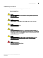
CAUTION
A Caution statement alerts you to situations that can be potentially hazardous to you or cause
damage to hardware, firmware, software, or data.
DANGER
A Danger statement indicates conditions or situations that can be potentially lethal or extremely
hazardous to you. Safety labels are also attached directly to products to warn of these conditions
or situations.
Related publications
The following Dell documents supplement the information in this guide:
• PowerConnect B-SeriesTI24X Configuration Guide
• PowerConnect B-MLXe MIB Reference
NOTE
For the latest edition of this document, which contains the most up-to-date information, refer to
support.dell.com.
Getting technical help or reporting errors
Dell is committed to ensuring that your investment in our products remains cost-effective. If you
need assistance or find errors in the manuals, contact Dell Technical Support. When contacting
Dell Technical Support have the device configuration file and an output capture of show
tech-support command available.
Contacting Dell
For customers in the United States, call 800-WWW.DELL (800.999.3355).
NOTE
If you do not have an active Internet connection, you can find contact information on your purchase
invoice, packing slip, bill, or Dell product catalog.
Dell provides several online and telephone-based support and service options. Availability varies by
country and product, and some services may not be available in your area. To contact Dell for sales,
technical support, or customer service issues:

x Dell PowerConnect B-Series TI24X Hardware Installation Guide
53-1002265-01
1. Visit http://support.dell.com.
2. Click your country or region at the bottom of the page. For a full listing of countries and regions,
click All.
3. In the Support menu, click All Support.
4. Choose the method of contacting Dell that is convenient for you.

Dell PowerConnect B-Series TI24X Hardware Installation Guide 1
53-1002265-01
Chapter
1
Product Overview
In this chapter
•Product overview . . . . . . . . . . . . . . . . . . . . . . . . . . . . . . . . . . . . . . . . . . . . . . . . 1
•Software features . . . . . . . . . . . . . . . . . . . . . . . . . . . . . . . . . . . . . . . . . . . . . . . 1
•Hardware features. . . . . . . . . . . . . . . . . . . . . . . . . . . . . . . . . . . . . . . . . . . . . . . 1
Product overview
PowerConnect B-Series TI24X provides high port density and 512 MB of DDR RAM when shipped
from the factory. PowerConnect B-Series TI24X delivers a full complement of standards-based,
feature-rich Layer 2 switching capability. The extensive feature set supports network requirements
ranging from basic connectivity to multicast- enabled full streaming audio and video applications
for converged services.
The PowerConnect B-Series TI24X supports:
• Twenty-four SFP+ ports at either 1 GbE or 10 GbE using the standard E1MG optics, as well as
the new SFP+ 10GbE optics
• Four 10/100/1000 RJ-45 ports
Software features
Software features differ depending on the software version that is loaded on the device. When first
shipped, the PowerConnect B-Series TI24X devices support full Layer 2 Switching.
For a complete list of software features supported on the PowerConnect, refer to the release notes
or the PowerConnect B-Series TI24X Configuration Guide.
Hardware features
This section describes the physical characteristics of the PowerConnect B-Series TI24X models. For
details about physical dimensions, power supply specifications, and pin-outs, refer to Appendix A,
“Hardware Specifications”.

2 Dell PowerConnect B-Series TI24X Hardware Installation Guide
53-1002265-01
Hardware features
1
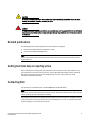
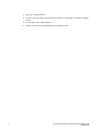
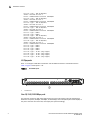
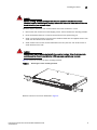
Figure 1 shows the PowerConnect B-Series TI24X.
FIGURE 1 PowerConnect B-Series TI24X
PowerConnect B-Series TI24X contains the following ports:
• Twenty-four (24) SFP+ 10 Gigabit and Gigabit Ethernet fiber ports
• Four (4) 10/100/1000 Mbps copper ports, supporting 100Base-TX and 1000Base-T RJ-45
connectors
Control features
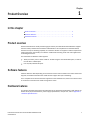
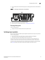
PowerConnect B-Series TI24X front panel has the following control features:
• Serial management interface-DB-9 connector interface (Console Port)
• 10/100/1000 RJ-45 Management Port
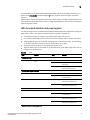
FIGURE 2 Console and management ports
Serial management interface (Console port)
The serial management interface (port labeled Console) enables you to configure and manage the
device using a third-party terminal emulation application on a directly-connected PC,
straight-through EIA or TIA DB-9 serial cable (M/F) is included. The console port is located in the
upper right of the front panel.
1 Management Port 2 Console Port
A
1
2

Dell PowerConnect B-Series TI24X Hardware Installation Guide 3
53-1002265-01
Hardware features
1
Management port
The Management port provides connectivity to your existing management network through
10/100/1000 copper ports that uses auto-sensing and auto-negotiating to determine the speed
(10 Mbps, 100 Mbps, or 1000 Mbps) and mode (full-duplex or half-duplex) of the port at the other
end of the link, and adjusts port speed accordingly. The Management port on the PowerConnect
B-Series TI24X supports RJ-45 copper connectors, auto MDI or MDIX detection, and has an RJ-45
unshielded twisted pair (UTP) connector.
NOTE
This port interfaces with the CPU only and not the data plane.
Network interfaces
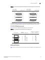
Table 1 describes the network interfaces supported on PowerConnect B-Series TI24X devices. For
network interface specifications, refer to Table 12 on page 54.
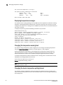
Viewing the media types installed in the ports
The show media command displays the types of media (copper or fiber) installed in the ports. The
following example is show media output.
PowerConnect# show media
Port 1: Type : 10G XG-SR(SFP+)
Vendor: Brocade Version: 1
Part# : PLRXPLSCS4371 Serial#: C833UQ06H
Port 2: Type : EMPTY
Port 3: Type : EMPTY
Port 4: Type : EMPTY
Port 5: Type : EMPTY
Port 6: Type : 10G XG-SR(SFP+)
Vendor: Brocade Version: 1
Part# : PLRXPLSCS4371 Serial#: C847UQ04C
Port 7: Type : 10G XG-SR(SFP+)
Vendor: Brocade Version: 1
Part# : PLRXPLSCS4371 Serial#: C847UQ04H
Port 8: Type : EMPTY
Port 9: Type : EMPTY
Port 10: Type : EMPTY
Port 11: Type : EMPTY
Port 12: Type : EMPTY
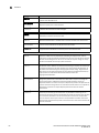
TABLE 1 Optics for Network Interfaces
Interface Show Media Description
1000Base-BX-D M-GBXD
1000Base-BX-U M-GBXU
1000Base-LHA M-LHA
1000Base-LX M-LX
1000Base-SX M-SX
10GBase-LR XG-LR
10GBase-SR XG-SR

4 Dell PowerConnect B-Series TI24X Hardware Installation Guide
53-1002265-01
Hardware features
1
Port 13: Type : 10G XG-SR(SFP+)
Vendor: Brocade Version: 1
Part# : PLRXPLSCS4371 Serial#: C847UQ04T
Port 14: Type : 10G XG-SR(SFP+)
Vendor: Brocade Version: 1
Part# : PLRXPLSCS4371 Serial#: C847UQ04R
Port 15: Type : 10G XG-SR(SFP+)
Vendor: Brocade Version: 1
Part# : PLRXPLSCS4371 Serial#: C847UQ050
Port 16: Type : 10G XG-SR(SFP+)
Vendor: Brocade Version: 1
Part# : PLRXPLSCS4371 Serial#: C847UQ059
Port 17: Type : EMPTY
Port 18: Type : EMPTY
Port 19: Type : 10G XG-SR(SFP+)
Vendor: Brocade Version: 1
Part# : PLRXPLSCS4371 Serial#: C847UQ04K
Port 20: Type : 10G XG-SR(SFP+)
Vendor: Brocade Version: 1
Part# : PLRXPLSCS4371 Serial#: C833UQ068
Port 21: Type : EMPTY
Port 22: Type : EMPTY
Port 23: Type : EMPTY
Port 24: Type : EMPTY
Port 25: Type : 1G M-C (Gig-Copper)
Port 26: Type : 1G M-C (Gig-Copper)
Port 27: Type : 1G M-C (Gig-Copper)
Port 28: Type : 1G M-C (Gig-Copper)
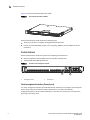
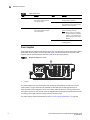
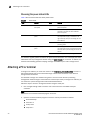
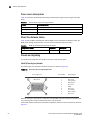
10 Gbps ports
Ports 1 - 24 support 1-GbE SFP transceivers and 10-GbE SFP and SFP+ transceivers listed in
Table 1. Figure 3 shows ports 1 - 24.
FIGURE 3 24 10-GbE ports
Four 10/100/1000 Mbps ports
The ports 25~28 are 10/100/1000 copper ports that use auto-sensing and auto-negotiating to
determine the speed (10 Mbps, 100 Mbps, or 1000 Mbps) and mode (full-duplex or half-duplex) of
the port at the other end of the link, and adjust port speed accordingly.
110-GbE Ports
A
1

Dell PowerConnect B-Series TI24X Hardware Installation Guide 5
53-1002265-01
Hardware features
1
10/100/1000 ports on the PowerConnect B-Series TI24X support RJ-45 copper connectors. The
output of the show media command displays C next to the ports that have copper connectors
installed.
Gigabit copper ports on the PowerConnect B-Series TI24X support auto MDI or MDIX detection. For
more information about this feature, refer to "Configuring MDI/MDIX" in the PowerConnect B-Series
TI24X Configuration Guide.
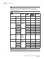
LEDs for network interfaces and power supplies
The fiber and copper ports on PowerConnect B-Series TI24X provide status information through the
LEDs listed in Table 2. The LEDs for network interfaces and power supplies are:
• 24 10-Gbps fiber ports (1~24 port) have LEDs located under each of them.
• Four 10/100/1000 copper ports (25~28) have Link and Activity LEDs to indicate port status.
• The Management port has a Link LED and Activity LED to indicate port status. The Link LED is
on the left of the copper connector and the Activity LED is on the right.
• The System power on LED is on the left side of the front panel.
• The dual power supply 1 and 2 LEDs are on the front panel of the power supply (when you are
facing the rear of the device).
.
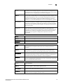
TABLE 2 LEDs
LEDs Position State Meaning
10Gbps Port LEDs
LNK or ACT Located under the 10-GbE
ports
On The port is connected.
Off No fiber port connection exists or the
link is down.
Blinking Traffic is begin transmitted or
received on the fiber port.
10/100/1000 Copper Port LEDs
Lnk This is the left LED on RJ45 On The port is connected.
Off No copper port connection exists or
the link is down.
Act This is the right LED on RJ45 On or Blinking Traffic is being transmitted or
received on the copper port.
Off No traffic is being transmitted or
received on the copper port.
Management Port LEDs
Lnk This is the left LED on RJ45 On The port is connected.
Off No copper port connection exists or
the link is down.
Act This is the right LED on RJ45 On or Blinking Traffic is being transmitted or
received on the copper port.
Off No traffic is being transmitted or
received on the copper port.
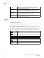
System Power and Power Supply LEDs

6 Dell PowerConnect B-Series TI24X Hardware Installation Guide
53-1002265-01
Hardware features
1
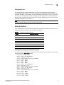
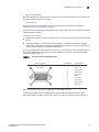
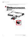
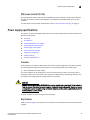
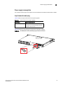
Power supplies
Each PowerConnect B-Series TI24X device comes with dual alternating-current (AC) power supplies
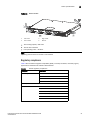
(RPS-TI24X). Power supplies are hot-swappable.Figure 4 shows the front panel of the AC power
supplies used in the PowerConnect B-Series TI24X (at the rear of the device).
FIGURE 4 AC power supply front panel
The power supplies are auto-sensing and auto-switching, and provide up to 300 watts of total
output power, having a universal input (100 VAC to 240 VAC) and 12 VDC regulated output.
Power supplies can be swapped in or out of the device while the device is running, and without
opening the device. You can remove one of the supplies without interrupting operation because the
remaining power supply provides enough power for all of the ports.
For power supply hardware specifications, refer to “Power supply specifications” on page 55.
Power On the upper left side of the
front panel (when facing the
front of the device)
On The device is powered on and has
enough power to operate.
Off The device is not powered on, or has
been powered on but does not have
sufficient power to operate.
AC OK Upper center of power supply's
front panel (when facing the
rear of the device)
On Indicated power supply is installed
and is functioning normally.
NOTE: Power supply 1 is located in
the right-hand bay and power
supply 2 in the left-hand bay
(when facing the rear of the
device).
Off Power supply is not installed or is not
providing power.
1AC LED
TABLE 2 LEDs (Continued)
LEDs Position State Meaning
1

Dell PowerConnect B-Series TI24X Hardware Installation Guide 7
53-1002265-01
Hardware features
1
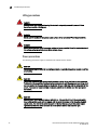
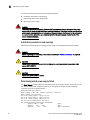
CAUTION
Disconnect the power supply cable from the power source (outlet) before you install it in or
remove it from the device. Failure to do this can result in damage to the power supply or the
device, or both (the device can be running while a power supply is being installed or removed, but
the power supply itself should not be connected to a power source).

8 Dell PowerConnect B-Series TI24X Hardware Installation Guide
53-1002265-01
Hardware features
1

Dell PowerConnect B-Series TI24X Hardware Installation Guide 9
53-1002265-01
Chapter
2
Installing the PowerConnect B-Series TI24X
In this chapter
•Unpacking a system . . . . . . . . . . . . . . . . . . . . . . . . . . . . . . . . . . . . . . . . . . . . . 9
•Summary of installation tasks . . . . . . . . . . . . . . . . . . . . . . . . . . . . . . . . . . . . 10
•Installation precautions . . . . . . . . . . . . . . . . . . . . . . . . . . . . . . . . . . . . . . . . . 11
•Preparing the installation site. . . . . . . . . . . . . . . . . . . . . . . . . . . . . . . . . . . . . 15
•Installing the device . . . . . . . . . . . . . . . . . . . . . . . . . . . . . . . . . . . . . . . . . . . . 15
•Powering on the system . . . . . . . . . . . . . . . . . . . . . . . . . . . . . . . . . . . . . . . . . 18
•Verifying proper operation. . . . . . . . . . . . . . . . . . . . . . . . . . . . . . . . . . . . . . . . 19
•Attaching a PC or terminal . . . . . . . . . . . . . . . . . . . . . . . . . . . . . . . . . . . . . . . 20
Unpacking a system
DANGER
The procedures in this manual are intended for qualified service personnel.
Information about configuring IP addresses and connecting network devices is in the Chapter 3,
“Connecting Network Devices and Checking Connectivity”.
Dell PowerConnect systems ship with all of the items listed below. Please review the list and verify
the contents. If any items are missing, please contact the place of purchase.
Package contents
Verify the package contents listed below:
• Dell PowerConnect B-Series TI24X device with dual AC power supplies installed
• AC PDU power cords (C13-C14)
• Document kit
• Retainer nuts and screws
• Rubber feet
• Rack mount kit (includes rack mount brackets, retainer nuts and screws)

10 Dell PowerConnect B-Series TI24X Hardware Installation Guide
53-1002265-01
Summary of installation tasks
2
General requirements
To manage the system, you will need the following items for serial connection to a Layer 2 or Layer
3 switch:
• A management station, such as a PC running a terminal emulation application.
• A straight-through EIA or TIA DB-9 serial cable (F/F). If you prefer to build your own cable, refer
to the pinout information in “Attaching a PC or terminal” on page 20.
• Use the serial connection to perform basic configuration tasks, such as assigning an IP
address and network mask. This information is required to manage the system using the
Brocade Network Advisor or using the CLI through Telnet.
Summary of installation tasks
Follow the steps listed below to install your PowerConnect B-Series TI24X device. Details for each
of these steps are provided in this chapter and in the following chapter.
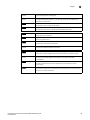
TABLE 3 Summary of installation tasks
Task No. Task Where to Find More Information
1 Ensure that the physical environment where the device will be
installed has the proper cabling and ventilation.
“Preparing the installation site”
on page 15
2 Install the Dell PowerConnect device on a desktop or in an
equipment rack. Devices may also be wall-mounted.
“Installing the device” on
page 15
3 When the device is installed, plug the PDU power cords (C13-C14)
into a nearby power source that adheres to the regulatory
requirements outlined in this manual.
“Powering on the system” on
page 18
4 Verify that power LED is on after the system is powered-on. “Verifying proper operation” on
page 19
5 Attach a terminal or PC to the Dell PowerConnect device. This
enables you to configure the device through the Command Line
Interface (CLI).
“Attaching a PC or terminal” on
page 20
6 No default password is assigned to the CLI. For additional access
security, assign a password.
“Assigning permanent
passwords” on page 23
7 Before attaching equipment to the device, you must configure an
interface IP address to the subnet on which it will be located. Initial
IP address configuration is performed using the CLI with a direct
serial connection.
“Configuring IP addresses” on
page 25
8 Once you power-on the device and assign IP addresses, the system
is ready to accept network equipment.
“Connecting network devices”
on page 26
9 Test IP connectivity by pinging other devices and tracing routes. “Testing connectivity” on
page 29
10 Continue configuration using the CLI. You also can use Brocade
Network Advisor to manage the device.
PowerConnect B-Series TI24X
Configuration Guide
11 Secure access to the device. PowerConnect B-Series TI24X
Configuration Guide
La page est en cours de chargement...
La page est en cours de chargement...
La page est en cours de chargement...
La page est en cours de chargement...
La page est en cours de chargement...
La page est en cours de chargement...
La page est en cours de chargement...
La page est en cours de chargement...
La page est en cours de chargement...
La page est en cours de chargement...
La page est en cours de chargement...
La page est en cours de chargement...
La page est en cours de chargement...
La page est en cours de chargement...
La page est en cours de chargement...
La page est en cours de chargement...
La page est en cours de chargement...
La page est en cours de chargement...
La page est en cours de chargement...
La page est en cours de chargement...
La page est en cours de chargement...
La page est en cours de chargement...
La page est en cours de chargement...
La page est en cours de chargement...
La page est en cours de chargement...
La page est en cours de chargement...
La page est en cours de chargement...
La page est en cours de chargement...
La page est en cours de chargement...
La page est en cours de chargement...
La page est en cours de chargement...
La page est en cours de chargement...
La page est en cours de chargement...
La page est en cours de chargement...
La page est en cours de chargement...
La page est en cours de chargement...
La page est en cours de chargement...
La page est en cours de chargement...
La page est en cours de chargement...
La page est en cours de chargement...
La page est en cours de chargement...
La page est en cours de chargement...
La page est en cours de chargement...
La page est en cours de chargement...
La page est en cours de chargement...
La page est en cours de chargement...
La page est en cours de chargement...
La page est en cours de chargement...
La page est en cours de chargement...
La page est en cours de chargement...
La page est en cours de chargement...
La page est en cours de chargement...
La page est en cours de chargement...
La page est en cours de chargement...
La page est en cours de chargement...
La page est en cours de chargement...
La page est en cours de chargement...
La page est en cours de chargement...
La page est en cours de chargement...
La page est en cours de chargement...
La page est en cours de chargement...
La page est en cours de chargement...
-
 1
1
-
 2
2
-
 3
3
-
 4
4
-
 5
5
-
 6
6
-
 7
7
-
 8
8
-
 9
9
-
 10
10
-
 11
11
-
 12
12
-
 13
13
-
 14
14
-
 15
15
-
 16
16
-
 17
17
-
 18
18
-
 19
19
-
 20
20
-
 21
21
-
 22
22
-
 23
23
-
 24
24
-
 25
25
-
 26
26
-
 27
27
-
 28
28
-
 29
29
-
 30
30
-
 31
31
-
 32
32
-
 33
33
-
 34
34
-
 35
35
-
 36
36
-
 37
37
-
 38
38
-
 39
39
-
 40
40
-
 41
41
-
 42
42
-
 43
43
-
 44
44
-
 45
45
-
 46
46
-
 47
47
-
 48
48
-
 49
49
-
 50
50
-
 51
51
-
 52
52
-
 53
53
-
 54
54
-
 55
55
-
 56
56
-
 57
57
-
 58
58
-
 59
59
-
 60
60
-
 61
61
-
 62
62
-
 63
63
-
 64
64
-
 65
65
-
 66
66
-
 67
67
-
 68
68
-
 69
69
-
 70
70
-
 71
71
-
 72
72
-
 73
73
-
 74
74
-
 75
75
-
 76
76
-
 77
77
-
 78
78
-
 79
79
-
 80
80
-
 81
81
-
 82
82


Dell PowerConnect B-TI24x Guide de démarrage rapide
- Taper
- Guide de démarrage rapide
dans d''autres langues
Documents connexes
-
Dell S4112F 1.1 Mode d'emploi
-
Dell PowerConnect B-TI24x Guide d'installation
-
-
Dell PowerConnect 2508 Mode d'emploi
-
-
-
-
-
-
Autres documents
-
Brocade Communications Systems 53-1002580-01 Manuel utilisateur
-
SMC Networks 8150L2 Manuel utilisateur
-
-
-
 Ditel KOS569 Technical Manual
-
LG-Ericsson ipecs ES-5048XG Guide d'installation
-
red lion NT328G Hardware Manuel utilisateur
-
-
Motorola EX-3524 Guide d'installation
-
 AmazonBasics B07ZTQY9DD Manuel utilisateur

