
FA01802M4A
88001-0261
IT Italiano
EN English
FR Français
RU Русский
CAME S.p.A.
Via Martiri della
Libertà, 15
31030 Dosson di Casier
Treviso - Italy
Tel. (+39) 0422 4940
Fax (+39) 0422 4941
ITALIANO
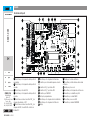
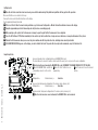
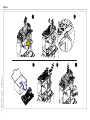
Descrizione delle parti
1 Morsettiera per il collegamento dei dispositivi di
segnalazione
2 Morsettiera per il collegamento dei dispositivi di
comando
3 Morsettiera per l'uscita B1-B2
4 Morsettiera per il collegamento dei dispositivi di
sicurezza
5 Morsettiera associata al connettore RSE_1 per
collegamento abbinato o CRP
6 Morsettiera associata al connettore RSE_2 per
collegamento CRP, scheda IO 485 o interfaccia
Modbus RTU
7 Morsettiera per il collegamento dell'antenna
8 Connettore per scheda radiofrequenza a innesto
(AF)
9 Connettore RSE_2 per scheda RSE
10 Connettore RSE_1 per scheda RSE
11 Connettore per CAME KEY
12 Tasti per la programmazione
13 Morsettiera per il collegamento del motoriduttore
14 Morsettiera per il collegamento dell'Encoder
15 Display
16 Fusibile per la scheda elettronica
17 Morsettiera per l'alimentazione della scheda
elettronica
18 Fusibile per gli accessori
19 Morsettiera per il collegamento dei fi necorsa
20 Connettore per scheda Memory Roll
21 Connettore per scheda CLOCK
22 Morsettiera per accessori BUS
23 Connettore per modulo RIOCN8WS
FA01802M4A - 04/2022
88001-0261

2 - FA01802M4A - 04/2022 - © CAME S.p.A.
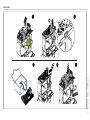
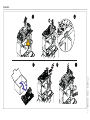
Installazione

3 - FA01802M4A - 04/2022 - © CAME S.p.A.
Programmazione
Per la programmazione completa consultare il fascicolo tecnico di 801MS-0570/801MS-0580/801MS-0590 su www.came.com ( > documentazione tecnica).
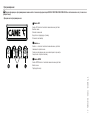
Funzione dei tasti di programmazione
Esc < > Ent
1 Tasto ESC
Il tasto ESC permette di eseguire le operazioni di seguito descritte.
Uscire dal menu
Annullare le modifi che
Tornare alla schermata precedente
Arrestare l'automazione
2 Tasti < >
I tasti < > permettono di eseguire le operazioni di seguito descritte.
Navigare attraverso le voci del menu
Incrementare o decrementare un valore
Chiudere o aprire l'automazione
3 Tasto ENTER
Il tasto ENTER permette di eseguire le operazioni di seguito descritte.
Entrare nei menu
Confermare la scelta

4 - FA01802M4A - 04/2022 - © CAME S.p.A.
Messa in funzione
Terminati i collegamenti elettrici, procedere con la messa in funzione. L'operazione deve essere e ettuata solo da personale esperto e qualifi cato.
Controllare che l’area di manovra sia libera da qualsiasi ostacolo.
Dare tensione e procedere con le indicazioni a display.
Iniziare la programmazione seguendo la PROCEDURA GUIDATA.
Se non è la prima accensione della scheda, entrare nel menu Confi gurazione > Procedura guidata. Seguire successivamente le indicazioni a display.
Completata la programmazione, controllare il buon funzionamento dei dispositivi di segnalazione e di sicurezza.
Dopo aver dato tensione all’impianto, la prima manovra è sempre in apertura; attendere il completamento della manovra.
Premere immediatamente il tasto ESC o il pulsante di STOP se si riscontrano anomalie, malfunzionamenti, rumorosità o vibrazioni sospette o comportamenti inattesi
dell’impianto.
E ettuare la prima manovra con movimentazione in vista e fotocellule attive, anche con comando da remoto.
Se sul display compare la scritta NECESSARIA TARATURA, è indispensabile eseguire la taratura della corsa. Il quadro non accetterà comandi di movimentazione ad esclusione
della prova motore.
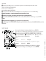
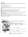
Esportare / importare dati
È possibile salvare i dati relativi agli utenti e alla confi gurazione dell'impianto in una scheda MEMORY ROLL.
I dati memorizzati possono essere riutilizzati in un'altra scheda elettronica dello stesso tipo per riportare le stesse confi gurazioni.
Prima di inserire ed estrarre la scheda MEMORY ROLL, è OBBLIGATORIO TOGLIERE LA TENSIONE DI LINEA.
1 Inserire la scheda MEMORY ROLL sul
connettore dedicato presente sulla scheda
elettronica.
2 Premere il pulsante Enter per accedere
alla programmazione.
3 Usare le frecce per scegliere la
funzione desiderata.
Confi gurazione > Memoria esterna > Salvataggio dati
Salva nel dispositivo di memoria (memory roll) i dati relativi agli utenti, alle temporizzazioni e alle confi gurazioni.
Confi gurazione > Memoria esterna > Lettura dati
Carica dal dispositivo di memoria (memory roll) i dati relativi agli utenti, alle temporizzazioni e alle confi gurazioni.
Terminate le operazioni di salvataggio e caricamento dati è possibile rimuovere la MEMORY ROLL.

5 - FA01802M4A - 04/2022 - © CAME S.p.A.
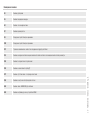
Messaggi di errore
E2 Errore di calibrazione
E3 Errore rottura encoder
E4 Errore di test servizi fallito
E7 Errore tempo di lavoro
E9 Ostacolo rilevato durante la chiusura
E10 Ostacolo rilevato durante l'apertura
E11 Superato il numero massimo di ostacoli rilevati consecutivamente
E13 Errore su ingressi fi necorsa o fi necorsa entrambi aperti
E14 Errore comunicazione seriale
E15 Errore trasmettitore non compatibile
E17 Errore sistema wireless non comunica
E18 Errore sistema wireless non confi gurato
E24 Errore di comunicazione con i dispositivi BUS
E25 Errore di impostazione indirizzi sui dispositivi BUS

6 - FA01802M4A - 04/2022 - © CAME S.p.A.
ENGLISH
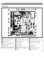
Description of parts
1 Terminal board for connecting the signalling devices
2 Terminal board for connecting control devices
3 Terminal board for B1-B2 output
4 Terminal board for connecting the safety devices
5 Terminal block associated with the RSE_1 connector for
paired or CRP connection
6 Terminal board associated with the RSE_2 connector for
CRP connection, IO 485 card or Modbus RTU interface
7 Terminal board for connecting the antenna
8 Connector for plug-in radio frequency card (AF)
9 RSE_2 connector for RSE card
10 RSE_1 connector for RSE card
11 Connector for CAME KEY
12 Programming buttons
13 Terminal board for connecting the gearmotor
14 Terminal board for connecting the encoder
15 Display
16 Control board fuse
17 Terminal board for power supply to the control board
18 Accessories fuse
19 Terminal board for connecting the limit switches
20 Memory Roll card connector
21 Connector for the CLOCK card
22 Terminal board for BUS accessories
23 Connector for the RIOCN8WS module

7 - FA01802M4A - 04/2022 - © CAME S.p.A.
Installation

8 - FA01802M4A - 04/2022 - © CAME S.p.A.
Programming
For full programming information, please see the technical manual 801MS-0570/801MS-0580/801MS-0590 at www.came.com ( > Tech Docs).
Programming button functions
Esc < > Ent
1 ESC button
The ESC button is used to perform the operations described below.
Exit the menu
Delete the changes
Go back to the previous screen
Stop the operator
2 < > buttons
The <> buttons are used to perform the operations described below.
Navigate the menu
Increase or decrease values
Open or close the operator
3 ENTER button
The ENTER button is used to perform the operations described below.
Access menus
Confi rm choice

9 - FA01802M4A - 04/2022 - © CAME S.p.A.
Getting started
Once the electrical connections have been made, proceed with commissioning. Only skilled and qualifi ed sta may perform this operation.
Make sure that there are no obstacles in the way.
Power up the device and follow the instructions on the display.
Start programming following the wizard.
If this is not the fi rst time the board is being switched on, go to the menu Confi guration > Wizard. Follow the indications shown on the display.
Complete programming and check the warning and safety devices are working properly.
After powering up the system, the fi rst manoeuvre is always to open the gate Wait for the manoeuvre to be completed.
Press the ESC button or STOP button immediately in the event of any faults, malfunctions, strange noises or vibrations, or unexpected behaviour in the system.
Perform the fi rst manoeuvre where you can see the gate in motion and with the photocells active, including where remotely controlled.
If CALIBRATION REQUIRED appears on the display, you must calibrate the travel. The panel will not accept motion commands, except for the motor test.
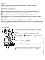
Import/export data
Save user data and system confi guration data on a MEMORY ROLL card.
The stored data can be reused for another control board of the same type to carry across the same confi guration.
Before inserting and removing the MEMORY ROLL card, DISCONNECT THE MAINS POWER SUPPLY TO THE LINE.
1 Insert the MEMORY ROLL card into the
corresponding connector on the control
board.
2 Press the “Enter” button to access
programming.
3 Use the arrows to choose the desired
function.
Confi guration > External memory > Save data
Save user data, timings and confi gurations to the memory device (memory roll).
Confi guration > External memory > Read data
Upload user data, timings and confi gurations to the memory device (memory roll).
Once the data have been saved and loaded, the MEMORY ROLL can be removed.

10 - FA01802M4A - 04/2022 - © CAME S.p.A.
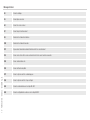
Error messages
E2 Calibration error
E3 Encoder failure error
E4 Service test failure error
E7 Operating time error
E9 Obstacle detected during closing
E10 Obstacle detected during opening
E11 The maximum number of obstacles detected consecutively has been exceeded
E13 Limit switch input error or both limit switches open
E14 Serial communication error
E15 Incompatible transmitter error
E17 Wireless system communication error
E18 Wireless system not confi gured error
E24 BUS device communication error
E25 Address settings error on BUS devices

11 - FA01802M4A - 04/2022 - © CAME S.p.A.
FRANÇAIS
Description des parties
1 Bornier de connexion des dispositifs de signalisation
2 Bornier de connexion des dispositifs de commande
3 Bornier pour la sortie B1-B2
4 Bornier de connexion des dispositifs de sécurité
5 Bornier associé au connecteur RSE_1 pour la connexion
Vis-à-vis ou CRP
6 Bornier associé au connecteur RSE_2 pour connexion CRP,
carte IO 485 ou interface Modbus RTU
7 Bornier de connexion de l’antenne
8 Connecteur pour carte radiofréquence enfi chable (AF)
9 Connecteur RSE_2 pour carte RSE
10 Connecteur RSE_1 pour carte RSE
11 Connecteur pour CAME KEY
12 Touches de programmation
13 Bornier de connexion du motoréducteur
14 Bornier de connexion de l’encodeur
15 A cheur
16 Fusible pour la carte électronique
17 Bornier pour l'alimentation de la carte électronique
18 Fusible pour les accessoires
19 Bornier de connexion des butées de fi n de course
20 Connecteur pour carte Memory Roll
21 Connecteur pour carte CLOCK
22 Bornier pour accessoires BUS
23 Connecteur pour module RIOCN8WS

12 - FA01802M4A - 04/2022 - © CAME S.p.A.
Installation

13 - FA01802M4A - 04/2022 - © CAME S.p.A.
Programmation
Pour la programmation complète, consulter le manuel technique de 801MS-0570/801MS-0580/801MS-0590 sur www.came.com (> documentation technique).
Fonction des touches de programmation
Esc < > Ent
1 Touche ESC
La touche ESC permet d’e ectuer les opérations décrites ci-après.
Sortir du menu
Annuler les modifi cations
Revenir à la page-écran précédente
Arrêter l’automatisme
2 Touches < >
Les touches <> permettent d’e ectuer les opérations décrites ci-après.
Naviguer dans les options du menu
Augmenter ou diminuer une valeur
Fermer ou ouvrir l’automatisme
3 Touche ENTER
La touche ENTER permet d’e ectuer les opérations décrites ci-après.
Entrer dans les menus
Confi rmer le choix

14 - FA01802M4A - 04/2022 - © CAME S.p.A.
Mise en fonction
Au terme des branchements électriques, e ectuer la mise en marche. L’opération ne doit être e ectuée que par du personnel qualifi é et spécialisé.
S'assurer que la zone de manœuvre ne présente aucun obstacle.
Mettre sous tension et suivre les indications a chées à l'écran.
Commencer la programmation en suivant la PROCÉDURE GUIDÉE.
S'il ne s'agit pas de la première activation de la carte, aller dans le menu Confi guration > Procédure guidée. Suivre ensuite les indications a chées à l'écran.
Au terme de la programmation, contrôler le bon fonctionnement des dispositifs de signalisation et de sécurité.
Après avoir mis l'installation sous tension, la première manœuvre a toujours lieu en ouverture; attendre l’exécution complète de la manœuvre.
Appuyer immédiatement sur la touche ESC ou le bouton d'ARRÊT (STOP) en cas d’anomalies, mauvais fonctionnements, bruit, vibrations suspectes ou comportements
imprévus de l’installation.
E ectuer la première manœuvre avec mouvement bien en vue et photocellules activées, y compris avec la commande à distance.
Si l'écran a che le message «AUTO-APPRENTISSAGE NÉCESSAIRE», il faut absolument e ectuer l'auto-apprentissage de la course. L'armoire n'acceptera aucune commande
de mouvement à l'exception du test moteur.
Exporter / importer les données
Il est possible d’enregistrer les données des utilisateurs et de la confi guration de l'installation dans une carte MEMORY ROLL.
Les données stockées peuvent être réutilisées dans une autre carte électronique du même genre pour adopter les mêmes
confi gurations.
Avant d'installer et d’extraire la carte MEMORY ROLL, il est OBLIGATOIRE DE METTRE HORS TENSION.
1 Insérer la carte MEMORY ROLL sur le
connecteur dédié sur la carte électronique.
2 Appuyer sur le bouton Enter pour
accéder à la programmation.
3 Se servir des fl èches pour choisir la
fonction souhaitée.
Confi guration > Mémoire externe > Sauvegarde des
données
Sauvegarde les données des utilisateurs, de synchronisation et de confi guration sur le périphérique mémoire (memory roll).
Confi guration > Mémoire externe > Lecture données
Télécharge les données des utilisateurs, de synchronisation et de confi guration sur le périphérique mémoire (memory roll).
Au terme des opérations de sauvegarde et de téléchargement des données, enlever la MEMORY ROLL.

15 - FA01802M4A - 04/2022 - © CAME S.p.A.
Messages d'erreur
E2 Erreur de calibrage
E3 Erreur rupture encodeur
E4 Erreur test services échoué
E7 Erreur temps de fonctionnement
E9 Obstacle détecté durant la fermeture
E10 Obstacle détecté durant l’ouverture
E11 Dépassement du nombre maximum d'obstacles détectés consécutivement
E13 Erreur sur les entrées fi n de course ou bien butées de fi n de course toutes deux ouvertes
E14 Erreur communication série
E15 Erreur émetteur incompatible
E17 Erreur le système sans fi l ne communique pas
E18 Erreur le système sans fi l n’est pas confi guré
E24 Erreur de communication avec les dispositifs BUS
E25 Erreur de confi guration des adresses sur les dispositifs BUS

16 - FA01802M4A - 04/2022 - © CAME S.p.A.
РУССКИЙ
Описание компонентов
1 Контакты для подключения сигнальных устройств
2 Контакты подключения устройств управления
3 Клеммная панель выхода B1-B2
4 Контакты подключения устройств безопасности
5 Клеммная колодка разъема RSE_1 для подключения в
синхронном режиме или CRP
6 Клеммная панель разъема RSE_2 для подключения
CRP, платы ввода-вывода 485 или интерфейса Modbus RTU
7 Контакты для подключения антенны
8 Разъем для встраиваемой платы радиоприемника (AF)
9 Разъем RSE_2 для платы RSE
10 Разъем RSE_1 для платы RSE
11 Разъем для CAME KEY
12 Кнопки программирования
13 Клеммная панель для подключения электропривода
14 Клеммная панель для подключения энкодера
15 Дисплей
16 Предохранитель для платы управления
17 Контакты электропитания платы управления
18 Предохранитель для дополнительных устройств
19 Клеммная панель для подключения концевых
выключателей
20 Разъем для карты памяти
21 Разъем для платы CLOCK
22 Клеммная панель для аксессуаров ШИНЫ
23 Разъем для модуля RIOCN8WS

17 - FA01802M4A - 04/2022 - © CAME S.p.A.
Монтаж

18 - FA01802M4A - 04/2022 - © CAME S.p.A.
Программирование
Полную информацию о программировании можно найти в технической документации 801MS-0570/801MS-0580/801MS-0590 на сайте www.came.com (> техническая
документация).
Функции кнопок программирования
Esc < > Ent
1 Кнопка ESC
Кнопка ESC позволяет выполнить нижеописанные действия.
Выйти из меню
Отменить изменения
Вернуться на предыдущую страницу
Остановить автоматику
2 Кнопки < >
Кнопки < > позволяют выполнить нижеописанные действия.
Навигация по пунктам меню
Увеличение или уменьшение значения выбранного параметра
Закрыть или открыть автоматику
3 Кнопка ENTER
Кнопка ENTER позволяет выполнить нижеописанные действия.
Войти в меню
Подтвердить выбор

19 - FA01802M4A - 04/2022 - © CAME S.p.A.
Ввод в эксплуатацию
После выполнения всех электрических подключений переходите к вводу системы в эксплуатацию. Операцию должен выполнять только компетентный и
квалифицированный персонал.
Убедитесь в том, что в зоне действия автоматики отсутствуют препятствия.
Подайте напряжение и следуйте указаниям на дисплее.
Приступите к программированию с помощью МАСТЕРА НАСТРОЙКИ.
Если включение платы происходит не в первый раз, войдите в меню Настройка конфигурации > Мастер настройки. Последовательно выполняйте указания на
дисплее.
После завершения программирования проверьте правильность работы сигнальных устройств и устройств безопасности.
После подачи напряжения на систему ворота вначале всегда открываются; дождитесь завершения хода.
Немедленно нажмите на кнопку ESC или на кнопку «СТОП» при обнаружении неполадок, неисправностей, подозрительного шума или вибрации, а также при
неожиданном поведении системы.
Подайте первую команду при работающих фотоэлементах и с автоматикой в поле зрения, даже с помощью дистанционного управления.
Если на дисплее появляется надпись «ТРЕБУЕТСЯ КАЛИБРОВКА», необходимо выполнить калибровку движения. Блок управления не принимает команды управления
движением без предварительного тестирования привода.
Экспорт / импорт данных
Данные, относящиеся к пользователям и настройкам системы, можно сохранить на КАРТЕ ПАМЯТИ.
Сохраненные данные можно снова использовать повторно на другой плате управления той же модели для установки
аналогичных настроек.
ОТКЛЮЧИТЕ ЭЛЕКТРОПИТАНИЕ перед установкой или извлечением КАРТЫ ПАМЯТИ.
1 Вставьте КАРТУ ПАМЯТИ в
специальный разъем на плате
управления.
2 Нажмите кнопку Enter для перехода к
процедуре программирования.
3 Стрелками выберите желаемую
функцию.
Настройка > Внешняя память > Сохранение данных
Сохраняет в запоминающем устройстве (карте памяти) данные, относящиеся к пользователям, параметрам времени и
настройкам.
Настройка > Внешняя память > Считывание данных
Загружает из запоминающего устройства (карты памяти) данные, относящиеся к пользователям, выдержке времени и
настройкам.
Завершив сохранение и загрузку данных, после чего извлеките КАРТУ ПАМЯТИ.

20 - FA01802M4A - 04/2022 - © CAME S.p.A.
Сообщения об ошибках
E2 Ошибка регулировки
E3 Ошибка повреждения энкодера
E4 Ошибка сбоя самодиагностики
E7 Ошибка времени работы
E9 Обнаружено препятствие при закрывании
E10 Обнаружено препятствие при открывании
E11 Превышено максимальное количество обнаруженных подряд препятствий
E13 Ошибка на входных контактах концевых выключателей или контакты обоих концевых выключателей разомкнуты
E14 Ошибка последовательного подключения
E15 Ошибка несовместимости пульта ДУ
E17 Ошибка отсутствия связи с беспроводной системой
E18 Ошибка не настроенной беспроводной системы
E24 Ошибка связи с ШИННЫМИ устройствами
E25 Ошибка настройки адресов на устройствах ШИНЫ
-
 1
1
-
 2
2
-
 3
3
-
 4
4
-
 5
5
-
 6
6
-
 7
7
-
 8
8
-
 9
9
-
 10
10
-
 11
11
-
 12
12
-
 13
13
-
 14
14
-
 15
15
-
 16
16
-
 17
17
-
 18
18
-
 19
19
-
 20
20


dans d''autres langues
- italiano: CAME 88001-026, ZBC1
Documents connexes
-
CAME 88006-0058, ZLX24S Spare Parts Manual
-
-
-
-
-
-
-
-
-