ANTAIRA LNX-1204G-10G-SFP Manuel utilisateur
- Catégorie
- Commutateurs réseau
- Taper
- Manuel utilisateur
Ce manuel convient également à

LNX-1204G-10G-SFP
12-Port Industrial Gigabit Unmanaged Ethernet Switch, w/8*10/100/1000Tx, 2*1000
SFP Slots, and 2*10G SFP+ Slots
Hardware Manual
Version 1.0
(July 2020)

ii
Antaira Technologies - Industrial Ethernet Switches
LNX-1204G-10G-SFP Hardware Manual V1.0
© Copyright 2020 Antaira Technologies, LLC.
All Rights Reserved
This document contains information, which is protected by copyright. Reproduction, adaptation or translation
without prior permission is prohibited, except as allowed under the copyright laws.
Trademark Information
Antaira is a registered trademark of Antaira Technologies, LLC., Microsoft Windows and the Windows logo are
the trademarks of Microsoft Corp. NetWare is the registered trademark of Novell Inc. WMM and WPA are the
registered trademarks of Wi-Fi Alliance. All other brand and product names are trademarks or registered
trademarks of their respective owners.
Notice: Copyrights © 2020 by Antaira Technologies, LLC. All rights reserved. Reproduction, adaptation, or
translation without prior permission of Antaira Technologies, LLC. is prohibited, except as allowed under the
copyright laws.
Disclaimer
Antaira Technologies, LLC. provides this manual without warranty of any kind, expressed or implied, including but
not limited to the implied warranties of merchantability and fitness for a particular purpose. Antaira Technologies,
LLC. may make improvements and/or changes to the product and/or specifications of the product described in
this manual, without prior notice. Antaira Technologies, LLC. will not be liable for any technical inaccuracies or
typographical errors found in this guide. Changes are periodically made to the information contained herein and
will be incorporated into later versions of the manual. The information contained is subject to change without prior
notice.

iii
Antaira Technologies - Industrial Ethernet Switches
LNX-1204G-10G-SFP Hardware Manual V1.0
FCC Warning
This equipment has been tested and found to comply with the limits for a Class-A digital device, pursuant to Part
15 of the FCC rules. These limits are designed to provide reasonable protection against harmful interference in a
residential installation. This equipment generates, uses, and can radiate radio frequency energy. It may cause
harmful interference to radio communications if the equipment is not installed and used in accordance with the
instructions. However, there is no guarantee that interference will not occur in a particular installation. If this
equipment does cause harmful interference to radio or television reception, which can be determined by turning
the equipment off and on, the user is encouraged to try to correct the interference by one or more of the following
measures:
•
Reorient or relocate the receiving antenna.
•
Increase the separation between the equipment and receiver.
•
Connect the equipment into an outlet on a circuit different from that to which the receiver is connected.
•
Consult the dealer or an experienced radio/TV technician for help.
Caution: Any changes or modifications not expressly approved by the grantee of this device could void the user's
authority to operate the equipment.
Avertissement FCC
Cet équipement a été testé et déclaré conforme aux limites d'un appareil numérique de classe A, conformément
à la partie 15 des règles de la FCC. Ces limites sont conçues pour fournir une protection raisonnable contre les
interférences nuisibles dans une installation résidentielle. Cet équipement génère, utilise et peut émettre de
l'énergie radiofréquence. Cela peut provoquer des interférences nuisibles aux communications radio si
l'équipement n'est pas installé et utilisé conformément aux instructions. Cependant, il n'y a aucune garantie
qu'aucune interférence ne se produira dans une installation particulière. Si cet équipement provoque des
interférences nuisibles à la réception radio ou télévision, ce qui peut être déterminé en éteignant puis en
rallumant l'équipement, l'utilisateur est encouragé à essayer de corriger les interférences par une ou plusieurs
des mesures suivantes:
•
Réorientez ou déplacez l'antenne de réception.
•
Augmentez la distance entre l'équipement et le récepteur.
•
Connectez l'équipement à une prise sur un circuit différent de celui auquel le récepteur est connecté.
•
Consultez le revendeur ou un technicien radio / TV expérimenté pour obtenir de l'aide.
Attention: Tout changement ou modification non expressément approuvé par le bénéficiaire de cet appareil peut
annuler le droit de l'utilisateur à utiliser l'équipement.

iv
Antaira Technologies - Industrial Ethernet Switches
LNX-1204G-10G-SFP Hardware Manual V1.0
CE Mark Warning
This is a Class-A product. In a domestic environment this product may cause radio interference in which case the
user may be required to take adequate measures.
Avertissement de marque CE
Ceci est un produit de classe A. Dans un environnement domestique, ce produit peut provoquer des
interférences radio, auquel cas l'utilisateur peut être amené à prendre des mesures adéquates.
Industrial Ethernet Switches
Industrial Grade Gigabit Unmanaged Ethernet Switches
Hardware Manual
Version 1.0 (July 2020)
This manual supports the following models:
•
LNX-1204G-10G-SFP

v
Antaira Technologies - Industrial Ethernet Switches
LNX-1204G-10G-SFP Hardware Manual V1.0
Table of Contents
1. Introduction ..................................................................... 6
1.1 Product Overview ...................................................................... 6
1.2 Product Hardware Features ...................................................... 6
1.3 Package Contents ..................................................................... 6
1.4 Safety Precaution ...................................................................... 7
2. Hardware Description ...................................................... 8
2.1 Physical Dimensions ................................................................. 8
2.2 Front Panel ................................................................................ 9
2.3 Top View.................................................................................... 9
2.4 LED Indicators ......................................................................... 10
2.5 Ethernet Ports.......................................................................... 10
2.6 Cabling .................................................................................... 11
2.7 Wiring the Power Inputs .......................................................... 12
2.8 Wiring the Fault Alarm Contact ............................................... 13
2.9 Grounding Note ....................................................................... 13
3. Mounting Installation ..................................................... 15
3.1 DIN-Rail Mounting ................................................................... 15
3.2 Wall Mounting .......................................................................... 16
4. Hardware Installation .................................................... 17
4.1 Installation Steps ..................................................................... 17
4.2 Maintenance and Service ........................................................ 18
4.3 Troubleshooting ....................................................................... 18
5.
Technical Specifications ............................................... 19

Antaira Technologies - Industrial Ethernet Switches
LNX-1204G-10G-SFP Hardware Manual V1.0
6
1. Introduction
1.1 Product Overview
Antaira Technologies’ LNX-1204G-10G-SFP are industrial gigabit unmanaged Ethernet switches
featuring 8*10/100/1000Tx Gigabit Ethernet ports, 2*1G SFP slots, and 2*10G SFP+ slots which
provide options for long-distance fiber connections, making it ideal for applications that demand
high bandwidth and long-distance communication.
The LNX-1204G-10G-SFP are IP30 rated and DIN-rail mountable. These Ethernet switches are
designed to support an operating temperature range from -40° to 65°C and are perfect industrial
networking products to support any applications that require high bandwidth or high-density
connections, such as power/utility, water wastewater treatment, oil/gas/mining, process control
automation, security access control systems, and intelligent transportation systems.
1.2 Product Hardware Features
◼ System Interface and Performance
•
All RJ45 ports support Auto MDI/MDI-X Function
•
Embedded 8*10/100/1000Tx RJ45 ports, 2*1G SFP slots, and 2*10G SFP+ slots
•
Store-and-forward switching architecture
•
16K MAC address table
•
Supports 10Kbytes Jumbo Frame
•
8Mbits memory buffer
◼ Power Input
•
DC 12~48V redundant, with a 6-pin removal terminal block, with SELV output certified by
UL61010-2-201
•
It is recommended to use a UL listed industrial power supply
•
1 removable 6-contact terminal block
•
Max. current 0.83A
◼ Operating Temperature
•
Standard operating temperature model: -40°C to 65°C
◼ Case/Installation
•
IP30 protection
•
DIN-Rail and wall mount design
•
Installation in pollution degree 2 environment
1.3 Package Contents

Antaira Technologies - Industrial Ethernet Switches
LNX-1204G-10G-SFP Hardware Manual V1.0
7
➢
1 – LNX-1204G-10G-SFP
➢
1 – Quick Installation Guide
➢
1 – Wall mounting bracket set with screws
➢
1 – DC cable – 18 AWG & DC jack 5.5 x 2.1mm
1.4 Safety Precaution
Attention: If the DC voltage is supplied by an external circuit, please use a
protection device on the power supply input. The industrial Ethernet
switch’s hardware specs, ports, cabling information, and wiring
installation will be described within this user manual.
Attention: Si la tension CC est fournie par un circuit externe, veuillez utiliser un
dispositif de protection sur l'entrée d'alimentation. Les spécifications
matérielles, les ports, les informations de câblage et l'installation du
câblage du commutateur Ethernet industriel seront décrits dans ce
manuel d'utilisation.
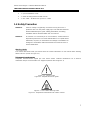
Warning Labels
The caution label means that you should check the certain information on user manual when working
with the device. (Shown in Figure 1.1)
Étiquettes d'avertissement
L'étiquette d'avertissement signifie que vous devez vérifier certaines informations sur le manuel
d'utilisation lorsque vous travaillez avec l'appareil. (Montré dans la figure 1.1)
Figure 1.1 - Caution Label
Figure 1.1 - Étiquette de mise en garde
Figure 1.2 - Hot Surface Warning Label
Figure 1.2 - Étiquette d'avertissement de surface chaude

Antaira Technologies - Industrial Ethernet Switches
LNX-1204G-10G-SFP Hardware Manual V1.0
8
2. Hardware Description
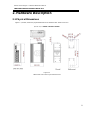
2.1 Physical Dimensions
Figure 2.1, below, shows the physical dimensions of Antaira’s LNX-1204G-10G-SFP:
(W x D x H) is 54mm x 99mm x 142mm
Figure 2.1
LNX-1204G-10G-SFP Physical Dimensions

Antaira Technologies - Industrial Ethernet Switches
LNX-1204G-10G-SFP Hardware Manual V1.0
9
2.2 Front Panel
The front panel of the LNX-1204G-10G-SFP industrial gigabit unmanaged Ethernet switch is
shown below in Figure 2.2.
Figure 2.2 - The Front Panel of LNX-1204G-10G-SFP
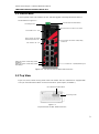
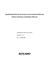
2.3 Top View
Figure 2.3, below, shows the top panel of the LNX-1204G-10G-SFP switch that is equipped with
one 6-pin removal terminal block connector for dual DC power inputs (12~48VDC).
Figure 2.3
Top Panel View of LNX-1204G-10G-SFP
LED for Power 1, Power 2, and Fault
6-Pin Removal Terminal Block
Grounding Screw
6-Pin Removal Terminal Block
Grounding Screw
SFP Port# 11~12 – 10G
SFP Port# 11~12 LED for
Link/Activity Status 10G
LAN# 1~8 – 10/100/1000Tx RJ45
LAN# 1~8 LED for Link/Activity Status
1000Mbps
LAN# 1~8 LED for Link/Activity Status
10/100Mbps
SFP Port# 9~10 LED for Link/Activity
Status 1G
SFP Port# 9~10 – 1G

Antaira Technologies - Industrial Ethernet Switches
LNX-1204G-10G-SFP Hardware Manual V1.0
10
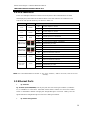
2.4 LED Indicators
There are LED light indicators located on the front panel of the industrial Ethernet switch
that display the power status and network status. Each LED indicator has a different color
and has its own specific meaning, see below in Table 2.1.
LED
Color
Description
P1
Green
On
Power input 1 is active
Off
Power input 1 is inactive
P2
Green
On
Power input 2 is active
Off
Power input 2 is inactive
Fault
Red
On
Power input 1 or 2 is inactive
Off
Power input 1 and 2 is active
LAN Port 1~8
(Upper LED)
Green
On
Connected to network, 1000Mbps
Flashing
Networking is active
Off
Not connected to network
LAN Port 1~8
(Lower LED)
Green
On
Connected to network, 10/100Mbps
Flashing
Networking is active
Off
Not connected to network
SFP Port 9~10
Green
On
Connected to network, 1000Mbps
Flashing
Networking is active
Off
Not connected to network
SFP+ Port
11~12
Green
On
Connected to network, 10Gbps
Flashing
Networking is active
Off
Not connected to network
Table 2.1 - LED Indicators for LNX-1204G-10G-SFP
Note: "P1" is the abbreviation for "Power 1", “P2” is for “Power 2”, “LNK” is for “Link”, and "ACT" is for
"Activity".
2.5 Ethernet Ports
•
RJ-45 Ports
RJ-45 Ports (Auto MDI/MDIX): The RJ-45 ports are auto-sensing for 10Base-T, 100Base-
TX, or 1000Base-T connections. Auto MDI means that the switch can connect to another
switch or workstation without changing the straight-through or crossover cabling. See the
figures below for straight-through and crossover cabling schematics.
•
RJ-45 Pin Assignments

Antaira Technologies - Industrial Ethernet Switches
LNX-1204G-10G-SFP Hardware Manual V1.0
11
Pin Number
Assignment
1
Rx+
2
Rx-
3
Tx+
6
Tx-
Table 2.3 - RJ45 Pin Assignments
Note: The “+” and “-” signs represent the polarity of the wires that make up each wire pair.
All ports on this industrial Ethernet switch support automatic MDI operations. Users can use
straight-through cables (see figure below) for all network connections to PCs, servers, and
other switches or hubs. With straight-through cabling, pins 1, 2, 3, and 6 are at one end of
the cable and are connected straight through to pins 1, 2, 3 and 6 at the other end of the
cable. The table below (Table 2.4) shows the 10BASE-T/100BASE-TX/1000BASE-T MDI
port pin outs.
Pin MDI-X
Signal Name
MDI Signal Name
1
Receive Data plus (RD+)
Transmit Data plus (TD+)
2
Receive Data minus (RD-)
Transmit Data minus (TD-)
3
Transmit Data plus (TD+)
Receive Data plus (RD+)
6
Transmit Data minus (TD-)
Receive Data minus (RD-)
Table 2.4 - Ethernet Signal Pin
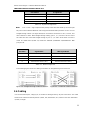
The following figures show the cabling schematics for straight-through and crossover.
2.6 Cabling
Use the four twisted-pair, category 5e, or the above cabling for the RJ-45 port connections. The cable
between the switch and the link partner (switch, hub, workstation, etc.) must be less than 100 meters
(328 ft.) in length.
Figure 2.4 - Straight-Through Cables Schematic Figure 2.5 - Crossover Cables Schematic

Antaira Technologies - Industrial Ethernet Switches
LNX-1204G-10G-SFP Hardware Manual V1.0
12
The small form-factor pluggable (SFP) is a compact optical transceiver used in optical communications for
both telecommunication and data communication applications.
Caution: Please employ optional optical transceiver (SFP/Fixed Fiber) that complies with IEC-60825-1
and classified as Class 1 laser product.
Attention: Veuillez utiliser un émetteur-récepteur optique en option (SFP/fibre fixe) conforme à la norme
IEC-60825-1 et classé comme produit laser de classe 1.
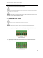
2.7 Wiring the Power Inputs
Caution: Please follow the steps below when inserting the power wire.
Attention: Veuillez suivre les étapes ci-dessous lors de l'insertion du câble d'alimentation.
1. Insert the positive and negative wires into the PWR1 (V1+, V1-) and PWR2 (V2+, V2-)
contacts on the terminal block connector as shown below in Figure 2.6.
2. Tighten the wire-clamp screws to prevent the wires from loosening, as shown below
in Figure 2.7.
Figure 2.7
Power Terminal Block
Figure 2.6
Power Terminal Block

Antaira Technologies - Industrial Ethernet Switches
LNX-1204G-10G-SFP Hardware Manual V1.0
13
Caution:
• Only use copper conductors, 125°C, tighten to 5 lbs.
• The wire gauge for the terminal block should range between 18~20 AWG.
Attention:
• Utilisez uniquement des conducteurs en cuivre, 125°C, serrez à 5 lb.
• Le calibre des fils du bornier doit être compris entre 18 et 20 AWG.
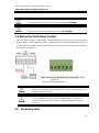
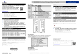
2.8 Wiring the Fault Alarm Contact
The fault alarm contact is in the middle of the terminal block connector as the picture shows
below in Figure 2.8. By inserting the wires, it will detect the fault status including power failure or
port link failure (managed industrial switch only) and form a normal open circuit. An example is
shown below in Figure 2.8.
Caution:
• The wire gauge for the terminal block should range between 12 ~ 24 AWG.
• If only using one power source, jumper Pin 1 to Pin 5 and Pin 2 to Pin 6 to
eliminate power fault alarm.
Attention:
• Le calibre des fils du bornier doit être compris entre 12 et 24 AWG.
• Si vous n'utilisez qu'une seule source d'alimentation, connectez les
broches 1 à 5 et les broches 2 à 6 pour éliminer l'alarme de panne de
courant.
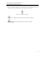
2.9 Grounding Note
Figure 2.8
Wiring the Fault Alarm Contact

Antaira Technologies - Industrial Ethernet Switches
LNX-1204G-10G-SFP Hardware Manual V1.0
14
Grounding and wire routing help limit the effects of noise due to Electromagnetic Interference
(EMI). Run the ground connection from the ground screw to the grounding surface prior to
connecting devices. The grounding screw symbol is shown blow in Figure 2.9.
Figure 2.9 - Grounding screw symbol
Caution: Using a shielded cable achieves better electromagnetic compatibility.
Attention: L'utilisation d'un câble blindé permet une meilleure compatibilité
électromagnétique.

Antaira Technologies - Industrial Ethernet Switches
LNX-1204G-10G-SFP Hardware Manual V1.0
15
3. Mounting Installation
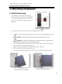
3.1 DIN-Rail Mounting
The DIN-Rail is pre-installed on the industrial
Ethernet switch from the factory. If the DIN-Rail is
not on the industrial Ethernet switch, please see
Figure 3.1 to learn how to install the DIN-Rail on
the switch.
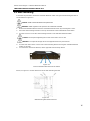
Follow the steps below to learn how to hang the industrial Ethernet switch.
1. Use the screws to install the DIN-Rail bracket on the rear side of the industrial Ethernet switch.
Caution: The torque for tightening the screws on the device is 3.5 in-lbs.
Attention: Le couple de serrage des vis sur l'appareil est de 3.5 pouces-livres.
2. To remove the DIN-Rail bracket, do the opposite from step 1.
3. After the DIN-Rail bracket is installed on the rear side of the switch, insert the top of the DIN-
Rail on to the track as shown below in Figure 3.2.
4. Lightly pull down the bracket on to the rail as shown below in Figure 3.3.
5. Check if the bracket is mounted tightly on the rail.
6.
To remove the industrial
Ethernet
switch from the rail, do the opposite from the above steps.
Figure 3.2
Insert the Switch on the DIN-Rail
Figure 3.3
Stable the Switch on DIN-Rail
Figure 3.1
The Rear Side of the Switch and DIN-Rail
Bracket

Antaira Technologies - Industrial Ethernet Switches
LNX-1204G-10G-SFP Hardware Manual V1.0
16
3.2 Wall Mounting
Follow the steps below to mount the industrial
Ethernet
switch using the wall mounting bracket as
shown below in Figure 3.4.
Caution: “Wall” means industrial control panel wall
Attention: “Wall” signifie mur de panneau de commande industriel
1. Remove the DIN-Rail bracket from the industrial Ethernet switch by loosening the screws.
2. Place the wall mounting brackets on the top and bottom of the industrial Ethernet switch.
3. Use the screws to screw the wall mounting bracket on the industrial Ethernet switch.
Caution: The torque for tightening the screws on the device is 3.5 in-lbs.
Attention: Le couple de serrage des vis sur l'appareil est de 3.5 pouces-livres.
4. Use the hook holes at the corners of the wall mounting bracket to hang the industrial Ethernet
switch on the wall.
5. To remove the wall mount bracket, do the opposite from the steps above.
Figure 3.4
Remove DIN-Rail Bracket from the Switch
Below, in Figure 3.5 are the dimensions of the wall mounting bracket.
Figure 3.5
Wall Mounting Bracket Dimensions

Antaira Technologies - Industrial Ethernet Switches
LNX-1204G-10G-SFP Hardware Manual V1.0
17
4. Hardware Installation
4.1 Installation Steps
This section will explain how to install Antaira’s LNX-1204G-10G-SFP:
Caution: This device is intended for use indoor.
Attention: Cet appareil est destiné à être utilisé à l'intérieur.
Caution: The device is intended to be installed in an industrial control enclosure and
panel.
Attention: L'appareil est destiné à être installé dans une armoire de commande et un
panneau industriels.
Installation Steps
1. Unpack the industrial Ethernet switch from the original packing box.
2. Check if the DIN-Rail bracket is screwed on the industrial Ethernet switch.
•
If the DIN-Rail is not screwed on the industrial Ethernet switch, please refer to the
DIN-Rail Mounting section for DIN-Rail installation.
•
If you want to wall mount the industrial Ethernet switch, please refer to the Wall
Mounting section for wall mounting installation.
3. To hang the industrial Ethernet switch on a DIN-Rail or wall, please refer to the Mounting
Installation section.
4. Power on the industrial Ethernet switch and then the power LED light will turn on.
•
If you need help on how to wire power, please refer to the Wiring the Power Inputs
section.
•
Please refer to the LED Indicators section for LED light indication.
5. Prepare the twisted-pair, straight-through category 5 cable for Ethernet connection.
6. Insert one side of the RJ-45 cable into switch’s Ethernet port and on the other side into the
networking device’s Ethernet port, e.g. switch PC or server. The Ethernet port’s (RJ-45) LED
on the industrial Ethernet switch will turn on when the cable is connected to the networking
device.
•
Please refer to the LED Indicators section for LED light indication.
7. When all connections are set and the LED lights all show normal, the installation is complete.

Antaira Technologies - Industrial Ethernet Switches
LNX-1204G-10G-SFP Hardware Manual V1.0
18
4.2 Maintenance and Service
•
If the device requires servicing of any kind, the user is required to disconnect and remove it from its
mounting. The initial installation should be done in a way that makes this as convenient as possible.
•
Voltage/Power lines should be properly insulated as well as other cables. Be careful when handling
them so as to not trip over.
•
Do not under any circumstance insert foreign objects of any kind into the heat dissipation holes
located in the different faces of the device. This may not only harm the internal layout, but might
cause harm to user as well.
•
Do not under any circumstance open the device for any reason. Please contact your dealer for any
repair needed or follow the instructions within the manual.
•
Clean the device with dry soft cloth.
4.3 Troubleshooting
•
Verify the right power cord/adapter, never use power supply/adapter with noncompliant DC output
voltage, or it will burn the equipment.
•
Select the proper UTP/STP cable to construct the network with using the right cable. Use unshielded
twisted-pair (UTP) or shield twisted-pair (STP) cable for RJ-45 connections: 100Ω Category 5e/above
cable for 10M/100Mbps. Also be sure that the length of any twisted-pair connection does not exceed 100
meters (328 feet).
•
Diagnosing LED Indicators: To assist in identifying problems, the Switch can be easily monitored through
LED indicators, which describe common problems a user may encounter and where the user can find
possible solutions.
•
If the power indicator LED does not turn on when the power cord is plugged in, the user may have a
problem with the power cord. Check for loose power connections, power losses or surges at the power
outlet. Please contact Antaira or Antaira’s authorized channel partners for technical support service, if the
problem still cannot be resolved.
•
If the Industrial switch LED indicators are normal and the connected cables are correct but the packets
still cannot transmit. Please check the system’s Ethernet devices’ configuration or status.

Antaira Technologies - Industrial Ethernet Switches
LNX-1204G-10G-SFP Hardware Manual V1.0
19
5.
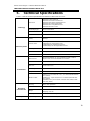
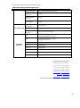
Technical Specifications
Table 5.1 has the technical specifications for Antaira’s LNX-1204G-10G-SFP:
Technology
Standards
IEEE 802.3 10Tx Ethernet
IEEE 802.3u 100Tx Fast Ethernet
IEEE 802.3ab 1000Tx Gigabit Ethernet
IEEE 802.3z 1000X Gigabit Fiber
IEEE 802.3ae 10 Gigabit Ethernet
IEEE 802.3x Flow Control
Processing Type
Store and Forward
Protocol
CSMA/CD
Flow Control
IEEE 802.3x flow control, back pressure flow control
Switch Properties
Back-Plane (Switching
Fabric)
60Gbps
Transfer Rate
14,880pps for Ethernet Port
148,800pps for Fast Ethernet Port
1,488,000pps for Gigabit Ethernet Port
14,880,000pps for 10 Gigabit Ethernet Port
Memory Buffer
8Mbits
Jumbo Frame
10Kbytes
MAC Table Size
16K
Port Interface
Ethernet Port
8*10/100/1000Base-TX, auto negotiation speed, Full/Half
duplex mode, and auto MDI/MDI-X connection
PoE Pin Out
V+, V+, V-, V-, for pin 1, 2, 3, 6 (End-span, Mode A)
SFP Port
2*1G SFP slots
2*10G SFP+ slots
Wavelength
Depends on SFP modules
Relay Contact
24VDC, 1A resistive
Network Cable
10Base-T: 2-pair UTP/STP Cat. 3, 4, 5 cable EIA/TIA-568 100-
ohm (100m)
100Base-TX: 2-pair UTP/STP Cat. 5 cable EIA/TIA-568 100-
ohm (100m)
1000Base-TX: 4-pair UTP/STP Cat.5/5E cable; EIA/TIA-568
100-ohm (100m)
Mechanical
Characteristics
Housing
Metal, IP30 protection
Dimensions
54 x 142 x 99 mm (W x H x D)
Weight
Unit: 2.35 lbs
Shipping: 2.97 lbs
Mounting
DIN-Rail, Wall-mounting
Power Requirement
Input Voltage
12~48VDC Redundant Input

Antaira Technologies - Industrial Ethernet Switches
LNX-1204G-10G-SFP Hardware Manual V1.0
20
Power Connection
1 removable 6-contact terminal block
Overload Current
Protection
Present
Reverse Polarity
Protection
Present
System Power
Consumption
11.3W
Environment Limits
Operating
Temperature
-40°C to 65°C
Storage Temperature
-40°C to 85°C
Ambient Relative
Humidity
5% to 95%, (non-condensing)
Regulatory
Approvals
EMI
FCC Part 15 Subpart B Class A,
CE EN55032/EN61000-6-4 Class A
EMS
CE EN55035/EN61000-6-2 Class A,
IEC61000-4-2,3,4,5,6,8
Free Fall
IEC60068-2-32
Shock
IEC60068-2-27
Vibration
IEC60068-2-6
Green
RoHS Compliant
Certifications
FCC, CE, UL 61010-1, 61010-2-201
Warranty
5 Years
Table 5.1 - LNX-1204G-10G-SFP Technical Specifications
Antaira Customer Service and Support
(Antaira US Headquarter) + 844-268-2472
(Antaira Europe Office) + 48-22-862-88-81
(Antaira Asia Office) + 886-2-2218-9733
Please report any problems to Antaira:
www.antaira.com / support@antaira.com
www.antaira.eu / info@antaira.eu
Any changes to this material will be announced on the Antaira website.
-
 1
1
-
 2
2
-
 3
3
-
 4
4
-
 5
5
-
 6
6
-
 7
7
-
 8
8
-
 9
9
-
 10
10
-
 11
11
-
 12
12
-
 13
13
-
 14
14
-
 15
15
-
 16
16
-
 17
17
-
 18
18
-
 19
19
-
 20
20


ANTAIRA LNX-1204G-10G-SFP Manuel utilisateur
- Catégorie
- Commutateurs réseau
- Taper
- Manuel utilisateur
- Ce manuel convient également à
dans d''autres langues
Documents connexes

Autres documents
-
 KYLAND Opal5G Guide d'installation
-
Yamaha SWR2311P-10G Le manuel du propriétaire
-
Leonton PG2-1002-SFP-24 Manuel utilisateur
-
Edimax 5/8 Manuel utilisateur
-
Edimax ES-3105P Manuel utilisateur
-
-
-
-
 EtherWAN EX61000A Series Quick Installation Guide
-

