
Publication 1756-IN611A-EN-P - February 2010
Installation Instructions
FactoryTalk Historian Machine Edition
Module
Catalog Number 1756-HIST1G and 1756-HIST2G
Use this document as a guide to install the FactoryTalk Historian Machine
Edition Module. Note that this document describes hardware installation
only. For configuration information, refer to the FactoryTalk Historian ME
User’s Guide, publication number 1756-UM611A-EN-E, available on the
FactoryTalk Historian ME Installation CD.
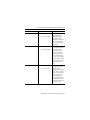
The following table lists the contents of this document and where to find
specific information.
Topic See Page
Important User Information 3
Environment and Enclosure Information 4
Prevent Electrostatic Discharge Information 4
Removal and Insertion Under Power (RIUP) Capability 5
North American Hazardous Location Approval 6
North American Hazardous Location Approval 7
Identify FactoryTalk Historian ME Module Components 9
Prepare the Chassis for Module Installation 11
Determine Module Slot Location 12
Install the Module in the Chassis 13
Remove or Replace the Module (when applicable) 14
Install or Remove the Module Under Power 15
Wire the Ethernet Connector 16

2 FactoryTalk Historian Machine Edition Module
Publication
1756-IN611A-EN-P - February 2010
Connect the Module to the Ethernet Network 16
Apply Chassis Power 17
Check Power Supply and Module Status 17
LED Indicator Information 18
Four-character LED Display 19
Application Status 21
Port (Ethernet) LED Information 23
Where to Find Information on Configuring the Module 23
How to Upgrade and Reinstall the Firmware 22
Specifications 24
Topic See Page

FactoryTalk Historian Machine Edition Module 3
Publication
1756-IN611A-EN-P - February 2010
I
Important User Information
Solid state equipment has operational characteristics differing from those of electromechanical
equipment. Safety Guidelines for the Application, Installation and Maintenance of Solid State
Controls (Publication SGI-1.1 available from your local Rockwell Automation sales office or
online at http://www.ab.com/manuals/gi) describes some important differences between solid
state equipment and hard-wired electromechanical devices. Because of this difference, and also
because of the wide variety of uses for solid state equipment, all persons responsible for
applying this equipment must satisfy themselves that each intended application of this
equipment is acceptable.
In no event will Rockwell Automation, Inc. be responsible or liable for indirect or
consequential damages resulting from the use or application of this equipment.
The examples and diagrams in this manual are included solely for illustrative purposes.
Because of the many variables and requirements associated with any particular installation,
Rockwell Automation, Inc. cannot assume responsibility or liability for actual use based on the
examples and diagrams.
No patent liability is assumed by Rockwell Automation, Inc. with respect to use of information,
circuits, equipment, or software described in this manual.
Reproduction of the contents of this manual, in whole or in part, without written permission of
Rockwell Automation, Inc. is prohibited.
Throughout this manual we use notes to make you aware of safety considerations when
necessary.
WARNING
Identifies information about practices or circumstances that can cause an
explosion in a hazardous environment, which may lead to personal injury or
death, property damage, or economic loss.
IMPORTANT
Identifies information that is critical for successful application and
understanding of the product.
Attention
Identifies information about practices or circumstances that can lead to personal
injury or death, property damage, or economic loss. Attentions help you:
• identify a hazard.
• avoid a hazard.
• recognize the consequence.
Shock Hazard
Labels may be located on or inside the equipment (e.g., drive or motor) to alert
people that dangerous voltage may be present.

4 FactoryTalk Historian Machine Edition Module
Publication
1756-IN611A-EN-P - February 2010
Environment and Enclosure Information
Burn Hazard
Labels may be located on or inside the equipment (e.g., drive or motor) to alert
people that surfaces may have dangerous temperatures.
Attention
This equipment is intended for use in a Pollution Degree 2 industrial
environment in overvoltage Category II applications (as defined in IEC
publication 60664-1) at altitudes up to 2000 meters without derating.
This equipment is considered Group 1, Class A industrial equipment according
to IEC/CISPR 11. Without appropriate precautions, there may be difficulties
with electromagnetic compatibility in residential and other environments due
to conducted and radiated disturbances.
This equipment is supplied as open-type equipment. It must be mounted within
an enclosure that is suitably designed for those specific environmental
conditions that will be present and appropriately designed to prevent personal
injury resulting from accessibility to live parts.The enclosure must have
suitable flame-retardant properties to prevent or minimize the spread of flame,
complying with a flame spread rating of 5VA, V2, V1, V0 (or equivalent) if
non-metallic. The interior of the enclosure must be accessible only by the use
of a tool. Subsequent sections of this publication may contain additional
information regarding specific enclosure type ratings that are required to
comply with certain product safety certifications.
NOTE: See NEMA Standards publication 250 and IEC publication 60529, as
applicable, for explanations of the degrees of protection provided by different
types of enclosure. Also, see the appropriate sections in this publication, as
well as the Allen-Bradley publication 1770-4.1 (“Industrial Automation Wiring
and Grounding Guidelines”), for additional installation requirements pertaining
to this equipment.
Important User Information

FactoryTalk Historian Machine Edition Module 5
Publication
1756-IN611A-EN-P - February 2010
Prevent Electrostatic Discharge Information
Attention
This equipment is sensitive to electrostatic discharge, which can cause internal
damage and affect normal operation. Follow these guidelines when you handle
this equipment:
• Touch a grounded object to discharge potential static.
• Wear an approved grounding wriststrap.
• Do not touch connectors or pins on component boards.
• Do not touch circuit components inside the equipment.
• Use a static-safe workstation, if available.
• Store the equipment in appropriate static-safe packaging when not in
use.

6 FactoryTalk Historian Machine Edition Module
Publication
1756-IN611A-EN-P - February 2010
Removal and Insertion Under Power (RIUP) Capability
Ethernet Network Communications Connections
North American Hazardous Location Approval
WARNING
When you insert or remove the module while backplane power is on, an electrical
arc can occur. This could cause an explosion in hazardous location installations. Be
sure that power is removed or the area is nonhazardous before proceeding. Repeated
electrical arcing causes excessive wear to contacts on both the module and its
mating connector. Worn contacts may create electrical resistance that can affect
module operation.
WARNING
If you connect or disconnect the communications cable with power applied to this
module or any device on the network, an electrical arc can occur. This could cause
an explosion in hazardous location installations. Be sure that power is removed or
the area is nonhazardous before proceeding.
The following information applies
when operating this equipment in
hazardous locations:
Informations sur l’utilisation de cet
équipement en environnements
dangereux:
Products marked “CL I, DIV 2, GP A,
B, C, D” are suitable for use in Class
I, Division 2 Groups A, B, C, D,
hazardous locations and
nonhazardous locations only. Each
product is supplied with markings on
the rating nameplate indicating the
hazardous location temperature code.
When combining products within a
system, the most adverse temperature
code (lowest “T” number) may be
used to help determine the overall
temperature code of the system.
Combinations of equipment in your
system are subject to investigation by
the local authority having jurisdiction
at the time of installation.
Les produits marqués “CL I, DIV 2, GP A,
B, C, D” ne conviennent qu’à une
utilisation en environnements de Classe I
Division 2 Groupes A, B, C, D dangereux
et non dangereux. Chaque produit est livré
avec des marquages sur sa plaque
d’identification qui indiquent le code de
température pour les environnements
dangereux. Lorsque plusieurs produits sont
combinés dans un système, le code de
température le plus défavorable (code de
température le plus faible) peut être utilisé
pour déterminer le code de température
global du système. Les combinaisons
d’équipements dans le système sont
sujettes à inspection par les autorités
locales qualifiées au moment de
l’installation.

FactoryTalk Historian Machine Edition Module 7
Publication
1756-IN611A-EN-P - February 2010
WARNING
EXPLOSION
HAZARD
• Do not disconnect
equipment unless
power has been
removed or the
area is known to
be nonhazardous.
• Do not disconnect
connections to
this equipment
unless power has
been removed or
the area is known
to be
nonhazardous.
Secure any
external
connections that
mate to this
equipment by
using screws,
sliding latches,
threaded
connectors, or
other means
provided with this
product.
• Substitution of
components may
impair suitability
for Class I,
Division 2.
• If this product
contains batteries,
they must only be
changed in an
area known to be
nonhazardous.
AVERTISSEMENT
RISQUE D’EXPLOSION
• Couper le courant
ou s’assurer que
l’environnement est
classé non
dangereux avant de
débrancher
l'équipement.
• Couper le courant
ou s'assurer que
l’environnement est
classé non
dangereux avant de
débrancher les
connecteurs. Fixer
tous les connecteurs
externes reliés à cet
équipement à l'aide
de vis, loquets
coulissants,
connecteurs filetés
ou autres moyens
fournis avec ce
produit.
• La substitution de
composants peut
rendre cet
équipement
inadapté à une
utilisation en
environnement de
Classe I, Division 2.
• S’assurer que
l’environnement est
classé non
dangereux avant de
changer les piles.
The following information applies
when operating this equipment in
hazardous locations:
Informations sur l’utilisation de cet
équipement en environnements
dangereux:

8 FactoryTalk Historian Machine Edition Module
Publication
1756-IN611A-EN-P - February 2010
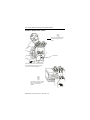
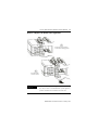
Identify FactoryTalk Historian ME Module Components
Use the following figures to identify the external features of the FactoryTalk
Historian ME Module.
FactoryTalk Historian ME Module Front View
In the following figure, the FactoryTalk Historian ME Module is shown from
the front view with the four-character LED display, LED indicators (BAT,
STS, OK), and Ethernet port locations identified.

FactoryTalk Historian Machine Edition Module 9
Publication
1756-IN611A-EN-P - February 2010
FactoryTalk Historian ME Module Side View
In the following figure, the FactoryTalk Historian ME Module is shown from
the side view with the backplane and compact flash card slot location
identified.
IMPORTANT
All data on the compact flash card is locked to Historian
ME modules. It cannot be read by any other device.

10 FactoryTalk Historian Machine Edition Module
Publication
1756-IN611A-EN-P - February 2010
Prepare the Chassis for Module Installation
Before you install the module, you must install and connect a ControlLogix
chassis and power supply.
For information on installing these products, refer to the publications listed
below.
Chassis
Type
Chassis
Installation
Power
Supply
Power
Supply
Installation
Series B: 1756-A4, -A7, -A10,
-A13, -A17
Pub. No.
1756-IN080
1756-PA72/B Pub. No.
1756-5.67
1756-PB72/B
1756-PA75/A Pub. No.
1756-5.78
1756-PB75/A
Power
Supply

FactoryTalk Historian Machine Edition Module 11
Publication
1756-IN611A-EN-P - February 2010
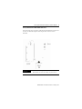
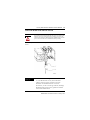
Determine Module Slot Location
You can install the module in any slot in the ControlLogix chassis. You can
have a maximum of two 1756-HIST modules in the same chassis. The figure
below shows chassis slot numbering in a 4-slot chassis. Slot 0 is the first slot
and is always the leftmost slot in the rack (the first slot to the right of the
power supply).
Slot 0
Slot 1
Slot 2
Slot 3
Chassis

12 FactoryTalk Historian Machine Edition Module
Publication
1756-IN611A-EN-P - February 2010
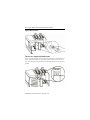
Install the Module in the Chassis
1
Slide the module into the chassis. Make sure
the module backplane connector properly
connects to the chassis backplane.
2
The module is properly installed
when it is flush with the power
supply or other installed
modules.
Circuit Board
3
Align the circuit board with the
top and bottom guides in the
chassis.

FactoryTalk Historian Machine Edition Module 13
Publication
1756-IN611A-EN-P - February 2010
Remove or Replace the Module (when applicable)
IMPORTANT
If you are replacing an existing module with an identical
one, and you want to resume identical system operation,
you must install the new module in the same slot.
Push on the upper and lower
module tabs to disengage them.
1
Slide the module
out of the chassis.
2

14 FactoryTalk Historian Machine Edition Module
Publication
1756-IN611A-EN-P - February 2010
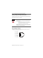
Install or Remove the Module Under Power
This module is designed to be installed or removed while chassis power is
applied. Rockwell Automation recommends that you stop all data collection
services before you remove the module.
Wire the Ethernet Connector
Use an RJ45 connector to connect to the Ethernet. Wire the connector
according to the following illustration:
WARNING
When you insert or remove a module while backplane power is on, an
electrical arc may occur. An electrical arc can cause personal injury or
property damage by:
• sending an erroneous signal to your system’s field device
causing unintended machine motion or loss of process control.
• causing an explosion in a hazardous environment.
Repeated electrical arcing causes excessive wear to contacts on both the
module and its mating connector. Worn contacts may create electrical
resistance that can affect module operation.
RJ 45
8
1
8 ------ NC
7 ------ NC
6 ------ RD-
5 ------ NC
4 ------ NC
3 ------ RD+
2 ------ TD-
1 ------ TD+

FactoryTalk Historian Machine Edition Module 15
Publication
1756-IN611A-EN-P - February 2010
Connect the Module to the Ethernet Network
Attach the RJ45 connector the Ethernet port on the front of the module as
shown.
WARNING
If you connect or disconnect the Ethernet cable with power applied to this
module or any device on the network, an electrical arc can occur. This
could cause an explosion in hazardous location installations. Be sure that
power is removed or the area is nonhazardous before proceeding.
IMPORTANT
We recommend connecting the module to the network
via a 100 MB Ethernet switch, which will reduce
collisions and lost packets and increase network
bandwidth. For detailed EtherNet connection
information, see the ControlLogic Ethernet/IP Bridge
Module Installation Instructions, publication number
1756-EN2T IN603B-EN-P.

16 FactoryTalk Historian Machine Edition Module
Publication
1756-IN611A-EN-P - February 2010
Apply Chassis Power
Check Power Supply and Module Status
Check the LED indicators and four-character LED display to determine if the
power supply and module are operating properly. Note that it can take up to
four to five minutes for the module to become fully operational once power is
applied.

FactoryTalk Historian Machine Edition Module 17
Publication
1756-IN611A-EN-P - February 2010
LED Indicator Information
There are two LED indicators on the front panel of the FactoryTalk Historian
ME Module: the three status LED lights and the four-character LED display.
These LED indicators determine if the power supply and module are
operating properly. They are described in the following sections.
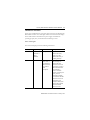
Status LED Lights
The Status LED lights provide the following information:
LED light On power-up Status Description
BAT Actual
indication of
battery
condition.
Battery status. Single red LED. Red
indicates the battery
charge is low. Off
indicates the battery is
operating normally.
STS Off Application
status. Refer to
the Application
Status section of
this guide for
status
descriptions.
Single bi-color red/green
LED. Flashing red
indicates that data
collection is active but
data transfer is inactive.
Solid red indicates that
data collection is
inactive. Check the
interface or scrolling text
display for more
information. Flashing
green indicates that data
collection is active but
data transfer is not
configured. Solid green
indicates that both data
collection and data
transfer are active.

18 FactoryTalk Historian Machine Edition Module
Publication
1756-IN611A-EN-P - February 2010
Four-character LED Display
The four-character LED display provides system status in a static and/or
scrolling string on the front panel of the FactoryTalk Historian ME Module.
Once an application is started, it has the responsibility of controlling this
display.
The four-character LED display provides the following information:
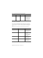
OK Green Module status. Single bi-color red/green
LED. Red indicates a
major fault has occurred
in the module. Green
indicates the module is
operating normally.
Process or component Four-character display Description
Start-up or re-set INIT Displays “INIT” for 3-5
seconds when initializing
start-up or re-set.
Start-up or re-set OK Displays “OK” for 3-5
seconds if the
initialization of all major
software components
was successful.
Shutting down SHUTTING DOWN Displays “SHUTTING
DOWN” during the
shutdown process.
Shut down SHUT DOWN Displays “SHUT
DOWN” when shut
down is finished.
LED light On power-up Status Description

FactoryTalk Historian Machine Edition Module 19
Publication
1756-IN611A-EN-P - February 2010
Ethernet port LAN OK Displays “LAN OK” if
the Ethernet port is
configured and the IP
address is acquired
properly, followed by the
IP address.
Ethernet port LAN LOST Displays “LAN LOST”
for several seconds if the
Ethernet port fails to
acquire the IP address.
After “LAN LOST”
appears, the MAC
address will be
displayed.
Application subsystems Configuration status: not
configured, no points.
Data Collection status:
collect ok, idle, collect
stopped.
Data Transfer status:
upload ok, upload
stopped, no upload.
Data Storage status:
storage critical, storage
full.
Refer to the Application
Status section of this
guide for detailed
information about the
application subsystems.
Process or component Four-character display Description

20 FactoryTalk Historian Machine Edition Module
Publication
1756-IN611A-EN-P - February 2010
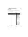
Application Status
The Application Status is composed of four application subsystems, as
described in the following table.
Note: If more than one of the four statuses exist, then they are displayed one
after another with a two second duration between each message.
Application Subsystem Status Description
Configuration status A. Not configured
B. No points
If neither Data Transfer
or Data Collection is
configured, then the “Not
configured” status is
displayed. Otherwise, the
status is empty. Note:
Data Collection is not
configured if the number
of subscribed points from
the data server is zero
(0). If Data Collection is
not configured, but Data
Transfer is configured,
then the configuration
status is “No points.”
Otherwise, the status is
empty. Note: Data
Transfer is not
configured if the SE Host
Server Name or IP
address is not entered or
is not resolved. The
status is “No upload.”
La page est en cours de chargement...
La page est en cours de chargement...
La page est en cours de chargement...
La page est en cours de chargement...
La page est en cours de chargement...
La page est en cours de chargement...
-
 1
1
-
 2
2
-
 3
3
-
 4
4
-
 5
5
-
 6
6
-
 7
7
-
 8
8
-
 9
9
-
 10
10
-
 11
11
-
 12
12
-
 13
13
-
 14
14
-
 15
15
-
 16
16
-
 17
17
-
 18
18
-
 19
19
-
 20
20
-
 21
21
-
 22
22
-
 23
23
-
 24
24
-
 25
25
-
 26
26


Rockwell Automation Allen-Bradley 1756-HIST2G Installation Instructions Manual
- Taper
- Installation Instructions Manual
- Ce manuel convient également à
dans d''autres langues
Documents connexes
Autres documents
-
 Allen-Bradley 1756-EN3TRK Guide d'installation
-
 Allen-Bradley ControlLogix 1756-PA75/B Installation Instructions Manual
-
 Allen-Bradley ControlLogix 1756-ENET/B Installation Instructions Manual
-
 Allen-Bradley 1756-PB72 Installation Instructions Manual
-
 Allen-Bradley ControlLogix 1756-EN2F Installation Instructions Manual
-
 Allen-Bradley ControlLogix 1756-IF4FXOF2F Installation Instructions Manual
-
 Allen-Bradley 2711P-RDT12H Installation Instructions Manual
-
Allen-Bradley 1756-PA75RK Installation Instructions Manual
-
 Allen-Bradley 1757-ABRIO Installation Instructions Manual
-
 Allen-Bradley ControlLogix 1756-IF6CIS Installation Instructions Manual


