Genius SKILL 01 Le manuel du propriétaire
- Catégorie
- Ouvre-porte
- Taper
- Le manuel du propriétaire

Skill 01

AVVERTENZE PER L’INSTALLATORE
OBBLIGHI GENERALI PER LA SICUREZZA
1) ATTENZIONE! È importante per la sicurezza delle persone seguire attenta-
mente tutta l’istruzione. Una errata installazione o un errato uso del prodotto
può portare a gravi danni alle persone.
2)
Leggere attentamente le istruzioni prima di iniziare l’installazione del prodot-
to.
3) I materiali dell’imballaggio (plastica, polistirolo, ecc.) non devono essere
lasciati alla portata dei bambini in quanto potenziali fonti di pericolo.
4) Conservare le istruzioni per riferimenti futuri.
5) Questo prodotto è stato progettato e costruito esclusivamente per l’utilizzo
indicato in questa documentazione. Qualsiasi altro utilizzo non espressamen-
te indicato potrebbe pregiudicare l’integrità del prodotto e/o rappresen-
tare fonte di pericolo.
6) GENIUS declina qualsiasi responsabilità derivata dall’uso improprio o diverso
da quello per cui l’automatismo è destinato.
7) Non installare l’apparecchio in atmosfera esplosiva: la presenza di gas o fumi
infiammabili costituisce un grave pericolo per la sicurezza.
8) Gli elementi costruttivi meccanici devono essere in accordo con quanto
stabilito dalle Norme EN 12604 e EN 12605.
Per i Paesi extra-CEE, oltre ai riferimenti normativi nazionali, per ottenere un
livello di sicurezza adeguato, devono essere seguite le Norme sopra riporta-
te.
9) GENIUS non è responsabile dell’inosservanza della Buona Tecnica nella co-
struzione delle chiusure da motorizzare, nonché delle deformazioni che
dovessero intervenire nell’utilizzo.
10) L’installazione deve essere effettuata nell’osservanza delle Norme EN 12453
e EN 12445. Il livello di sicurezza dell’automazione deve essere C+E.
11) Prima di effettuare qualsiasi intervento sull’impianto, togliere l’alimentazione
elettrica.
12) Prevedere sulla rete di alimentazione dell’automazione un interruttore
onnipolare con distanza d’apertura dei contatti uguale o superiore a 3 mm.
È consigliabile l’uso di un magnetotermico da 6A con interruzione onnipolare.
13) Verificare che a monte dell’impianto vi sia un interruttore differenziale con
soglia da 0,03 A.
14) Verificare che l’impianto di terra sia realizzato a regola d’arte e collegarvi
le parti metalliche della chiusura.
15) L’automazione dispone di una sicurezza intrinseca antischiacciamento co-
stituita da un controllo di coppia. E' comunque necessario verificarne la sogli
di intervento secondo quanto previsto dalle Norme indicate al punto 10.
16) I dispositivi di sicurezza (norma EN 12978) permettono di proteggere even-
tuali aree di pericolo da Rischi meccanici di movimento, come ad Es.
schiacciamento, convogliamento, cesoiamento.
17) Per ogni impianto è consigliato l’utilizzo di almeno una segnalazione lumino-
sa nonché di un cartello di segnalazione fissato adeguatamente sulla struttu-
ra dell’infisso, oltre ai dispositivi citati al punto “16”.
18) GENIUS declina ogni responsabilità ai fini della sicurezza e del buon funziona-
mento dell’automazione, in caso vengano utilizzati componenti dell’impian-
to non di produzione GENIUS.
19) Per la manutenzione utilizzare esclusivamente parti originali GENIUS.
20) Non eseguire alcuna modifica sui componenti facenti parte del sistema
d’automazione.
21) L’installatore deve fornire tutte le informazioni relative al funzionamento
manuale del sistema in caso di emergenza e consegnare all’Utente
utilizzatore dell’impianto il libretto d’avvertenze allegato al prodotto.
22) Non permettere ai bambini o persone di sostare nelle vicinanze del prodotto
durante il funzionamento.
23) Tenere fuori dalla portata dei bambini radiocomandi o qualsiasi altro datore
di impulso, per evitare che l’automazione possa essere azionata involonta-
riamente.
24) Il transito tra le ante deve avvenire solo a cancello completamente aperto.
25) L’Utente utilizzatore deve astenersi da qualsiasi tentativo di riparazione o
d’intervento diretto e rivolgersi solo a personale qualificato.
26) Tutto quello che non è previsto espressamente in queste istruzioni non è
permesso
CONSIGNES POUR L'INSTALLATEUR
RÈGLES DE SÉCURITÉ
1) ATTENTION! Il est important, pour la sécurité des personnes, de suivre à la
lettre toutes les instructions. Une installation erronée ou un usage erroné
du produit peut entraîner de graves conséquences pour les personnes.
2)
Lire attentivement les instructions avant d'installer le produit.
3) Les matériaux d'emballage (matière plastique, polystyrène, etc.) ne doivent
pas être laissés à la portée des enfants car ils constituent des sources
potentielles de danger.
4) Conserver les instructions pour les références futures.
5) Ce produit a été conçu et construit exclusivement pour l'usage indiqué dans
cette documentation. Toute autre utilisation non expressément indiquée
pourrait compromettre l'intégrité du produit et/ou représenter une source
de danger.
6) GENIUS décline toute responsabilité qui dériverait d'usage impropre ou
différent de celui auquel l'automatisme est destiné.
7) Ne pas installer l'appareil dans une atmosphère explosive: la présence de
gaz ou de fumées inflammables constitue un grave danger pour la sécurité.
8) Les composants mécaniques doivent répondre aux prescriptions des Normes
EN 12604 et EN 12605.
Pour les Pays extra-CEE, l'obtention d'un niveau de sécurité approprié exige
non seulement le respect des normes nationales, mais également le respect
des Normes susmentionnées.
9) GENIUS n'est pas responsable du non-respect de la Bonne Technique dans la
construction des fermetures à motoriser, ni des déformations qui pourraient
intervenir lors de l'utilisation.
10) L'installation doit être effectuée conformément aux Normes EN 12453 et EN
12445. Le niveau de sécurité de l'automatisme doit être C+E.
11) Couper l'alimentation électrique avant toute intervention sur l'installation.
12) Prévoir, sur le secteur d'alimentation de l'automatisme, un interrupteur
omnipolaire avec une distance d'ouverture des contacts égale ou supérieure
à 3 mm. On recommande d'utiliser un magnétothermique de 6A avec
interruption omnipolaire.
13) Vérifier qu'il y ait, en amont de l'installation, un interrupteur différentiel avec
un seuil de 0,03 A.
14) Vérifier que la mise à terre est réalisée selon les règles de l'art et y connecter
les pièces métalliques de la fermeture.
15) L'automatisme dispose d'une sécurité intrinsèque anti-écrasement, formée
d'un contrôle du couple. Il est toutefois nécessaire d'en vérifier le seuil
d'intervention suivant les prescriptions des Normes indiquées au point 10.
16) Les dispositifs de sécurité (norme EN 12978) permettent de protéger des
zones éventuellement dangereuses contre les Risques mécaniques du
mouvement, comme l'écrasement, l'acheminement, le cisaillement.
IMPORTANT NOTICE FOR THE INSTALLER
GENERAL SAFETY REGULATIONS
1) ATTENTION! To ensure the safety of people, it is important that you read
all the following instructions. Incorrect installation or incorrect use of the
product could cause serious harm to people.
2)
Carefully read the instructions before beginning to install the product.
3) Do not leave packing materials (plastic, polystyrene, etc.) within reach of
children as such materials are potential sources of danger.
4) Store these instructions for future reference.
5) This product was designed and built strictly for the use indicated in this
documentation. Any other use, not expressly indicated here, could compro-
mise the good condition/operation of the product and/or be a source of
danger.
6) GENIUS declines all liability caused by improper use or use other than that for
which the automated system was intended.
7) Do not install the equipment in an explosive atmosphere: the presence of
inflammable gas or fumes is a serious danger to safety.
8) The mechanical parts must conform to the provisions of Standards EN 12604
and EN 12605.
For non-EU countries, to obtain an adequate level of safety, the Standards
mentioned above must be observed, in addition to national legal regulations.
9) GENIUS is not responsible for failure to observe Good Technique in the
construction of the closing elements to be motorised, or for any deformation
that may occur during use.
10) The installation must conform to Standards EN 12453 and EN 12445. The safety
level of the automated system must be C+E.
11) Before attempting any job on the system, cut out electrical power.
12) The mains power supply of the automated system must be fitted with an all-
pole switch with contact opening distance of 3mm or greater. Use of a 6A
thermal breaker with all-pole circuit break is recommended.
13) Make sure that a differential switch with threshold of 0.03 A is fitted upstream
of the system.
14) Make sure that the earthing system is perfectly constructed, and connect
metal parts of the means of the closure to it.
15) The automated system is supplied with an intrinsic anti-crushing safety device
consisting of a torque control. Nevertheless, its tripping threshold must be
checked as specified in the Standards indicated at point 10.
16) The safety devices (EN 12978 standard) protect any danger areas against
mechanical movement Risks, such as crushing, dragging, and shearing.
17) Use of at least one indicator-light is recommended for every system, as well
as a warning sign adequately secured to the frame structure, in addition to
the devices mentioned at point “16”.
18) GENIUS declines all liability as concerns safety and efficient operation of the
automated system, if system components not produced by GENIUS are used.
19) For maintenance, strictly use original parts by GENIUS.
20) Do not in any way modify the components of the automated system.
21) The installer shall supply all information concerning manual operation of the
system in case of an emergency, and shall hand over to the user the warnings
handbook supplied with the product.
22) Do not allow children or adults to stay near the product while it is operating.
23) Keep remote controls or other pulse generators away from children, to
prevent the automated system from being activated involuntarily.
24) Transit through the leaves is allowed only when the gate is fully open.
25) The user must not attempt any kind of repair or direct action whatever and
contact qualified personnel only.
26) Anything not expressly specified in these instructions is not permitted.

6
ENGLISH
103
900
120
45
1
2
3
4
5
7
8
6
Fig. 1
Fig. 2
Fig. 3
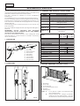
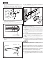
The SKILL automated system for swing gates is an electro-
mechanical operator transmitting motion to the leaf via a
planetary reduction and worm screw system.
The SKILL operator is suitable for every installation
requirement.
It is available both in non-reversing and reversing version.
The non-reversing version ensures the gate is mechanically
locked when the motor is not operating and, therefore, no
lock needs to be installed and is equipped with a manual
release with key.
The reversing version needs an electric lock to ensure the
lock of the leaf.
The "LS" models are equipped with opening and closing limit-
switches.
ATTENTION: Correct operation and declared
characteristics can be obtained only by using GENIUS
accessories and safety devices.
The SKILL automated systems were designed and
manufactured to control access of vehicles. Avoid any
other use whatever.
1. DESCRIPTION
2. DIMENSIONS
3. VERSIONS AND TECHNICAL SPECIFICATIONS
4. ELECTRIC EQUIPMENT (standard system)
LEDOM
LLIKS
RV-V
SLRV-SLV
RL-L
SLRL-SLL
ylppusrewoP zH)06(05caV032
rewopdebrosbA W052
tnerrucdebrosbA A50.1
rotomcirtcelE mpr0001
noitcetorplamrehT C°041
roticapaC Fµ3.6
tsurhT Nad081Nad002
levarT .mm503
deepS ces/mc4.1ces/mc2.1
fael.xaM m2m5.3
C°02ycneuqerfesU %03-3S
C°02selcycevitucesnoC 51
tneibmagnitarepO
erutarepmet
C°55+C°02-
ssalcnoitcetorP 44PI
thgiewrotarepO .gk4.8
snoisnemidrotarepO 2.gifees
LEDOMNOISREV
VLLIKS gnisrever-nondipar
LLLIKS gnisrever-nonwols
RVLLIKS gnisreverdipar
RLLLIKS gnisreverwols
SL-VLLIKS
dnagninepohtiwgnisrever-nondipar
hctiws-timilgnisolc
SL-LLLIKS
dnagninepohtiwgnisrever-nonwols
hctiws-timilgnisolc
SL-RVLLIKS
gnisolcdnagninepohtiwgnisreverdipar
hctiws-timil
SL-RLLLIKS
gnisolcdnagninepohtiwgnisreverwols
hctiws-timil
CAUTION: Front fitting
AUTOMATED SYSTEM SKILL
Dimensions in mm.
1) Motor unit
2) Manual release
3) Worm screw
4) Front fitting
5) Rear fitting
6) Power cable
7) Rear bracket
8) Front bracket
1) Operators
2) Photocells
3) Control board
4) Key-operated push-button
5) Receiver
6) Flashing lamp
Notes: 1) To lay electric cables, use adequate rigid
and/or flexible tubes.
2) Always separate low voltage accessories
cables from power cables at 230V ~. To avoid
any interference, always use separate sheaths.

7
ENGLISH
Fig. 4
Fig. A
Fig. B
B
A
Z
D
80min.
L
2
0
0
m
m
1
5
0
m
m
6
0
m
m
5. INSTALLATION OF THE AUTOMATED SYSTEM
5.1. PRELIMINARY CHECKS
To ensure trouble-free operation of the automated system,
make sure that the structure of the existing gate or the gate
to be installed, complies with the following requirements:
• max. single leaf length up to 2 metres (with V and VR
operator versions);
• max. single leaf length up to 3.5 metres (with L and LR
operator versions);
• sturdy and rigid leaf structure;
• proper and uniform movement of the leaves, without
any irregular friction during their entire travel;
• good condition of existing hinges;
• presence of mechanical stops.
• presence of the electric lock for the reversing version.
• presence of an efficient earthing for the electric
connection of the operator.
We advise you to carry out any metalwork jobs before
installing the automated system.
The condition of the structure directly affects the reliability
and safety of the automated system.
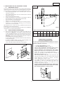
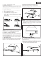
5.2. INSTALLATION OF THE OPERATORS
1) Secure the rear bracket on the pillar according to the
instructions of Dwg. A. If necessary, change the length
of the supplied bracket. Any securing errors may be
remedied thanks to 4 securing holes on the rear bracket.
Attention:
observe the indicated dimensions in order not
to endanger the operator efficiency.
In case of iron pillar, carefully weld the bracket directly
on the pillar (Fig. 4).
In case of masonry pillar, use the optional plate for a
securing to wall or to be bolted (Fig. 4).
Then carefully weld the bracket on the plate.
Table A: Recommended dimensions ( in mm.)
(¹) stem useful travel (²) max. dimension (³) min. dimension
GENERAL RULES TO DETERMINE
THE INSTALLATION DIMENSIONS
If the dimensions indicated in table A cannot be realized,
the following must be taken into consideration in order to
determine different measures:
- to get 90° leaf opening: a + b = c
- to get leaf opening over 90°: a + b < c
- lower a and b dimensions determine higher speed.
Current standards have to be complied with.
- limit the difference of the dimensions a and b within
4 cm: higher differences cause high speed variations
during the opening and closing movement.
- due to the operator overall dimensions, the min. Z
dimension is 80 mm (Fig. A).
- with the LS versions, dimensions A and B must be
used as they enable use of the entire travel. Shorter
travel distances could limit or reduce the limit-
switch adjustment range to zero.
- If the pillar dimensions or the hinge position make it
impossible to keep the dimensions a within the
desired measure, a niche on the pillar is to be
executed as shown in Fig. B.
- in the LS versions, the limit-switches are tripped only
during the first and last 25 mm of travel. As a result,
the full travel distance C must be used.
Skill
L-V-LR-VR
A B C (¹) D (²) Z (³) L
αα
αα
α
90°
110° 130
305
305
75
60
60
60
830
830
150150
130
Dwg. A INSTALLATION DIMENSIONS
Model

8
ENGLISH
Fig. 6
Fig. 7
Fig. 8
10
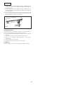
2) Secure the articulated fitting of the operator to the rear
bracket by means of the supplied pins (Fig. 5).
Attention: before securing the operator on the rear
bracket, which has just been welded, make sure its
temperature does not damage the articulated fitting.
3) Power up the motor and move the front attachment pin
backward by about 10 mm (fig. 6).
ATTENTION: The operator can be moved by hand only if
installed on the gate in released position.
4) Fit the front bracket to the front attachment pin as shown
in Fig. 7.
5) Close the gate leaf and, holding the operator in a
perfect horizontal position, locate the front bracket
securing point on the leaf (Fig. 8).
6) Temporarily secure the front bracket on the leaf by
means of two welding points.
Note: If the fitting cannot be secured firmly due to the
gate structure, a firm resting base on the structure is to
be created.
7) Release the operator and check manually if the gate is
free to open completely up to the mechanical stops and
if the leaf movement is regular and without any friction
whatever.
8) Completely weld the front bracket on the leaf (Fig. 8).
To do this, temporarily release the operator from the
fitting in order to avoid that welding slag damage it.
Note: We recommend to grease every fixing pin of the
fittings.
9) Carry out the installation of the second operator, if any,
repeating the above mentioned operations.
10) Install the enclosure and the control board keeping into
consideration the overall dimensions given in the relevant
instructions.
6. START-UP
ATTENTION: Before attempting any work on the system or on
the operator, always turn off power.
Observe points 10, 11, 12, 13, 14 of the GENERAL SAFETY
OBLIGATIONS.
Observing the instructions in Fig.3, lay the raceways and
make the electric connections of the control board to the
selected accessories.
Always separate power cables from control and safety
cables (push-button, receiver, photocells, etc...). To prevent
any electric noise whatever, use separate sheaths.
1) Program the control board according to your needs
observing the concerning instructions.
2) Switch on power to the system and check the condition
of the LEDs according to the table of the control board
instructions.
Fig. 5

9
ENGLISH
A
B
Fig. 9
Fig. 10
Fig. 11
3
1
4
2
Fig. 12
Fig. 13
7. TESTING THE AUTOMATED SYSTEM
Check operating efficiency of the automated system and all
accessories connected to it.
Hand the "User's Guide" page to the Client, explain correct
operation and use of the operator and indicate the
potentially dangerous areas of the automated system.
8. MANUAL OPERATION
If the gate has to be operated manually, turn off power and
proceed as follows:
1) Slide the protective tab, Fig.9 / 1.
2) Fit the key and turn it through 90°, Fig.9 / 2.
3) Lift up the manoeuvre lever, Fig.9 / 3.
4) To release the operator, turn the manoeuvre lever
through 180°, as shown by the arrow on the release
system Fig.9 / 4.
Open or close the leaves manually.
Attention: to keep the operator in manual operation mode,
the operator must be released and without power.
9. RESTORING NORMAL OPERATION
To restore normal operation mode of the automated system,
turn the metal lever clockwise, close the cover and switch
on power to the system.
Carry out some manoeuvres in order to check if all functions
of the automated system have been correctly restored.
10. MECHANICAL STOP
The SKILL operator is equipped with an opening mechanical
stop, Fig.10, which can be adjusted according to need.
Procedure for adjusting the stop position:
1) Release the operator as described in point 8.
2) Manually take the leaf into its opening position.
3) Loosen the fixing screw, Fig.11 ref. A. There is no need to
fully remove the screw.
4) Shift the stop to the lower support, as shown in fig. 12.
Attention: the mechanical stop operates coupled to a
sector gear, Fig. 11 ref. B, if anything occurs to impede
movement, make sure the coupling is unrestricted. Do
not force.
5) Re-tighten the fixing screw.
13.ADJUSTING THE LIMIT-SWITCHES
N.B.: The LS versions imply the use of equipment with an input
for the limit-switches.
The limit-switches are tripped only during the first and last 25
mm of travel. As result, the full travel distance must be used.
1) Remove the mechanical stop and the lower housing, in
the order described, as indicated in Fig. 13.

10
ENGLISH
Fig. 14
2) Loosen the two screws (Fig.14 ref. A), axially shift the
closing limit-switch to the required position and re-tighten
the two screws.
3) Loosen the two screws (Fig.14 ref. B), axially shift the
opening limit-switch to the required position and re-tighten
the two screws.
4) Run a couple of test cycles to check if the limit-switches
are correctly positioned. If the limit-switches have to be
adjusted again, resume from point 2.
5) Re-fit the lower housing.
12.MAINTENANCE
To ensure correct long-term operation, we advise you to
carry out the following checks every six months:
1) Check if all the safety devices in use are connected and
efficient.
2) Check if the anti-crushing clutch is correctly set.
3) Check the condition and efficiency of the earth
connection.
4) Check if all screws are tight.
5) Check wear and lubrication of the hinges.
13.REPAIRS
For any repairs, contact the authorised Repair Centres.

I0094 REV.2
GENIUS s.r.l.
Via Padre Elzi, 32
24050 - Grassobbio
BERGAMO-ITALY
tel. 0039.035.4242511
fax. 0039.035.4242600
www.geniusg.com
Timbro rivenditore: / Distributor’s stamp: / Timbre de l’agent: /
Sello del revendedor: / Fachhändlerstempel:
Le descrizioni e le illustrazioni del presente manuale non sono
impegnative. GENIUS si riserva il diritto, lasciando inalterate le
caratteristiche essenziali dell’apparecchiatura, di apportare in
qualunque momento e senza impegnarsi ad aggiornare la
presente pubblicazione, le modifiche che essa ritiene
convenienti per miglioramenti tecnici o per qualsiasi altra
esigenza di carattere costruttivo o commerciale.
The descriptions and illustrations contained in the present
manual are not binding. GENIUS reserves the right, whils leaving
the main features of the equipments unaltered, to undertake
any modifications to holds necessary for either technical or
commercial reasons, at any time and without revising the
present publication.
Les descriptions et les illustrations du présent manuel sont
fournies à titre indicatif. GENIUS se réserve le droit d’apporter à
tout moment les modifications qu’elle jugera utiles sur ce
produit tout en conservant les caractéristiques essentielles,
sans devoir pour autant mettre à jour cette publication .
Las descripciones y las ilustraciones de este manual no
comportan compromiso alguno. GENIUS se reserva el derecho,
dejando inmutadas las características esenciales de los
aparatos, de aportar, en cualquier momento y sin
comprometerse a poner al día la presente publicación, todas
las modificaciones que considere oportunas para el
perfeccionamiento técnico o para cualquier otro tipo de
exigencia de carácter constructivo o comercial.
Die Beschreibungen und Abbildungen in vorliegendem
Handbuch sind unverbindlich. GENIUS behält sich das Recht
vor, ohne die wesentlichen Eigenschaften dieses Gerätes zu
verändern und ohne Verbindlichkeiten in Bezung auf die
Neufassung der vorliegenden Anleitungen, technisch bzw,
konstruktiv / kommerziell bedingte Verbesserungen
vorzunehmen.
DICHIARAZIONE CE DI CONFORMITÁ PER MACCHINE
(DIRETTIVA 89/392 CEE, ALLEGATO II, PARTE B)
Fabbricante: GENIUS s.r.l.
Indirizzo: Via Padre Elzi, 32
24050 - Grassobbio
BERGAMO - ITALIA
Dichiara che: L'Attuatore mod. SKILL 01
• è costruito per essere incorporato in una macchina o
per essere assemblato con altri macchinari per
costituire una macchina ai sensi della Direttiva 89/
392 CEE, e successive modifiche 91/368/CEE, 93/44/
CEE, 93/68/CEE;
• è conforme ai requisiti essenziali di sicurezza
delle seguenti altre direttive CEE:
73/23 CEE e successiva modifica 93/68/CEE.
89/336 CEE e successiva modifica 92/31 CEE e
93/68/CEE
Grassobbio, 1 Marzo 2002
L’Amministratore Delegato
D. Gianantoni
EC MACHINE DIRECTIVE COMPLIANCE DECLARATION
(DIRECTIVE 89/392 EEC, APPENDIX II, PART B)
Manufacturer: GENIUS s.r.l.
Address: Via Padre Elzi, 32
24050 - Grassobbio
BERGAMO - ITALY
Hereby declares that: the SKILL 01
• is intended to be incorporated into machinery, or to
be assembled with other machinery to constitute
machinery in compliance with the requirements of
Directive 89/392 EEC, and subsequent amendments
91/368 EEC, 93/44 EEC and 93/68 EEC;
• complies with the essential safety requirements in the
following EEC Directives:
73/23 EEC and subsequent amendment 93/68 EEC.
89/336 EEC and subsequent amendments 92/31 EEC
and 93/68 EEC.
Grassobbio, 1 March 2002
Managing Director
D. Gianantoni
DÉCLARATION CE DE CONFORMITÉ
(DIRECTIVE EUROPÉENNE "MACHINES" 89/392/CEE,
ANNEXE II, PARTIE B)
Fabricant: GENIUS s.r.l.
Adresse: Via Padre Elzi, 32
24050 - Grassobbio
BERGAMO - ITALIE
Déclare d’une part que l'automatisme mod. SKILL 01
• est prévue soit pour être incorporée dans une machine,
soit pour être assemblée avec d’autres composants
ou parties en vue de former une machine selon la
directive européenne "machines" 89/392 CEE, modifiée
91/368 CEE, 93/44 CEE, 93/68 CEE.
• satisfait les exigences essentielles de sécurité des
directives CEE suivantes:
73/23 CEE, modifiÈe 93/68 CEE.
89/336 CEE, modifiÈe 92/31 CEE et 93/68 CEE.
et d’autre part qu’il est formellement interdit de mettre en
fonction l'automatisme en question avant que la machine
dans laquelle il sera intégrée ou dont il constituera un
composant ait été identifiée et déclarée conforme aux
exigences essentielles de la directive européenne "machines"
89/392/CEE, et décrets de transposition de la directive.
Grassobbio, le 1 Mars 2002
L’Administrateur Délégué
D. Gianantoni
DECLARACIÓN DE CONFORMIDAD CE PARA MÁQUINAS
(DIRECTIVA 89/392 CEE, ANEXO II, PARTE B)
Fabricante: GENIUS s.r.l.
Dirección: Via Padre Elzi, 32
24050 - Grassobbio
BERGAMO - ITALIA
Declara que: El equipo automático mod. SKILL 01
• Ha sido construido para ser incorporado en una
máquina, o para ser ensamblado con otros
mecanismos a fin de constituir una máquina con
arreglo a la Directiva 89/392 CEE y a sus sucesivas
modificaciones 91/368 CEE, 93/44 CEE y 93/68 CEE.
• Cumple los requisitos esenciales de seguridad
establecidos por las siguientes directivas CEE:
73/23 CEE y sucesiva modificación 93/68 CEE,
89/336 CEE y sucesivas modificaciones 92/31 CEE y
93/68 CEE.
Asimismo, declara que no está permitido poner en marcha el
equipo si la máquina en la cual será incorporado, o de la cual
se convertirá en un componente, no ha sido identificada o no
ha sido declarada su conformidad a lo establecido por la
Directiva 89/392 CEE y sus sucesivas modificaciones, y a la ley
que la incorpora en la legislación nacional.
Grassobbio, 1º de Marzo de 2002.
Administrador Delegado
D. Gianantoni
EG-KONFORMITÄTSERKLÄRUNG ZU MASCHINEN
(gemäß EG-Richtlinie 89/392/EWG, Anhang II, Teil B)
Hersteller: GENIUS s.r.l.
Adresse: Via Padre Elzi, 32
24050 - Grassobbio
BERGAMO - ITALIEN
erklärt hiermit, daß: der Antrieb Mod. SKILL 01
• zum Einbau in eine Maschine oder mit anderen
Maschinen zu einer Maschine im Sinne der Richtlinie
89/392 EWG und deren Änderungen 91/368 EWG,
93/44 EWG, 93/68 EWG vorgesehen ist.
• den wesentlichen Sicherheitsbestimmungen
folgender anderer EG-Richtlinien entspricht:
73/23 EWG und nachträgliche Änderung 93/68 EWG
89/336 EWG und nachträgliche Änderung 92/31 EWG
sowie 93/68 EWG
und erklärt außerdem, daß die Inbetriebnahme solange
untersagt ist, bis die Maschine, in welche diese Maschine
eingebaut wird oder von der sie ein Bestandteil ist, den
Bestimmungen der Richtlinie 89/392 EWG sowie deren
nachträglichen Änderungen entspricht.
Grassobbio, 1 März 2002
Der Geschäftsführer
D. Gianantoni
e inoltre dichiara che non è consentito mettere in servizio il
macchinario fino a che la macchina in cui sarà incorporata o
di cui diverrà componente sia stata identificata e ne sia stata
dichiarata la conformità alle condizioni della Direttiva 89/392/
CEE e successive modifiche trasposta nella legislazione
nazionale dal DPR n° 459 del 24 Luglio 1996.
and furthermore declares that unit must not be put into service
until the machinery into which it is incorporated or of which it
is a component has been identified and declared to be in
conformity with the provisions of Directive 89/392 ECC and
subsequent amendments enacted by the national
implementing legislation.
-
 1
1
-
 2
2
-
 3
3
-
 4
4
-
 5
5
-
 6
6
-
 7
7
-
 8
8


Genius SKILL 01 Le manuel du propriétaire
- Catégorie
- Ouvre-porte
- Taper
- Le manuel du propriétaire
dans d''autres langues
- italiano: Genius SKILL 01 Manuale del proprietario
- English: Genius SKILL 01 Owner's manual
Documents connexes
-
Genius SKILL 01 Mode d'emploi
-
-
-
-
-
-
-
-
-