ELICA ERS630S1 Guide d'installation
- Catégorie
- Hottes
- Taper
- Guide d'installation

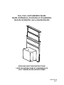
Use, Care, and Installation Guide
Guide d’utilisation, d’entretien et d’installation
Guía de instalación, uso y mantenimiento
READ AND SAVE THESE INSTRUCTIONS
LISEZ CES INSTRUCTIONS ET CONSERVEZ-LES
LEA Y GUARDE ESTAS INSTRUCCIONES
LIB0107214A
02/17

2
EN
FR
ES
Contents
Sommaire
Contenido
page
page
página
2
16
30
English
Contents
Important safety Notice................................................................................. 3
Electrical & Installation requirements ........................................................... 4
Before installing the hood ............................................................................. 4
List of Materials............................................................................................. 5
Parts supplied .............................................................................................. 5
Parts not supplied ........................................................................................ 5
Product Dimensions...................................................................................... 5
Countertop Cutout Dimensions................................................................... 6
Venting Requirements................................................................................... 6
Installation Instructions ................................................................................. 7
Determine which vent directioin is best for your installation ......................... 8
Rear mounting (reversible mode) ................................................................. 9
Complete Installation .................................................................................... 10
Control Installation ....................................................................................... 11
Electrical connection..................................................................................... 11
Check operation............................................................................................ 12
Downdraft use............................................................................................... 13
Vent system care........................................................................................... 13
Troubleshooting ............................................................................................ 14
Warranty ....................................................................................................... 15
APPROVED FOR RESIDENTIAL APPLIANCES
FOR RESIDENTIAL USE ONLY
READ AND SAVE THESE INSTRUCTIONS
PLEASE READ ENTIRE INSTRUCTIONS BEFORE
PROCEEDING.
INSTALLATION MUST COMPLY WITH ALL LOCAL CODES.
IMPORTANT: Save these Instructions for the Local
Electrical Inspector’s use.
INSTALLER: Please leave these Instructions with this unit
for the owner.
OWNER: Please retain these instructions for future
reference.
Safety Warning: Turn off power circuit at service panel and
lock out panel, before wiring this appliance.
Requirement: 120 V AC, 60 Hz. 15 or 20 A Branch Circuit

3
READ AND SAVE THESE INSTRUCTIONS
Important Safety Notice
CAUTION
FOR GENERAL VENTILATING USE ONLY. DO NOT USE TO
EXHAUST HAZARDOUS OR EXPLOSIVE MATERIALS OR
VAPOURS.
WARNING
TO REDUCE THE RISK OF FIRE, ELECTRIC SHOCK, OR INJURY
TO PERSONS, OBSERVE THE FOLLOWING:
A. Use this unit only in the manner intended by the manufacturer. If
you have questions, contact the manufacturer.
B. Before servicing or cleaning the unit, switch power off at service
panel and lock service panel disconnecting means to prevent
power from being switched on accidentally. When the service
disconnecting means cannot be locked, securely fasten a
prominent warning device, such as a tag, to the service panel.
C. Installation work and electrical wiring must be done by qualied
person(s) in accordance with all applicable codes & standards,
including re-rated construction.
D. Sufcient air is needed for proper combustion and exhausting of
gases through the ue (Chimney) of fuel burning equipment to
prevent back- drafting. Follow the heating equipment
manufacturers guideline and safety standards such as those
published by the National Fire Protection Association (NFPA), the
American Society for Heating, Refrigeration and Air Conditioning
Engineers (ASHRAE), and the local code authorities.
E. When cutting or drilling into wall or ceiling, do not damage
electrical wiring and other hidden utilities.
F. Ducted systems must always be vented to the outdoors.
CAUTION
To reduce risk of re and to properly exhaust air, be sure to duct
air outside - do not vent exhaust air into spaces within walls,
ceilings, attics, crawl spaces, or garages.
WARNING
TO REDUCE THE RISK OF FIRE, USE ONLY METAL DUCT WORK.
Install this hood in accordance with all requirements specied.
WARNING
To reduce the risk of re or electric shock, do not use this hood
with any external solid state speed control device.
WARNING
TO REDUCE THE RISK OF A RANGE TOP GREASE FIRE.
a) Never leave surface units unattended at high settings. Boilovers
cause smoking and greasy spillovers that may ignite. Heat oils
slowly on low or medium settings.
b) Always turn hood ON when cooking at high heat or when
ambeing food (i.E. Crepes suzette, cherries jubilee, peppercorn
beef ambe’).
c) Clean ventilating fans frequently. Grease should not be allowed to
accumulate on fan or lter.
d) Use proper pan size. Always use cookware appropriate for the
size of the surface element.
WARNING
TO REDUCE THE RISK OF INJURY TO PERSONS, IN THE EVENT
OF A RANGE TOP GREASE FIRE, OBSERVE THE FOLLOWING:
a
a) SMOTHER FLAMES with a close-tting lid, cookie sheet, or other
metal tray, then turn off the gas burner or the electric element. BE
CAREFUL TO PREVENT BURNS. If the ames do not go out
immediately, EVACUATE AND CALL THE FIRE DEPARTMENT.
b) NEVER PICK UP A FLAMING PAN - you may be burned.
c) DO NOT USE WATER, including wet dishcloths or towels - a
violent steam explosion will result.
d) Use an extinguisher ONLY if:
1) You know you have a class ABC extinguisher, and you already
know how to operate it.
2) The re is small and contained in the area where it started.
3) The re department is being called.
4) You can ght the re with your back to an exit.
a
Based on “Kitchen Fire Safety Tips” published by NFPA.
OPERATION
a. Always leave safety grills and lters in place. Without these com-
ponents, operating blowers could catch onto hair, ngers and loose
clothing.
The manufacturer declines all responsibility in the event of failure to
observe the instructions given here for installation, maintenance and
suitable use of the product. The manufacturer further declines all
responsibility for injury due to negligence and the warranty of the unit
automatically expires due to improper maintenance.

4
Electrical & Installation requirements
Electrical requirements
IMPORTANT
Observe all governing codes and ordinances.
Ensure that the electrical installation is adequate and in conformance
with National Electrical Code, ANSI/NFPA 70 (latest edition), or CSA
Standards C22.1-94, Canadian Electrical Code, Part 1 and C22.2 No.
0-M91 (latest edition) and all local codes and ordinances.
If codes permit and a separate ground wire is used, it is recom-
mended that a qualied electrician determine that the ground path is
adequate.
A copy of the above code standards can be obtained from:
National Fire Protection Association
One Batterymarch Park
Quincy, MA 02269
CSA International
8501 East Pleasant Valley Road
Cleveland, OH 44131-5575
• A 120 volt, 60 Hz., AC only, 15-amp, fused electrical circuit is
required.
• If the house has aluminum wiring, follow the procedure below:
1. Connect a section of solid copper wire to the pigtail leads.
2. Connect the aluminum wiring to the added section of copper wire
using special connectors and/or tools designed and UL listed for
joining copper to aluminum.
Follow the electrical connector manufacturer’s recommended
procedure. Aluminum/copper connection must conform with local
codes and industry accepted wiring practices.
• Wire sizes and connections must conform with the rating of the
appliance as specied on the model/serial rating plate. The model
serial plate is located on the front of the downdraft vent, above the
wiring box cover.
• Wire sizes must conform to the requirements of the National
Electrical Code, ANSI/NFPA 70 (latest edition), or CSA Standards
C22. 1-94, Canadian Electrical Code, Part 1 and C22.2 No. 0-M91
(latest edition) and all local codes and ordinances.
Before installing the hood
NOTE: Downdraft vent is installed directly behind the cooktop.
Install the downdraft vent rst, then install the cooktop.
IMPORTANT: Observe all governing codes and ordinances.
• Have a qualied technician install the downdraft vent. It is the
installer’s responsibility to comply with installation clearances
specied on the model/serial rating plate. The model/serial rating
plate is located on the front of the downdraft vent above the
terminal box cover.
• Downdraft vent location should be away from strong draft areas,
such as windows, doors, and strong heating vents or fans.
• Cabinet opening dimensions that are shown must be used. Given
dimensions provide minimum clearance.
• Consult the cooktop manufacturer installation instructions before
making any cutouts.
• Check that the downdraft vent and cooktop location will clear the
cabinet walls, backsplash, and rear wall studs inside the cabinet.
• Check for the minimum distance between the front edge of the
countertop and the front edge of the cooktop. The minimum
horizontal distance between the overhead cabinets is the same as
the width of the installed downdraft vent.
• All openings in ceiling and wall where the downdraft vent will be
installed must be sealed.
• Grounded electrical outlet is required. See “Electrical
Requirements” section.
• When installing the downdraft vent, the cabinet drawer will need to
be removed and the drawer front installed permanently to the
cabinet.
Cabinet Construction:
Downdraft vent is designed for use in a cabinet with a depth of
24” (61 cm). Some installations require a countertop deeper than
25” (63.5 cm). See the “Countertop Cutout Dimensions Chart.”
The maximum depth of the overhead cabinet is 13” (33 cm).
Overhead cabinets installed at either side of the downdraft vent
must be 18” (45.7 cm) above the cooking surface.
For Mobile Home Installations
The installation of this downdraft vent must conform to the
Manufactured Home Construction Safety Standards, Title 24
CFR, Part 328 (formerly the Federal Standard for Mobile Home
Construction and Safety, title 24, HUD, Part 280) or when such
standard is not applicable, the standard for Manufactured Home
Installation 1982 (Manufactured Home Sites, Communities and
Setups) ANSI A225.1/NFPA 501A, or latest edition, or with local
codes.

5
List of Materials
Removing the packaging
CAUTION!
Remove carton carefully, wear gloves to protect against sharp edges.
WARNING!
Remove the protective lm covering the product before putting into
operation.
Parts supplied
• Downdraft assembly with blower already installed
• Metal grease lters
• 2 - Lower support legs
• 2 - End caps
• 6” round air transition
• 3
1
⁄4”x10” rectangular air transition
• Metalic top trim
• Control assembly
• Hardware bag with:
• Use, care and installation guide
• Plastic control base
• 1 - Shrinkable wire tube
• 2 - Plastic wire ties
• 2 - Installation brackets
• 4 - Plastic clips for aspiration plate
• 7 - Adhesive wire clips
• 8 - 4 x 8 mm mounting screws
• 11 - 4.5 x 13 mm mounting screws
• 3 - 3.5 x 9.5 mm transition mounting screws
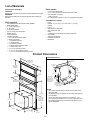
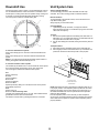
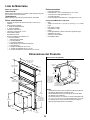
Product Dimensions
Parts needed
• Home power supply cable
• ½” (12.7 mm) UL listed or CSA approved strain relief
• 3 UL listed wire connectors
• 1 wall or roof cap
• 6” round metal vent system or 3
1
⁄4”x10” rectangular vent system
Tools/Materials required
• Level
• Drill with 1¼” (3.2 cm),⅛” (3.2 mm), and
5
⁄16” (7.9 mm)
drill bits
• Pencil
• Wire stripper or utility knife
• Tape measure or ruler
• Pliers
• Caulking gun and weatherproof caulking compound
• Vent clamps
• Jigsaw or keyhole saw
• Flat-blade screwdriver
• Metal snips
Top trim widths:
30” (76.2 cm)
36” (91.4 cm)
13
1
⁄2” (34.3 cm)
retractable
vent height
27” (68.6 cm) for 30” model
33” (83.8 cm) for 36” model
1
1
⁄2”
(3.8 cm)
28
1
⁄2”
(72.6 cm)
13
1
⁄8”
(33.4 cm)
16
1
⁄2”
(42 cm)
10”
(25.4 cm)
2
1
⁄8”
(5.4 cm)
5
1
⁄4” (13.3 cm)
for 30” models
8
1
⁄4” (21 cm)
for 36” models
19
⁄32”
(1.5 cm)
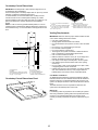
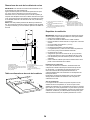
Cabinet Dimensions
9
1
⁄2”
(24.4 cm)
1
⁄2” (1.27 cm)
minimum
Centerline of
cooktop cutout
Locate power supply
junction box at lower
left hand rear corner
of the cabinet.
Cutouts are
for 3
1
⁄4” x 10”
(8.3 x 25.4 cm)
rectangular or 6”
(15.2 cm) round
vent system.
21
5
⁄16”
(54.1 cm)
21
5
⁄16”
(54.1 cm)
NOTES:
• See cooktop manufacturer’s instructions for cooktop cutout
depth and width.
• Use dimensions for vent system cutout location that applies to
your installation.
• Interior mounted blower systems connect with 3
1
⁄4” x 10”
(8.3 x 25.4 cm) rectangular or 6” (15.2 cm) round vent system.
The cutout locations for this vent system will depend on your
specic installation.

6
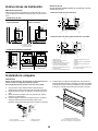
Countertop Cutout Dimensions
IMPORTANT: Countertops with a bull-nosed front edge are not rec-
ommended for these installations.
Some models require a countertop deeper than 25” (63.5 cm); see the
following “Countertop Cutout Dimensions Chart.”
To avoid mistakes, it is recommended that the cooktop and vent
cutouts be drawn on the countertop before making any cutouts.
See the Installation Instructions that came with your cooktop for com-
plete cutout dimensions, location dimensions and installation
details.
NOTE: In order to avoid any possible whistle problem, it is recom-
mended to keep at minimum the distance between the cooktop and
the downdraft vent (I). It is recommended a sealer application in that
area.
D
E
B
C
F
G
H
A
I
A. Downdraft vent
B. Cooktop
C.Measurement of cooktop rear overhang
D. D = Measurement of cooktop rear over-
hang (C) + 2
1
⁄2” [61 mm] (E)
E. 2
1
⁄2” (61 mm)
F.¼” (6.4 mm) minimum
G. Countertop and backsplash
H. ½” (12.7 mm) minimum
I. Seal the cooktop / downdraft joint
Countertop Cutout Dimensions Chart
A
B
D
F
G
C
E
A. ½” (12.7 mm) minimum to backsplash or
rear wall
B.
3
⁄4” (19.1 mm) maximum backsplash depth
C. 27½” (69.9 cm) on 30” (76.2 cm) models
33½” (85.9 cm) on 36” (91.4 cm) models
D. D = E+ 2
1
⁄2” (61 mm)
E. Cooktop rear overhang
F. Ø 2
9
⁄16” (6.5 cm). The control can be
installed in both left or right sides.
G. Minimum distance from cooktop 4” (10 cm)
maximum distance from cooktop 8” (20 cm)
Venting Requirements
IMPORTANT: Make sure there is proper clearance within the wall
or oor before making exhaust vent cutouts.
• Use heavy (rigid) metal vent.
• Venting system must terminate to the outside.
• Do not terminate the vent system in an attic or other enclosed
area.
• Do not use 4” (10.2 cm) laundry-type wall caps.
• Do not install 2 elbows together.
• Do not use plastic or metal foil vent.
• The length of vent system and number of elbows should be
kept to a minimum to provide efcient performance.
• Use no more than three 90° elbows
• Make sure there is a minimum of 24” (61 cm) of straight vent
between the elbows if more than one elbow is used.
• Use clamps or duct tape to seal all joints in the vent system.
• Use caulking tape to seal the exterior wall or oor opening
around cap.
• Do not cut joist or stud. If vent cutout falls over a joist or stud,
a supporting frame must be constructed.
• Flexible metal vent is not recommended. If it is used, calculate
each foot of exible vent as 2 ft (0.6 m) of rigid metal vent.
Flexible elbows count twice as much as standard elbows.
Cold Weather Installations
An additional back draft damper should be installed to minimize
backward cold air ow and a thermal break should be installed to
minimize conduction of outside temperatures as part of the vent
system. The damper should be on the cold air side of the thermal
break.
The break should be as close as possible to where the vent
system enters the heated portion of the house.
Makeup Air
Local building codes may require the use of makeup air systems
when using ventilation systems greater than specied CFM of air
movement. The specied CFM varies from locale to locale.
Consult your HVAC professional for specic requirements in your
area.

7
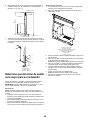
Installation Instructions
Venting Methods
Determine which venting method is best for your application.
Vent system can terminate either through the wall or oor.
Island locations
Front (standard) mounted
blower motor
Rear mounted blower motor
(Reversible version)
C
B
A
C
B
A
A. Down vent
B. Cooktop
C. Aspiration plate
Built-in cabinet locations
A
B
C
A. Down vent B. Left vent C. Right vent
Island locations
Vent systems installed under a concrete slab using PVC sewer
pipe.
Front (standard) mounted blower motor
B
CM
A
L
K J I
H
G
E
F
D
Rear mounted blower motor (reversible aspiration plate)
B
D
E
F
G
H
IJK
A
M C
L
A. Wall cap
B. 6” (15.2 cm) round metal vent
C.16” (40.6 cm) maximum
D. 6” (15.2 cm) round PVC swer pipe
E. 6” (15.2 cm) round metal vent transi-
tion with damper (supplied)
F. 6” (15.2 cm) round PVC coupling
G. Concrete slab
H. 6” (15.2 cm) round PVC sewer pipe
I. 6” (15.2 cm) round 90º PVC sewer
pipe elbow
J. Tightly pack gravel or sand
completely around pipe
K. 6” (15.2 cm) round 90º PVC sewer
pipe elbow
L. 6” (15.2 cm) round PVC coupling
M. 12” (30.5 cm) minimum
Installing the vent system
WARNING
Excessive Weight Hazard
Use two or more people to move and install downdraft vent.
Failure to do so can result in back or other injury.
1. Place cardboard or similar material on top of a at surface where
you can easily assemble the downdraft vent system.
2. Remove parts packages, downdraft vent and blower box from the
carton.
3. Remove all shipping materials, tape and lm from the downdraft
vent and blower box.
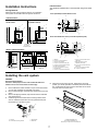
4. Install the right and left undercounter mounting brackets to the
vent box. Slide the keyhole slots over the guide tabs and push
the brackets up to set them in place.
A
B
C
D
A. Vent box
B. Undercounter mounting bracket
C. Keyhole slots
D. Guide tabs
5. Attach the end cap to the vent box, depending on what vent
position you choose (standard or reversible). Place the tabs into
the mounting slots at each end of the downdraft vent as shown
and push down to lock into place.
A
B
A. Standard installation cap
B. Reversible installation cap
NOTE: Only one cap must be mounted A or B

8
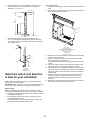
6. Measure distance “X” from the cabinet oor to the top of the
countertop. Subtract 28
1
⁄2” from distance “X” to determine
dimension “Y” (X - 28
1
⁄2 = Y).
Top of countertop
“X”
“Y”
Cabinet oor
28
1
⁄2”
(73 cm)
Downdraft
vent
7. Attach the support legs to the side of the vent box with
4 - 4 x 8 mm screws in each support leg. Adjust to dimension
“Y” from the bottom of the vent box to the bottom of the support
legs. Tighten screws.
A
C
B
dim. “Y”
A. Motor box
B. Support leg
C. Installation screws
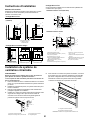
Determine which vent direction
is best for your installation
When installed in a cabinet, vent system can exhaust through the
bottom, right or left of the cabinet.
IMPORTANT: When using the 6” (15.2 cm) vent transition (supplied)
for 6” round venting, only left or right venting is recommended.
Bottom venting
NOTE: If installing the vent damper in the down position, a wall or
roof cap with a damper at the exit end of the vent system is required.
• Downdraft vent is shipped with blower in down venting position so
no modication is required.
• If rear mounting of the blower motor is not required, go to the
“Complete Installation” section.
• To mount the blower motor to the rear side of the vent box, go to
the “Rear Mounting (reversible mode)” section.
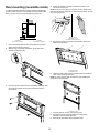
Left or right venting:
1. Using two or more people, place the downdraft vent system on its
back.
2. Remove the 4 screws from the cover plate mounted to the face of
the motor box and set them aside.
B
A
D
E
F
G
C
A.Cover plate
B. Cover plate screws
C. Cover plate keyhole slot shoulder screws
D.Motor mounting screws
E. Vent cover plate
F. Motor box
G. Vent cover screws
3. Slide the cover plate up and slip it over the keyhole slot shoulder
screws. Set the cover aside.
4. Remove 4 screws from the bottom of the motor box that hold
the motor assembly to the motor box.
NOTE: Disconnect the electrical wiring connection from motor if
needed.
5. Remove 3 screws and the vent cover plate from the left or right
side of the motor box for the venting direction to be used.
6. Rotate the blower motor assembly 90 degrees to the left or right
side to the chosen venting direction and secure to the blower box
with motor mounting screws previously removed. Do not twist or
bind the wires.
7. Install the vent cover plate over the rectangular opening in the
bottom of the motor box and secure with vent cover screws.
NOTE: Reinstall the electrical wiring connection to motor if
removed.
8. Reinstall the cover plate to the face of the motor box and secure
with 4 cover plate screws previously removed.

9
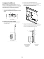
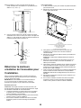
Rear mounting (reversible mode)
An optional aspiration assembly mounting position (opposite side)
for island cabinet locations. The aspiration assembly (metalic plate,
lters), can be moved to the opposite side (rear) of the vent.
A
B
C
D
A. Motor box
B. Aspiration orientation
C. Cooktop
D. Ensamble de aspiración
1. Move the aspiration plate and the grease lters and put them
aside. (See the Cleaning section).
2. With the help of a at head screwdriver, gently take off the
aspiration plate plastic clips.
3. Once the clips were removed from the aspration assembly, retire
the screws and washer as shown the image below. Put the
screws aside.
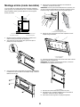
4. Unplug the aspiration assembly’s electrical connection, and
remove it from the hood.
NOTE: Once you have unplug the connector, cover it with the shrink-
able wire tube and the plastic ties as shows the image below. Set free
the opposite connector.
A
B
C
A.Plastic wire clip
B. Shrinkable wire tube
C. Aspiration assembly connection
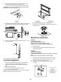
5. Remove the mounting screws from the aspiration structure as
shown the image below.
B
A
A. Aspiration structure
B. Installation screws
6. Lift the structure and ip it to the opposite side and x it with the
same screws previously removed.
NOTE: In order to properly align the structure, begin installing the
screws shown in the drawing.
A
A. Installation screws
7. Plug the electrical conexion and put it into place.
8. Put back the screws and metal washers to the aspiration
assembly. Insert the plastic clips back.
9. Relocate the grase lters and the aspiration plate.

10
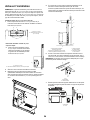
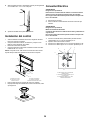
Complete Installation
NOTE: The downdraft vent system is supplied with a 3
1
⁄4” x 10”
(8.3 x 25.4 cm) rectangular vent transition and a 6” (15.2 cm) round
vent transition with damper. Refer to “3
1
⁄4” x 10” (8.3 x 25.4 cm) back
draft damper” or “6” (15.2 cm) round vent transition with
damper,” depending upon the type of venting you are using.
3
1
⁄4” x 10” (8.3 x 25.4 cm) back draft damper
1. Attach the 3¼” x 10” (8.3 x 25.4 cm) back draft damper to the
vent opening in the blower motor box, using three 3.5 x 9.5 mm
screws.
A
AB
A. 3.5 x 9.5 mm screws
B. 3¼” x 10” (8.3 x 25.4 cm) back draft damper
6” (15.2 cm) round vent transition with damper
2. Attach the 6” (15.2 cm) round vent transition to vent opening
(left or right side venting only is recommended), using two
3.5 x 9.5 mm screws.
A
B
A. 3.5 x 9.5 mm screws
B. 6” (15.2 cm) round vent transition with damper
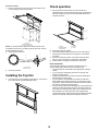
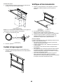
3. Remove 4 screws attaching the terminal box cover.
4. Determine which direction (front or rear) the home power supply
cable will enter the terminal box. Remove the appropriate
knockout from the front or rear panel and install a ½” (12.7 mm)
UL listed or CSA approved conduit connector.
5. Using 2 or more people, insert the downdraft vent into the
countertop cutout. Position downdraft vent so it is centered in the
cutout with the rear ange over the edge of the cutout and the
rear of the vent box against the edge of the cutout.
A
B
G
C
D
E
F
A. Rear ange of downdraft vent
B. Edge of cutout in countertop
C. Rear of downdraft vent
D. Cabinet back
E. Lower support leg
F. Cabinet oor
G. Countertop

11
6. Drill 2 pilot holes through each of the undercounter mounting
brackets into the underside of the countertop. Using
2 - 4.5 x 13 mm screws, mount the brackets to the countertop.
IMPORTANT: Select a screw length that will not allow the screws to
go through the countertop when tightened.
A
B
C
A. Screws
B. Backsplash
C. Countertop
7. Check that the downdraft vent is level vertically. Loosen the lower
support legs screws and position the legs against the cabinet
oor.
A
B
A
B
A. Downdraft
B. Level
9. Fasten the lower support legs to the cabinet oor with 2 - 4.5 x 13
screws (on each leg).
10. Tighten the lower support legs screws.
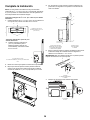
Control Installation
• Before the control installation, make sure you have made the
cutouts to proceed (see “Countertop Dimensions Chart”).
• Place the control base on location and mark the holes with a
pencil.
• Drill on the marked locations.
• Place the control base on the countertop and drive
3 - 4.5 x 13 mm installation screws.
NOTE: The legend “Front” is writen on the control base. This legend
always must be oriented to the hood’s front (F).
A
B
C
D
E
F
A. Countertop
B. Control cutout
C. Control base
D. Mounting screws
E. Hood’s front
F. Control base installation
• Run the control cable through the countertop hole.
• Push down the control assembly against the control base, until
you hear the click.
Electrical connection
WARNING
Electrical Shock Hazard
Disconnect power before servicing.
Replace all parts and panels before operating.
Failure to do so can result in death or electrical shock.
1. Disconnect power.
2. Feed the power supply cable through the conduit connector
and into the terminal box.
WARNING
Electrical Shock Hazard
Electrically ground blower.
Connect ground wire to green and yellow ground wire in terminal
box.
Failure to do so can result in death or electrical shock.
3. Connect the green (or green/yellow) ground wire to the green
or yellow/green ground wire using UL listed wire connectors.
4. Tighten the screw on the conduit connector.
5. Connect the 2 white wires together using UL listed wire
connectors.
A
D
B
F
C
E
A. Green or green and yellow
ground wire
B.White wires
C. UL listed wire connectors
D. Black wires
E. UL listed or CSA approved
conduit connector
F. Downdraft vent wiring

12
Control connection
1. Run the control wire from the motor box to the location of the
control assembly (see the image below).
A
B
C
A. Control
B. Adhesive wire clips
C. Control connection wire
NOTE: It is recommended to guide the connection wire as close
as posible to the motor box, avoiding to get the wire loose. Use the
provided adhesive wire clips.
2. Plug both wire connectors.
A
B
A. Control wire
B. Motor box wire
3. Check the operation.
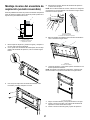
Installing the Top trim
1. Push down the top trim against the downdraft top. The top trim’s
pins must enter into the downdraft plastic clips.
Check operation
1. Push and hold the control button for a few seconds. The
retractable section of the downdraft vent will rise, and the blower
will start. Position the top trim over the retractable section and
snap trim into place.
A
B
C
D
E
A. Top trim
B. Aspiration plate
C. Grease lters
D. End cap
E. Control
2. If the blower does not operate:
• Check that aspiration plate is pressed in as far as they will go.
• Check that the circuit breaker has not tripped or a household
fuse blown.
3. Connect vent system to blower. Vent system must end with a
wall or roof cap. Use clamps or duct tape to seal all joints.
4. Install cooktop according to manufacturer’s instructions.
VENT SYSTEM USE
The retractable downdraft vent system is designed to remove
smoke, cooking vapors and odors from the cooktop area.
• For best results, the vent should be operating before cooking is
started.
• If you use large or tall utensils, place them on the large rear
element or burner surface.
• A higher heat setting than normally used may be needed when
the downdraft vent is operating.
• For gas cooktops, the downdraft vent system may affect the
ame stability and cooking performance. To improve the burner
performance, either decrease the downdraft vent blower speed or
increase the cooktop burner ame setting.
• For gas cooktops with ame sensing ignitions, the downdraft vent
system may disperse the ame away from the spark igniter and
may cause it to continually spark while trying to reignite a burner
that is already lit. To resolve the issue of the cooktop igniter
continuously sparking, either decrease the downdraft vent blower
speed or increase the cooktop ame setting for that burner.

13
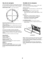
Downdraft Use
Use the high suction speed in cases of concentrated kitchen vapours.
It is recommended that the cooker hood suction is switched on for 5
minutes prior to cooking and to leave in operation during cooking and
for another 15 minutes approximately after terminating cooking.
The control panel consists of a backlit rotating disk.
A
B
C
D
E
To raise the downdraft vent system:
Press on the disk (E) aprox 2 seconds to raise the downdraft vent
system.
Press on the disk (E) aprox 2 seconds to hide the downdraft vent
system.
NOTE: If you press the disk to hide the downdraft system while it is
working, the appliance will automatically turn off.
To select the available suction speeds:
Turn the disk (E) clockwise to turn on and increase the suction speed
and counter-clockwise to decrease it, and to turn off the hood.
The crown lights to indicate the selected suction speed:
A lit
speed 1 (minimum).
A + B lit
speed 2 (medium).
A + B + C lit
Speed 3 (maximum).
A + B + C + D lit
Speed 4 (intensive), lasting for 5 minutes, then the hood is placed
automatically at speed 2.
A off:
Suction motor off.
A + B + C + D lit in ashing mode
The light crown will ash after 40 hrs. of work. This indicates that the
grease lters must be removed and cleaned.
This function must be reset by pressing the button for 5 seconds.
Vent System Care
Surface of Downdraft Vent
To avoid damaging the nish, clean downdraft vent with soap
and water. Do not use scouring powder or abrasive solutions.
Exterior Surfaces:
To avoid damage to the exterior surface, do not use steel wool or
soap-lled scouring pads.
Always wipe dry to avoid water marks.
Cleaning Method:
• Liquid detergent soap and water, or all-purpose cleanser
Wipe with damp soft cloth or nonabrasive sponge, then rinse with
clean water and wipe dry.
To Clean:
1. Remove the aspiration plate and the lter(s) and clean them in a
dishwasher or in a hot detergent solution. The downdraft vent will
not operate when the lters are not in place.
2. Dry the clean lter(s) and reinstall, making sure that they lock into
place.
To Replace Filters:
1. Place lters into the retractable section of the downdraft vent.
2. Place ngertips into the embossment at the top of the lters and
push down and back to allow the top tabs to snap in place.
A
B
C
A. Aspiration plate
B. Grease lter handle
B. Grease lters
NOTE: Downdraft vent will not operate if the aspiration plate are not
in its proper position. If the aspiration plates’ top tabs are not locked
behind the top ange, the vent may retract but not raise back up. If
retractable downdraft vent does not operate after clean aspiration
plate have been installed:
Push the aspiration plate in as far as it will go. When the plate is
removed, the microswitch behind the lter is inactivated. This feature
will not allow the vent system to operate until the aspiration plate is
properly installed.

14
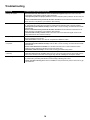
Troubleshooting
PROBLEM POSSIBLE CAUSES AND/OR SOLUTIONS
Nothing will operate Has a household fuse been blown or has a circuit breaker tripped? Replace the fuse or reset the
circuit breaker. If the problem continues, call an electrician.
Is the aspiration plate in its proper position? Check that aspiration plate is pressed in as far as they will
go.
Has the Control button been pressed for at least 2 seconds? Push and hold the control button for at
least 2 seconds to complete the cycle needed to start retracting.
Vent does not retract Is the aspiration plate in place? When the plate is removed, the microswitch behind the lter is inactivat-
ed. This feature will not allow the vent system to operate until the aspiration plate is properly installed.
Is the aspiration plate installed correctly? Push the lter in as far as it will go to activate the microswitch
behind the lter.
Has the Control button been pressed for at least 2 seconds? Push and hold the control button for at
least 2 seconds to complete the cycle needed to start retracting.
Is the downdraft correctly secured? Make sure that the vent hood is level and upright. Check it is se-
curely fastened to the oor and the counter top.
Vent partially raises Has an obstruction been interfering with the vent movement? Ensure the cooktop is not interfering
with the downdraft vent movement.
Is the vent leveled? Level the vent. See the “Complete the Installation” section.
Blower does
not operate
Is the vent fully raised? Check that the vent is totally in the up position.
Is the aspiration plate installed correctly? Push the lter in as far as it will go to activate the microswitch
behind the lter.
Has the control button been activated? Turn the disk clockwise to turn on and increase the suction
speed and counter-clockwise to decrease it, and to turn off the hood.
Is the blower installed correctly? See the “Rear mounting (reversible mode)” section.
Downdraft not level on
countertop
Is the vent leveled? Level the vent. See the “Complete the Installation” section.
Is the vent raising more in one side? Make sure both of the support legs have the same height from the
bottom of the vent box to the bottom of the support legs. See the “Installing the vent System” section.
Vent making noises Was the vent recently installed and making grinding noises? Use stainless steel cleaner to remove
any residue left by the white protective lm. Ensure nothing is blocking path of vent.
Is there noise due to moving air? Ensure the installation of the product is fully into the cutout and no gap
in the middle of it.

15
ELICA North America TWO-YEARS LIMITED WARRANTY
TO OBTAIN SERVICE UNDER WARRANTY
Owner must present proof of original purchase date. Please keep a copy of your dated proof of purchase (sales slip) in order to obtain service
under warranty.
PARTS AND SERVICE WARRANTY
For the period of two (2) years from the date of the original purchase, Elica will provide free of charge, non consumable parts or components
that failed due to manufacturing defects. During these two (2) years limited warranty, Elica will also provide free of charge, all labor and in-home
service to replace any defective parts.
WHAT IS NOT COVERED
• Damage or failure to the product caused by accident or act of God, such as, ood, re or earthquake.
• Damage or failure caused by modication of the product or use of non-genuine parts.
• Damage or failure to the product caused during delivery, handling or installation.
• Damage or failure to the product caused by operator abuse.
• Damage or failure to the product caused by dwelling fuse replacement or resetting of circuit breakers.
• Damage or failure caused by use of product in a commercial application.
• Service trips to dwelling to provide use or installation guidance.
• Light bulbs, metal or carbon lters and any other consumable part.
• Normal wear of nish.
• Wear to nish due to operator abuse, improper maintenance, use of corrosive or abrasive cleaning products/pads and oven cleaner products.
WHO IS COVERED
This warranty is extended to the original purchaser for products purchased for ordinary residential use in North America (Including the United
States, Guam, Puerto Rico, US Virgin Islands & Canada).
This warranty is non-transferable and applies only to the original purchaser and does not extend to subsequent owners of the product. This war-
ranty is made expressly in lieu of all other warranties, expressed or implied, including, but not limited to any implied warranty of merchantability
or tness for a particular purpose and all other obligations on the part of Elica North America, provided, however, that if the disclaimer of implied
warranties is ineffective under applicable law, the duration of any implied
warranty arising by operation of law shall be limited to two (2) years from the date of original purchase at retail or such longer period as may be
required by applicable law.
This warranty does not cover any special, incidental and/or consequential damages, nor loss of prots, suffered by the original purchaser, its cus-
tomers and/or the users of the Products.
WHO TO CONTACT
To obtain service under warranty or for any service related question:
• Elica North America Authorized Service - 888 732 8018
• elica@servicepower.com
WARRANTY

16
Français
Sommaire
Avis de sécurité important............................................................................. 17
Exigences électriques et d’installation.......................................................... 18
Outils et piéces.............................................................................................. 19
Pièces fournies ............................................................................................. 19
Pièces non fournies....................................................................................... 19
Dimensions du produit ................................................................................. 19
Dimensions des ouvertures à découper....................................................... 20
Exigences concernant l’évacuation............................................................. 20
Instructions d’installation............................................................................... 21
Déterminer la meilleure orientation de l’évacuation pour l’installation.......... 22
Montage arriére (mode réversible) ............................................................... 23
Achever l’installation .................................................................................... 24
Installation de commande............................................................................. 25
Raccordement électrique.............................................................................. 25
Contrôle du fonctionnement.......................................................................... 26
Utilisation du système d’extraction par le bas............................................... 27
Entretien du système d’évacuation............................................................... 27
Dépannage ................................................................................................... 28
Garantie ....................................................................................................... 29
APPROUVÉ COMME APPAREIL DOMESTIQUE
POUR UNE UTILISATION RÉSIDENTIELLE SEULEMENT
LISEZ CES INSTRUCTIONS ET CONSERVEZ-LES
VEUILLEZ LIRE CES INSTRUCTIONS AU COMPLET AVANT
DE COMMENCER.
L’INSTALLATION DE L’APPAREIL DOIT RESPECTER TOUS
LES CODES EN VIGUEUR.
IMPORTANT: Conservez ces instructions an de pouvoir les
remettre à l’inspecteur-électricien de votre région.
INSTALLATEUR: Veuillez laisser ces instructions avec
l’appareil pour le propriétaire.
PROPRIÉTAIRE: Veuillez conserver ces instructions pour
pouvoir vous y référer plus tard.
Avertissement de sécurité: Coupez l’alimentation du circuit
dans le panneau électrique et verrouillez le panneau avant de
raccorder les ls de cet appareil.
Exigence: 120 V c.a., 60 Hz circuit de dérivation de 15 V c.a.,
20 Hz, de 15 ou 20 A.

17
LIRE ET CONSERVER CES INSTRUCTIONS
Avis de sécurité important
ATTENTION
UTILISER CET APPAREIL À DES FINS DE VENTILATION
GÉNÉRALE SEULEMENT. NE PAS UTILISER CET APPAREIL
POUR ÉVACUER DES MATÉRIAUX OU DES VAPEURS
DANGEREUX OU EXPLOSIFS.
AVERTISSEMENT
POUR RÉDUIRE LES RISQUES D’INCENDIE, DE CHOC
ÉLECTRIQUE ET DE BLESSURE, RESPECTER LES DIRECTIVES
SUIVANTES :
A. Utiliser cet appareil uniquement aux ns prévues par le fabricant.
Si vous avez des questions à propos de l’appareil, communiquez
avec le fabricant.
B. Avant de faire l’entretien de l’appareil ou de le nettoyer, coupez
l’alimentation dans le panneau électrique et verrouillez le
panneau en bloquant le dispositif permettant d’empêcher
d’activer l’alimentation accidentellement.
S’il n’est pas possible de verrouiller l’accès au panneau, xez
une étiquette très voyante au panneau électrique.
C. Une personne qualiée doit effectuer l’installation et le câblage
des ls électriques en conformité avec tous les codes et toutes
les normes, y compris la cote de résistance au feu.
D. Il est important de prévoir sufsamment d’air pour assurer
une bonne combustion de l’équipement de chauffe et
l’évacuation adéquates des gaz par le conduit de cheminé an
de prévenir les refoulements d’air. Respectez les directives et
les normes de sécurité des fabricants de l’équipement de
chauffage, comme celles publiées par la National Fire Protection
Association (NFPA), la American Society for Heating, Refri
eration and Air Conditioning Engineers (ASHRAE) et le code des
autorités de votre région.
E. Au moment de couper ou de percer un mur ou un plafond,
assurez-vous de ne pas endommager la lerie électrique ou tout
autre accès à un service publique.
F. Il faut toujours évacuer à l’extérieur les systèmes à conduit.
ATTENTION
Pour réduire les risques d’incendie et évacuer l’air correctement,
assurez-vous que le conduit mène à l’extérieur; il ne faut pas
évacuer l’air dans l’espace entre les murs, dans les plafonds,
dans les greniers, les vides sanitaires ou les garages.
AVERTISSEMENT
POUR RÉDUIRE DES RISQUES D’INCENDIE, UTILISEZ
UNIQUEMENT DES CONDUITS EN MÉTAL.
Installez cette hotte en respectant toutes les exigences mention-
nées.
AVERTISSEMENT
Pour réduire les risques d’incendie et de choc électrique,
n’utilisez pas cette hotte avec un contrôleur de vitesse à semi-
conducteurs.
AVERTISSEMENT
POUR RÉDUIRE LES RISQUES D’INCENDIE DE GRAISSE SUR
LES CUISINIÈRES.
a) Ne laissez jamais la cuisinière sans surveillance lorsqu’elle est
réglée à une haute température. Les débordements par
bouillonnement causent de la fumée et des débordements de
gras qui peuvent s’enammer. Faites chauffer l’huile lentement, à
une température basse ou moyenne.
b) Faites toujours fonctionner la hotte lorsque vous utilisez la
cuisinière à une haute température ou que vous faites amber des
aliments (P. ex. : crêpes Suzette, cerises jubilées, boeuf au poivre
ambé).
c) Nettoyez les hélices de ventilation fréquemment. Il ne faut pas
que la graisse s’accumule sur les lres ou les hélices.
d) Utilisez le bon format de casserole. Utilisez toujours un] chaudron
de taille approprié à l’élément de la cuisinière.
AVERTISSEMENT
POUR ÉVITER DE BLESSER QUELQU’UN LORS D’UN INCENDIE
DE GRAISSE SUR LA CUISINIÈRE, SUIVRE LES CONSEILS SUIV-
ANTS:
a
a) ÉTOUFFER LES FLAMMES avec un couvercle aux dimensions
de la taque de cuisson, une tôle à biscuit ou tout autre plateau
métallique, puis couper le gaz ou l’alimentation électrique de
la cuisinière. FAIRE ATTENTION A NE PAS SE BRÛLER. Si les
ammes ne s’éteignent pas immédiatement, QUITTER LA PIÈCE
ET APPELER LES POMPIERS.
b) NE JAMAIS PRENDRE EN MAIN UNE CASSEROLE EN FEU,
vous pourriez vous blesser.
c) NE PAS UTILISER D’EAU, y compris les essuies de vaisselle
ou les serviettes humides – une violente explosion due à la
vapeur formée pourrait survenir.
d) Utiliser un extincteur SEULEMENT si:
1) Vous êtes sûr d’avoir un extincteur de classe ABC que vous
savez utiliser.
2) Le feu est petit et conné à la zone où il s’est formé.
3) Les pompiers ont été appelés.
4) Vous pouvez lutter contre le feu avec une sortie derrière vous.
a
Recommandations tirées des conseils de sécurité en cas d’incendie
de cuisine publiés par la NFPA.
MODE OPÉRATOIRE
a. Toujours laisser les grilles de sécurité et les ltres à leur place.
Sans la présence de ces derniers, les parties aspirantes pourraient
attirer les cheveux, les doigts ou les vêtements.
Le fabricant décline toute responsabilité si les informations détaillées
dans ce manuel pour l’installation, l’entretien et l’utilisation adéquate
du produit ne sont pas observées. Le fabriquant décline en outre toute
responsabilité pour d’éventuelles blessures dues à des négligences;
en outre, la garantie de l’appareil sera annulée suite à des conditions
d’entretien inappropriées. Cet appareil est fabriqué pour un
usage interne. Ne pas utiliser cet appareil à l’extérieur.

18
Exigences électriques et d’installation
Spécications électriques
IMPORTANT
Respectez tous les codes et les ordonnances en vigueur.
Le client a la responsabilité de:
Contacter un électricien-installateur.
Vérier que l’installation électrique est adéquate et conforme avec le
Code national de l’électricité, ANSI/NFPA 70 (la plus récente édition*),
ou les normes C22.1-94, Code canadien de l’électricité, Partie 1 et
C22.2 No.0-M91 (La plus récente édition**) de la CSA, ainsi que tous
les codes et les ordonnances de votre région.
Si le code le permet et que vous utilisez un l de mise à la terre
distinct, il est recommandé de faire vérier le chemin du l par un
électricien.
Ne pas mettre l’appareil à la terre sur une conduite de gaz.
Consultez un électricien qualié si vous n’êtes pas certain que la
hotte est mise à la terre correctement.
N’installez pas un fusible dans le circuit neutre ou le circuit de mise à
la terre.
IMPORTANT
Conservez ces instructions an de pouvoir les remettre à l’inspecteur-
électricien.
La hotte doit être câblée uniquement à l’aide de ls de cuivre.
Il faut raccorder la hotte directement à une boîte à fusible ou à un
disjoncteur par l’entremise d’une canalisation électrique en métal.
Le calibre de l doit être conforme aux exigences du Code national de
l’électricité, ANSI/NFPA 70 (La plus récente édition*), ou les normes
C22.1-94, Code canadien de l’électricité, Partie 1 et C22.2 0-M91 (La
plus récente édition**) de la CSA, ainsi que tous les codes et les
ordonnances de votre région.
Il faut prévoir un connecteur de canalisation approuvé par
l’UL ou la CSA à chaque extrémité de la canalisation
d’alimentation (À la hotte et à la boîte de jonction).
Vous pouvez obtenir un exemplaire des normes indiquées en vous adressant
à :
* La National Fire Protection Association, Batterymarch Park
Quincy, Massachusetts, 02269
** La CSA International, 8501 East Pleasant Valley Road,
Cleveland, Ohio, 44131-5575
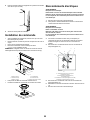
Exigences d’emplacement
REMARQUE: Le système d’extraction par le bas est installé
directement derrière la table de cuisson. Installer d’abord le système
d’extraction par le bas, puis la table de cuisson.
IMPORTANT: Observer les dispositions de tous les codes et
règlements en vigueur.
• Demander à un technicien qualié d’installer le système
d’extraction par le bas. C’est à l’installateur qu’incombe la
responsabilité de respecter les distances de séparation exigées,
spéciées sur la plaque signalétique de l’appareil. La plaque
signalétique est située à l’avant de l’appareil, audessus du
couvercle du boîtier de connexion.
• Le système d’extraction par le bas doit être installé à l’écart des
zones de forts courants d’air, telles que fenêtres, portes et évents
ou ventilateurs de chauffage.
• Respecter les dimensions indiquées pour les ouvertures à
découper dans les placards. Ces dimensions tiennent compte des
valeurs minimales des dégagements de séparation.
• Avant d’effectuer des découpes, consulter les instructions
d’installation fournies par le fabricant de la table de cuisson.
Vérier qu’à l’emplacement d’installation le système d’extraction
par le bas et la table de cuisson ne produiront pas d’interférence
avec les parois des placards, panneaux anti-éclaboussure, et
poteaux du colombage mural à l’arrière.
Vérier le respect de la distance minimale entre le bord avant du
plan de travail et le bord avant de la table de cuisson. La distance
minimale de séparation horizontale entre les placards muraux est
identique à la largeur du système d’extraction installé.
• Assurer l’étanchéité au niveau de chaque ouverture découpée
dans le plafond ou le mur pour l’installation du système
d’extraction par le bas.
• On doit disposer d’une prise de courant électrique reliée à la terre.
Voir la section “Spécications électriques”.
• Pour l’installation du conduit d’aspiration par le bas, il sera
nécessaire d’enlever le tiroir du placard et d’installer à demeure
une façade de tiroir sur le placard.
Conguration du placard:
Le système d’extraction par le bas est conçu pour une utilisation
dans un placard de profondeur 24” (61 cm). Certaines installations
nécessitent un plan de travail de largeur supérieure à 25” (63,5 cm).
Voir le tableau de dimensions de découpage pour plan de travail.
La profondeur maximale du placard mural est de 13” (33 cm). Les
placards muraux installés à coté du système d’extraction par le
bas doivent se trouver à 18” (45,7 cm) au-dessus de la surface de
cuisson.
Installation dans une résidence mobile
L’installation de ce système d’extraction par le bas doit satisfaire
aux exigences de la norme Manufactured Home Construction
Safety Standards, Titre 24 CFR, partie 328 (anciennement Federal
Standard for Mobile Home Construction and Safety, titre 24, HUD,
partie 280); lorsque cette norme n’est pas applicable, l’installation doit
satisfaire aux critères de la plus récente édition
de la norme Manufac-
tured Home Installation 1982 (Manufactured Home Sites, Communi-
ties and Setups) ANSI A225.1/NFPA 501A, ou des codes locaux.

19
Outils et piéces
Enlever l’emballage
ATTENTION
Enlever délicatement le carton, Porter des gants pour se protéger des
bords coupants.
AVERTISSEMENT
Enlever le lm de protection recouvrant le produit avant de commenc-
er l’opération.
Pièces fournies
• Système de ventilation rétractable avec moteur déjà installé
• Filtres a graise
• 2 - Pieds de soutien inférieurs
• 2 - Embouts
• Raccord de transition 6” de diamètre, avec clapet
• Clapet anti-reux rectangulaire de 3
1
⁄4”x10”
• Metalic garniture supérieure
• Ensemble de commande
• Sac de matériel avec:
• Guide et l’utilisation d’installation
• 1 - Tube de l rétractable
• 2 - Attaches en plastique
• 2 - Brides de montage
• 4 - Clips en plastique
• 7 - Clips adhésifs
• 8 - 4 x 8 mm vis de installation
• 11 - 4.5 x 13 mm vis de installation
• 3 - 3.5 x 9.5 mm vis de installation
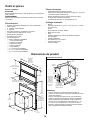
Dimensions du produit
Pièces nécessaires
• Câble d’alimentation électrique du domicile
• Connecteur de conduit (homologation UL ou CSA) de ½” (12,7 mm)
• 3 connecteurs de ls homologués UL
• Bouche de décharge murale ou à travers le toit avec clapet
correspondant au système d’évacuation
• Conduit d’évacuation de 6” ou rectangulaire 3
1
⁄4”x10”
Outillage nécessaire
• Niveau
• Perceuse et forets de1¼” (3.2 cm),⅛” (3.2 mm), et
5
⁄16” (7.9 mm)
pour avant trous
• Crayon
• Pince à dénuder ou couteau utilitaire
• Mètre-ruban ou règle
• Pince
• Pistolet à calfeutrage et composé de calfeutrage résistant
aux intempéries
• Cisaille de ferblantier
• Scie sauteuse ou scie à guichet
• Tournevis à lame plate
• Tournevis Phillips
Largeurs de la
garniture
supérieure:
30” (76.2 cm)
36” (91.4 cm)
13
1
⁄2” (34.3 cm)
Hauteur de l’évacuation
rétractable
27” (68.6 cm) pour modèle 30”
33” (83.8 cm) pour modèle 36”
1
1
⁄2”
(3.8 cm)
28
1
⁄2”
(72.6 cm)
13
1
⁄8”
(33.4 cm)
16
1
⁄2”
(42 cm)
10”
(25.4 cm)
2
1
⁄8”
(5.4 cm)
5
1
⁄4” (13.3 cm)
pour modèle 30”
8
1
⁄4” (21 cm)
pour modèle 36”
19
⁄32”
(1.5 cm)
Dimensions du placard
9
1
⁄2”
(24.4 cm)
1
⁄2” (1.27 cm)
minimale
Axe central
de l’ouverture
recevant la table
de cuisson
Placer le boîtier de
raccordement
électrique dans
l’angle arrière/gauche
au bas du placard.
Les découpes
correspondent
à un circuit
d’évacuation
rectangulaire
de 3
1
⁄4” x 10”
(8.3 x 25.4 cm)
ou rond de 6”
(15.2 cm).
21
5
⁄16”
(54.1 cm)
21
5
⁄16”
(54.1 cm)
REMARQUES:
• Pour les dimensions de l’ouverture recevant la table de
cuisson, voir les instructions du fabricant de la table de cuisson
(profondeur et largeur).
• Pour les ouvertures découpées pour le circuit d’évacuation,
utiliser les dimensions applicables à la situation d’installation.
• Circuits d’évacuation avec ventilateur monté à l’intérieur et
raccordé au conduit d’évacuation rectangulaire de 3¼” x 10”
(8,3 x 25,4 cm) ou circulaire de 6” (15,2 cm). Pour cette co
guration, l’emplacement des ouvertures à découper dépend
de la conguration d’installation spécique.

20
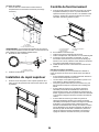
Dimensions des ouvertures à découper
IMPORTANT: Les plans de travail avec rebord avant arrondi ne sont
pas recommandés pour ces installations.
Certains modèles nécessitent un plan de travail de plus de 25” (63,5
cm); voir le tableau des dimensions de l’ouverture du plan de
travail. Pour éviter une erreur, avant de découper une ouverture, trac-
er le périmètre de la table de cuisson et des ouvertures à découper
sur le plan de travail.
Pour les dimensions des ouvertures, la position des ouvertures et le
détail des installations, voir les instructions d’installation de la table
de cuisson.
REMARQUE: Pour éviter d’éventuels problèmes de sifets pour la
ltration de l’air, il est recommandé de garder au minimum la distance
entre le table de cuisson et la hotte de ventilation (J).
Il est recommandé une application de scellant dans ce domaine.
D
E
B
C
F
G
H
A
I
A. Système d’extraction par le bas
B. Table de cuisson
C. Dimension du dépassement arrière de la
table de cuisson.
D. D = Dimension du dépassement arrière de la
table de cuisson (C) + 2
1
⁄2” [61 mm] (E)
E. 2
1
⁄2” (61 mm)
F. ¼” (6.4 mm) minimum
G. Plan de travail et panneau anti-écla-
boussure
H. ½” (12.7 mm) minimum
I. Seal la table de cuisson / downdraft
conjointe
Tableau des dimensions de l’ouverture
A
B
D
F
G
C
E
A. ½” (12.7 mm) min. jusqu’au panneau
antiéclaboussure ou mur arrière
B.
3
⁄4” (19.1 mm) maximum pour la
profondeur du panneau anti-éclaboussure
C. 27½” (70cm) sur les modèles de 30”
(76.2cm)
33½” (86cm) sur les modèles de 36”
(91.4cm)
D. D = E + 2
1
⁄2” (61 mm)
E. Dépassement arrière de la table de
cuisson
F. Ø 2
9
⁄16” (6.5 cm). La commande peut être
installé dans les deux côtés gauche ou
à droite.
G. Distance a la table de cuisson:
Minimale 4” (10 cm)
Maximale 8” (20 cm)
Exigences concernant l’évacuation
IMPORTANT : Avant d’effectuer des découpes, s’assurer qu’il y
a un dégagement convenable dans le mur ou le plancher pour le
système d’extraction.
• Utiliser un conduit métallique rigide.
• Le système doit décharger l’air à l’extérieur.
• Ne pas terminer le système d’extraction dans un grenier ou dans
un autre espace fermé.
• Ne pas utiliser une bouche de décharge murale de 4” (10,2 cm)
normalement utilisée pour un équipement de buanderie.
• Ne pas connecter 2 coudes ensemble.
• Ne pas utiliser un conduit de plastique ou en métal exible.
• La longueur du système d’évacuation et le nombre de coudes
doivent être réduits au minimum pour l’obtention de la meilleure
performance.
• Ne pas utiliser plus de trois coudes à 90°.
• Veiller à incorporer une section de conduit rectiligne d’au moins
24” (61 cm) entre deux raccords coudés adjacents.
• Au niveau de chaque jointure du système d’extraction, assurer
l’étanchéité avec les brides de serrage pour conduit.
• Autour de la bouche de décharge murale ou par le plancher à
l’extérieur, assurer l’étanchéité avec un produit de calfeutrage.
• Ne pas couper une solive ou un poteau du colombage. Si le
point de passage d’un système d’extraction correspond à la
position d’un poteau du colombage ou d’une solive, on doit
réaliser une structure de support appropriée.
• On déconseille l’emploi d’un conduit en métal exible. Si un
conduit de ce type doit être utilisé, on doit tenir compte du fait
que chaque pied de conduit exible compte comme 2 pi (0,6 m)
de conduit rigide métallique.
• Un raccord coudé exible compte comme deux raccords coudé
standard.
Longueur recommandée pour le système d’extraction :
Pour une conguration avec ventilateur monté à l’intérieur ou monté
à l’extérieur, la longueur du système d’extraction ne doit pas être
supérieure à la valeur maximum indiquée au tableau Longueur maxi-
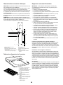
mum du système d’extraction. Voir “Calcul de la longueur du système
d’extraction” à la section “Méthodes d’extraction” des Instructions
d’installation.
Installations dans les régions au climat froid
On doit installer un clapet anti-retour supplémentaire à l’arrière pour
minimiser le reux d’air froid et incorporer un élément d’isolation ther-
mique pour minimiser la conduction de chaleur par l’intermédiaire du
conduit d’évacuation, de l’intérieur de la maison à l’extérieur. Le clapet
anti-retour doit être placé du côté air froid de la résistance thermique.
L’élément d’isolation thermique doit être aussi proche que possible de
l’endroit où le circuit d’évacuation s’introduit dans la partie chauffée
de la maison.
Air d’appoint
Le code du bâtiment local peut exiger l’emploi d’un système d’appoint
d’air lors de l’emploi d’un ventilateur d’extraction dont la capacité d’as-
piration est supérieure à un débit (pieds cubes par minute) spécié.
Le débit spécié en pieds cubes par minute varie d’une juridiction à
l’autre. Consulter un professionnel des installations de chauffage ven-
tilation/climatisation au sujet des exigences spéciques applicables
dans la juridiction locale.
La page charge ...
La page charge ...
La page charge ...
La page charge ...
La page charge ...
La page charge ...
La page charge ...
La page charge ...
La page charge ...
La page charge ...
La page charge ...
La page charge ...
La page charge ...
La page charge ...
La page charge ...
La page charge ...
La page charge ...
La page charge ...
La page charge ...
La page charge ...
La page charge ...
La page charge ...
La page charge ...
La page charge ...
-
 1
1
-
 2
2
-
 3
3
-
 4
4
-
 5
5
-
 6
6
-
 7
7
-
 8
8
-
 9
9
-
 10
10
-
 11
11
-
 12
12
-
 13
13
-
 14
14
-
 15
15
-
 16
16
-
 17
17
-
 18
18
-
 19
19
-
 20
20
-
 21
21
-
 22
22
-
 23
23
-
 24
24
-
 25
25
-
 26
26
-
 27
27
-
 28
28
-
 29
29
-
 30
30
-
 31
31
-
 32
32
-
 33
33
-
 34
34
-
 35
35
-
 36
36
-
 37
37
-
 38
38
-
 39
39
-
 40
40
-
 41
41
-
 42
42
-
 43
43
-
 44
44


ELICA ERS630S1 Guide d'installation
- Catégorie
- Hottes
- Taper
- Guide d'installation
dans d''autres langues
- English: ELICA ERS630S1 Installation guide
- español: ELICA ERS630S1 Guía de instalación