
COOLING / REFROIDISSEMENT / KÜHLUNG / RAFFREDDAMENTO /
REFRIGERACIÓN / REFRIGERAÇÃO / 冷却
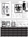
CONTROL PANEL AND KEYPAD / PANNEAU OPÉRATEUR / STEUERTAFEL UND TASTENFELD / PANNELLO DI CONTROLLO E PANNELLO DI COMANDO / CUADRO DE CONTROL Y PANEL / PAINEL DE CONTROLE E TECLADO / 控制面板和键盘
CABLE INSTALLATION / INSTALLATION DES CÂBLES /
KABELINSTALLATION / INSTALLAZIONE DEI CAVI /
INSTALACIÓN DE LOS CABLES / INSTALAÇÃO DO CABO / 电缆安装
The minimum clearance (mm) around the drive
Dégagement minimal (mm) autour du convertisseur
Der Mindestabstand (mm) um den Umrichter herum
Distanza minima (mm) intorno all’inverter
La separación mínima (mm) alrededor del convertidor
Espaço livre mínimo (mm) ao redor do conversor
变频器周围的最小间隙 (mm)
FRAME A B C
All types 80 160 60
L1
L2
L3
Mains
Réseau
Netz
Rete elettrica
Red eléctrica
Rede elétrica
电源
U/T1
V/T2
W/T3
Motor
Moteur
Motor
Motore
Motor
Motor
电机
DC+
DC-
DC bus terminals
Borne de bus DC
DC-Bus-Anschlüsse
Morsetti DC bus
Terminales de bus de CC
Terminais do barramento DC
直流总线端子
VACON
®
100 X AC DRIVES
QUICK GUIDE
EN
FR
DE
IT
PT-
BR
ES
ZH
GUIDE RAPIDE
KURZANLEITUNG
GUIDA RAPIDA
GUÍA RÁPIDA
GUIA RÁPIDO
快速指南
Download and read Vacon 100 X Installation Manual at:
Téléchargez et lisez le manuel d’installation de Vacon
100 X, convertisseurs de fréquence sur :
Lesen Sie das Installationshandbuch für den Vacon 100 X,
das zum Download bereitsteht unter:
Scaricare e leggere il Manuale di installazione Vacon 100 X,
all’indirizzo:
Descargue y lea el Manual de instalación de Vacon 100 X,
unidades en:
Baixe e leia o Manual de Instalação do Vacon 100 X,
conversores de frequência em:
可在以下位置下载和阅读 Vacon 100 X 安装手册:
http://drives.danfoss.com/knowledge-center/techni-
cal-documentation/
A The graphical display L’affichage graphique Das Grafik-Display Il display grafico La pantalla gráfica A exibição gráfica
图形显示屏
1 The location field Champ de localisation Das Positionsfeld Il campo della posizione El campo de ubicación O campo de localização
位置字段
2 An activated group or item Groupe ou élément activé Aktivierte Gruppe oder aktiviertes Element Un gruppo o un elemento attivato Un grupo o elemento activado Um grupo ou item ativado
激活的组或项目
3 The number of items in the group in question Nombre d’éléments dans le groupe en question Anzahl der Elemente in der betreffenden Gruppe Il numero di elementi nel gruppo in questione El número de elementos del grupo en cuestión O número de itens no grupo em questão
所述组中的项目数量
4 The first status field: STOP/RUN Premier champ d’état : ARRÊT/MARCHE Das erste Statusfeld: STOPP/BETRIEB Il primo campo dello stato: Arresto/Marcia El primer campo de estado: PARO/MARCHA O primeiro campo de status: PARADO/EM FUNCIONAMENTO
第一个状态字段
5 The rotation direction Sens de rotation Die Drehrichtung des Motors La direzione di rotazione del motore El sentido de giro del motor A direção de rotação do motor
电机的旋转方向
6 The second status field: READY/NOT READY/FAULT Deuxième champ d’état : PRÊT/PAS PRÊT/DÉFAUT Das zweite Statusfeld: BEREIT/NICHT BEREIT/FEHLER Il secondo campo dello stato: Pronto/Non pronto/Guasto El segundo campo de estado: LISTO/NO LISTO/FALLO O segundo campo de status: PRONTO/NÃO PRONTO/FALHA
第二个状态字段
7 The alarm field Champ d’alarme Das Alarmfeld Il campo di allarme El campo de alarma O campo de alarme
警报字段
8 The control place Source de commande Das Steuerplatzfeld Il campo della postazione di controllo El campo del lugar de control O campo de local de controle
控制位置字段
B The text display L’affichage textuel Das Text-Display Il display di testo. La pantalla de texto A exibição de texto
文本显示屏
9 The indicators of status Indicateurs d’état Die Statusanzeigen Gli indicatori di stato Los indicadores de estado Os indicadores de status
状态指示灯
10 The indicators of alarm and fault Indicateurs d’alarme et de défaut Die Alarm- und Fehleranzeigen Gli indicatori di allarme e guasto Los indicadores de alarmas y fallos Os indicadores de alarme e falha
警报和故障指示灯
11 The name of the group or item Nom du groupe ou de l’élément Der Name der Gruppe oder des Elements Il nome del gruppo o dell’elemento El nombre del grupo o elemento O nome do grupo ou item
的组或项目的名称
12 The current location in the menu Emplacement actuel dans le menu Die aktuelle Position im Menü La posizione corrente nel menu corrente La ubicación actual en el menú A localização atual no menu
当前在菜单中的位置
13 The indicators of the rotation direction Indicateurs du sens de rotation Die Drehrichtungsanzeigen Gli indicatori della direzione di rotazione Los indicadores del sentido de giro Os indicadores da direção de rotação
旋转方向指示灯
14 The indicators of the control place Indicateurs de la source de commande Die Steuerplatzanzeigen Gli indicatori della postazione di controllo Los indicadores del lugar de control Os indicadores do local de controle
控制位置指示灯
C The buttons of the keypad Boutons du panneau opérateur Die Tasten des Tastenfelds Pulsanti del pannello di comando Los botones del panel Os botões do teclado
键盘上的按钮
15 The BACK/RESET button Touche BACK/RESET BACK/RESET-Taste Pulsante BACK/RESET El botón BACK/RESET O botão de voltar/redefinição
“后退/重置”按钮
16 The OK button Touche OK OK-Taste Pulsante OK El botón OK O botão OK
“确定”按钮
17 The arrow button UP Touche HAUT Pfeiltaste NACH OBEN Pulsante freccia Su El botón de flecha ARRIBA O botão de seta PARA CIMA
向上箭头按钮
18 The FUNCT button Touche FUNCT FUNCT-Taste Pulsante FUNCT El botón FUNCT O botão FUNCT FUNCT 按钮
19 The arrow button RIGHT Touche DROITE Pfeiltaste NACH RECHTS Pulsante freccia Destra El botón de flecha DERECHA O botão de seta PARA A DIREITA
向右箭头按钮
20 The START button Touche MARCHE START-Taste Pulsante Avvio El botón START O Botão INICIAR
启动按钮
21 The arrow button DOWN Touche BAS Pfeiltaste NACH UNTEN Pulsante freccia Giù El botón de flecha ABAJO O botão de seta PARA BAIXO
向下箭头按钮
22 The STOP button Touche ARRÊT STOP-Taste Pulsante Arresto El botón STOP O botão PARAR
停止按钮
23 The arrow button LEFT Touche GAUCHE Pfeiltaste NACH LINKS Pulsante freccia Sinistra El botón de flecha IZQUIERDA O botão de seta PARA A ESQUERDA
向左箭头按钮
FUNCT (18)
Use it to change the rotation direction of the motor, access the control page, and change the control place.
Utilisez cette touche pour inverser le sens de rotation du moteur, accéder à la page de commande et modifier la source de commande.
Drehrichtung des Motors ändern, Steuerungsseite aufrufen und Steuerplatz ändern.
Utilizzarlo per modificare la direzione di rotazione del motore, per accedere alla pagina di controllo e per cambiare le impostazioni di controllo.
Utilícelo para cambiar el sentido de giro del motor, acceder a la página de control y cambiar el lugar de control.
Use-o para alterar a direção de rotação do motor, acessar a página de controle e alterar o local de controle.
用于更改电机的旋转方 向、访问控制页面和更改控制位置。有关 更多信息
Changing the control place:
1. 2.
‘Local/Remote’
3.
OK
4.
‘Local’ or ‘Remote’
5.
OK
Modification de la source de commande : ‘Local/Distance’ ‘Local’ ou ‘Distance’
Ändern des steuerplatzes: ‘Ort/Fern’ ‘Ort’ oder ‘Fern’
Cambio della impostazioni di controllo: ‘Locale/Remoto’ ‘Locale’ o ‘Remoto’
Cambio del lugar de control: ‘Local/Remoto’ ‘Local’ o ‘Remoto’
Alteração de local de controle: ‘Local/Remoto’ ‘Local’ ou ‘Remoto’
更改控制位置: ‘本地/远程’ ‘本地’或 ‘远程’
The earth conductor
Le conducteur de terre
Erdungsleiter
Conduttore di terra
El conductor de toma a tierra
Condutor de aterramento
接地导线
R+
R-
Brake resistor terminals
Bornes de la résistance de freinage
Bremswiderstandsklemmen
Morsetti per la Resistenza di frenatura
Terminales de resistencia de freno
Terminais do resistor de frenagem
制动电阻器端子
Example: MM5
BC
A A A
A. C.B.
1
45 67
81
5
23
11
12
22
19
20211413
16 17 18910
2
3
L1 L2 L3
DC- DC+/R+ R-
U/T1 V
/
T2 W
/
T3
PE PE
PES
W/
T3
V/
T2
U/
T1
R-
DC+
/R+
DC-
L3 L2 L1

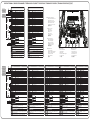
CONTROL TERMINALS / BORNES DE COMMANDE / STEUERANSCHLÜSSE /MORSETTI DI CONTROLLO / TERMINALES DE CONTROL / TERMINAIS DE CONTROLE / 控制端子
1, 2
Control terminals 1-30
Bornes de commande 1-30
Steuerklemmen 1-30
Morsetti di controllo 1-30
Bornes de control 1-30
Terminais de controle 1-30
控制终端 1-30
3
Relay terminals
Bornes relais
Relaisklemmen
Morsetti relè
Bornes de relé
Terminais de relé
继电器端子
4
Thermistor input
Entrée thermistance
Thermistoreingang
Ingresso termistore
Entrada del termistor
Entrada do termistor
热敏电阻输入
5
Option boards
Cartes en option
Optional expansion modules
Slot per schede opzionali
Tarjetas opcionales
Placas opcionais
选件板
Standard I/O
Terminal Signal
1 +10 Vref Reference output
2 AI1+ Analogue input, voltage or current
3 AI1- Analogue input common
4 AI2+ Analogue input, voltage or current
5 AI2- Analogue input common
6 24 Vout 24V aux. voltage
7 GND I/O ground
8 DI1 Digital input 1
9 DI2 Digital input 2
10 DI3 Digital input 3
11 CM Common for DI1-DI6
12 24 Vout 24V aux. voltage
13 GND I/O ground
14 DI4 Digital input 4
15 DI5 Digital input 5
16 DI6 Digital input 6
17 CM Common for DI1-DI6
18 AO1+ Analogue output, voltage or current
19 AO-/GND Analogue output common
30 +24 Vin 24V auxiliary input voltage
A RS485 Serial bus, negative
B RS485 Serial bus, positive
21 RO1/1 Relay output 1
22 RO1/2
23 RO1/3
24 RO2/1 Relay output 2
25 RO2/2
26 RO2/3
28 TI1+
Thermistor input
29 TI1-
STO input
S1 Isolated digital input 1
(inter-changeable polarity); +24V ±20% 10...15mA
G1
S2 Isolated digital input 2
(inter-changeable polarity); +24V ±20% 10...15mA
G2
STO feedback
F+
Isolated feedback
(CAUTION! Polarity to be respected); +24V ±20%
F-
Isolated feedback
(CAUTION! Polarity to be respected); GND
Standard-E/A
Klemme Signal
1 +10 Vref Bezugsausgang
2 AI1+ Analogeingang, Spannung oder Strom
3 AI1- Gemeinsame Masse Analogeingang
4 AI2+ Analogeingang, Spannung oder Strom
5 AI2- Gemeinsame Masse Analogeingang
6 24 Vout 24V Hilfsspannung
7 GND E/A-Masse
8 DI1 Digitaleingang 1
9 DI2 Digitaleingang 2
10 DI3 Digitaleingang 3
11 CM Gemeinsame Masse für DI1-DI6
12 24 Vout 24V Hilfsspannung
13 GND E/A-Masse
14 DI4 Digitaleingang 4
15 DI5 Digitaleingang 5
16 DI6 Digitaleingang 6
17 CM Gemeinsame Masse für DI1-DI6
18 AO1+ Analogausgang, Spannung oder Strom
19 AO-/GND Gemeinsame Masse Analogausgang
30 +24 Vin 24V Stützspannung
A RS485 Serieller Bus, negativ
B RS485 Serieller Bus, positiv
21 RO1/1 Relaisausgang1
22 RO1/2
23 RO1/3
24 RO2/1 Relaisausgang2
25 RO2/2
26 RO2/3
28 TI1+
Thermistoreingang
29 TI1-
STO-Eingang
S1 Isolierter Digitaleingang 1
(Pola rität wechselbar); +24V ±20% 10...15mA
G1
S2 Isolierter Digitaleingang 2
(Polarität wechselbar); +24V ±20% 10...15mA
G2
STO Rückmeldung
F+
Isolierte Rückführung
(VORSICHT! Polarität muss eingehalten werden); +24V ±20%
F-
Isolierte Rückführung
(VORSICHT! Polarität muss eingehalten werden); GND
Reference
potentiometer
1...10 kΩ
Reference
potentiometer
1...10 kΩ
Remote
reference
4...20mA/0...10V
Remote
reference
4...20mA/0...10V
mA
mA
RUN
RUN
E/S de base
Borne Signal
1 +10 Vref Tension réf. en sortie
2 AI1+ Entrée analogique, tension ou intensité
3 AI1- Commun entrée analogique
4 AI2+ Entrée analogique, tension ou intensité
5 AI2- Commun entrée analogique
6 24 Vout Tension aux. 24V
7 GND Masse (GND)
8 DI1 Entrée logique 1
9 DI2 Entrée logique 2
10 DI3 Entrée logique 3
11 CM Commun pour DI1-DI6
12 24 Vout Tension aux. 24V
13 GND Masse (GND)
14 DI4 Entrée logique 4
15 DI5 Entrée logique 5
16 DI6 Entrée logique 6
17 CM Commun pour DI1-DI6
18 AO1+ Sortie analogique, tension ou intensité
19 AO-/GND Commun de sortie analogique
30 +24 Vin 24V tension d’entrée auxiliaire
A RS485 Bus série, négatif
B RS485 Bus série, positif
21 RO1/1 Sortie relais 1
22 RO1/2
23 RO1/3
24 RO2/1 Sortie relais 2
25 RO2/2
26 RO2/3
28 TI1+
Entrée thermistance
29 TI1-
Entrée STO
S1 Entrée logique isolée 1
(polarité interchangeable) ; +24V ±20% 10...15mA
G1
S2 Entrée logique isolée 2
(polarité interchangeable) ; +24V ±20% 10...15mA
G2
Retour STO
F+
Sortie isolée
(ATTENTION ! Polarité à respecter) ; +24V ±20%
F-
Sortie isolée
(ATTENTION ! Polarité à respecter) ; GND
I/O Standard
Morsetto Segnale
1 +10 Vref Uscita di riferimento
2 AI1+ Ingresso analogico, tensione o corrente
3 AI1- Comune ingresso analogico
4 AI2+ Ingresso analogico, tensione o corrente
5 AI2- Comune ingresso analogico
6 24 Vout Tensione aus. 24V
7 GND Massa I/O
8 DI1 Ingresso digitale 1
9 DI2 Ingresso digitale 2
10 DI3 Ingresso digitale 3
11 CM Comune for DI1-DI6
12 24 Vout Tensione aus. 24V
13 GND Massa I/O
14 DI4 Ingresso digitale 4
15 DI5 Ingresso digitale 5
16 DI6 Ingresso digitale 6
17 CM Comune per DI1-DI6
18 AO1+ Uscita analogica, tensione o corrente
19 AO-/GND Comune uscita analogica
30 +24 Vin Ingresso di tensione aus. 24V
A RS485 Bus seriale, negativo
B RS485 Bus seriale, positivo
21 RO1/1 Uscita relè 1
22 RO1/2
23 RO1/3
24 RO2/1 Uscita relè 2
25 RO2/2
26 RO2/3
28 TI1+
Ingresso termistore
29 TI1-
Ingresso STO
S1 Ingresso digitale isolato 1
(polarità interscambiabile); +24V ±20% 10...15mA
G1
S2 Ingresso digitale isolato 2
(polarità interscambiabile); +24V ±20% 10...15mA
G2
Feedback STO
F+
Feedback isolato
(ATTENZIONE! La polarità deve essere rispettata); +24V ±20%
F-
Feedback isolato
(ATTENZIONE! La polarità deve essere rispettata); GND
E/S estándares
Borne Señal
1 +10 Vref Salida de referencia
2 AI1+ Entrada analógica, tensión o corriente
3 AI1- Potencial común de la entrada analógica
4 AI2+ Entrada analógica, tensión o corriente
5 AI2- Potencial común de la entrada analógica
6 24 Vout Tensión aux. de 24 V
7 GND Tierra E/S
8 DI1 Entrada digital 1
9 DI2 Entrada digital 2
10 DI3 Entrada digital 3
11 CM Potencial común para DI1-DI6
12 24 Vout Tensión aux. de 24 V
13 GND Tierra E/S
14 DI4 Entrada digital 4
15 DI5 Entrada digital 5
16 DI6 Entrada digital 6
17 CM Potencial común para DI1-DI6
18 AO1+ Salida analógica, tensión o corriente
19 AO-/GND Potencial común de lavsalida analógica
30 +24 Vin Tensión de entrada auxiliar 24 V
A RS485 Bus serial, negativo
B RS485 Bus serial, positivo
21 RO1/1 Salida de relé 1
22 RO1/2
23 RO1/3
24 RO2/1 Salida de relé 2
25 RO2/2
26 RO2/3
28 TI1+
Entrada del termistor
29 TI1-
Entrada de STO
S1 Entrada digital 1 aislada
(polaridad intercambiable); +24 V ±20% 10...15 mA
G1
S2 Entrada digital 2 aislada
(polaridad intercambiable); +24 V ±20% 10...15 mA
G2
Valor actual de STO
F+
Realimentación aislada
(¡ATENCIÓN! Respetar la polaridad); +24 V ±20%
F-
Realimentación aislada
(¡ATENCIÓN! Respetar la polaridad); GND
E/S padrão
Terminal Sinal
1 +10 Vref Saída de referência
2 AI1+ Entrada analógica, tensão ou corrente
3 AI1- Entrada analógica comum
4 AI2+ Entrada analógica, tensão ou corrente
5 AI2- Entrada analógica comum
6 24 Vout Voltagem aux. de 24V
7 GND Terra de E/S
8 DI1 Entrada digital 1
9 DI2 Entrada digital 2
10 DI3 Entrada digital 3
11 CM Comum para DI1-DI6
12 24 Vout Voltagem aux. de 24V
13 GND Terra de E/S
14 DI4 Entrada digital 4
15 DI5 Entrada digital 5
16 DI6 Entrada digital 6
17 CM Comum para DI1-DI6
18 AO1+ Saída analógica, tensão ou corrente
19 AO-/GND Saída analógica comum
30 +24 Vin Voltagem de entrada auxiliar de 24V
A RS485 Barramento serial, negativo
B RS485 Barramento serial, positivo
21 RO1/1 Saída de relé 1
22 RO1/2
23 RO1/3
24 RO2/1 Saída de relé 2
25 RO2/2
26 RO2/3
28 TI1+
Entrada do termistor:
29 TI1-
Entrada STO
S1 Entrada digital isolada 1
(polaridade intercambiável); +24 V ±20% 10...15 mA
G1
S2 Entrada digital isolada 2
(polaridade intercambiável); +24 V ±20% 10...15 mA
G2
Realimentação STO
F+
Realimentação isolada
(CUIDADO! Polaridade a ser respeitada); +24 V ±20%
F-
Realimentação isolada
(CUIDADO! Polaridade a ser respeitada); GND
标准 I/O
端子 信号
1 +10 Vref
参考输出
2 AI1+
模拟输入,电压或电流
3 AI1-
模拟输入公共端
4 AI2+
模拟输入,电压或电流
5 AI2-
模拟输入公共端
6 24 Vout 24V 辅助电压
7 GND I/O 地
8 DI1 数字输入 1
9 DI2 数字输入 2
10 DI3 数字输入 3
11 CM DI1-DI6 共用
12 24 Vout 24V 辅助电压
13 GND I/O 地
14 DI4 数字输入 4
15 DI5 数字输入 5
16 DI6 数字输入 6
17 CM DI1-DI6 共用
18 AO1+
模拟输出,电压或电流
19 AO-/GND
模拟输出地
30 +24 Vin 24V 辅助输入电压
A RS485
串行总线,负极
B RS485
串行总线,正极
21 RO1/1 继电器输出 1
22 RO1/2
23 RO1/3
24 RO2/1 继电器输出 2
25 RO2/2
26 RO2/3
28 TI1+
热敏电阻输入
29 TI1-
STO 输入
S1
隔离数字输入 1
(可内部更换电极);+24V ±20% 10...15mA
G1
S2
隔离数字输入 2
(可内部更换电极);+24V ±20% 10...15mA
G2
STO 反馈
F+
隔离反馈
(小心!注意电极);+24 V ±20%
F-
隔离反馈
(小心!注意电极);GND
6
STO Terminals
Bornier carte STOS
STO-Klemmen
Morsetti STO
Bornes de parada segura
Terminais STO
STO 端子
7
Ethernet Terminal
Borne Ethernet
Ethernetanschluss
Connettore Ethernet
Borne de Ethernet
Terminal Ethernet
以太网端子
1
5
4
5
6
7
2
3
-
 1
1
-
 2
2


Vacon VACON 100 X Guide d'installation
- Taper
- Guide d'installation
- Ce manuel convient également à
dans d''autres langues
- italiano: Vacon VACON 100 X Guida d'installazione
- español: Vacon VACON 100 X Guía de instalación
- português: Vacon VACON 100 X Guia de instalação