Miller MH030157G Le manuel du propriétaire
- Catégorie
- Système de soudage
- Taper
- Le manuel du propriétaire
Ce manuel convient également à

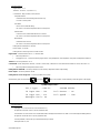
ProHeat 35
Processes
Description
Induction Heating Power Source
Induction Heating
OM-222166AH 2016−12
File: Induction Heating
Visit our website at
www.MillerWelds.com
CE And Non CE Models
[
(For Stock Nos. 907271, 907298, and 907432)

Miller Electric manufactures a full line
of welders and welding related equipment.
For information on other quality Miller
products, contact your local Miller distributor to receive the latest full
line catalog or individual specification sheets. To locate your nearest
distributor or service agency call 1-800-4-A-Miller, or visit us at
www.MillerWelds.com on the web.
Thank you and congratulations on choosing Miller. Now you can get
the job done and get it done right. We know you don’t have time to do
it any other way.
That’s why when Niels Miller first started building arc welders in 1929,
he made sure his products offered long-lasting value and superior
quality. Like you, his customers couldn’t afford anything less. Miller
products had to be more than the best they could be. They had to be the
best you could buy.
Today, the people that build and sell Miller products continue the
tradition. They’re just as committed to providing equipment and service
that meets the high standards of quality and value established in 1929.
This Owner’s Manual is designed to help you get the most out of your
Miller products. Please take time to read the Safety precautions. They
will help you protect yourself against potential hazards on the worksite.
We’ve made installation and operation quick
and easy. With Miller you can count on years
of reliable service with proper maintenance.
And if for some reason the unit needs repair,
there’s a Troubleshooting section that will
help you figure out what the problem is. The
parts list will then help you to decide the
exact part you may need to fix the problem.
Warranty and service information for your
particular model are also provided.
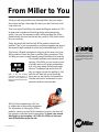
Miller is the first welding
equipment manufacturer in
the U.S.A. to be registered to
the ISO 9001 Quality System
Standard.
Working as hard as you do
− every power source from
Miller is backed by the most
hassle-free warranty in the
business.
From Miller to You
Mil_Thank 2009−09

TABLE OF CONTENTS
SECTION 1 − SAFETY PRECAUTIONS − READ BEFORE USING 1.................................
1-1. Symbol Usage 1.......................................................................
1-2. Induction Heating Hazards 1.............................................................
1-3. Additional Symbols for Installation, Operation, and Maintenance 2..............................
1-4. California Proposition 65 Warnings 3......................................................
1-5. Principal Safety Standards 3.............................................................
1-6. EMF Information 3.....................................................................
SECTION 2 − CONSIGNES DE SÉCURITÉ − LIRE AVANT UTILISATION 4..........................
2-1. Signification des symboles 4.............................................................
2-2. Dangers relatifs au soudage à l’arc 4......................................................
2-3. Dangers supplémentaires en relation avec l’installation, le fonctionnement et la maintenance 5.....
2-4. Proposition californienne 65 Avertissements 6..............................................
2-5. Principales normes de sécurité 6.........................................................
2-6. Informations relatives aux CEM 6.........................................................
SECTION 3 − DEFINITIONS 7..................................................................
3-1. Additional Safety Symbols And Definitions 7................................................
3-2. Miscellaneous Symbols And Definitions 9..................................................
SECTION 4 − SPECIFICATIONS 10..............................................................
4-1. Serial Number and Rating Label Location 10.................................................
4-2. Specifications 10........................................................................
4-3. Environmental Specifications 10...........................................................
SECTION 5 − INSTALLATION 12................................................................
5-1. Selecting A Location 12..................................................................
5-2. Dimensions And Weights 12..............................................................
5-3. Electrical Service Guide 13...............................................................
5-4. Connecting 3-Phase Input Power For 460/575 Volt Models 14..................................
5-5. Connecting 3-Phase Input Power For 400/460 Volt IEC And CE Models 16.......................
5-6. Coolant Jumper Connections 17...........................................................
5-7. Power Source Output Connections 18......................................................
5-8. Remote 14 Receptacle RC14 Information and Connections 19.................................
5-9. Remote 14 Socket Information 19..........................................................
5-10. Temperature Recorder Receptacle RC9 Information And Connections 20........................
5-11. Temperature Recorder Socket Information 20................................................
5-12. Secondary Insulation Protection 21........................................................
5-13. 115 Volt AC Duplex Receptacle And Supplementary Protector 22...............................
5-14. Locating Thermocouples 22..............................................................
5-15. Attaching Welded Thermocouples 24.......................................................
5-16. Using Contact Thermocouple Sensors 25...................................................
5-17. Using Non−contact Temperature Sensors 25................................................
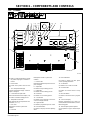
SECTION 6 − COMPONENTS AND CONTROLS 26................................................
6-1. Controls 26............................................................................
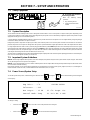
SECTION 7 − SETUP AND OPERATION 27.......................................................
7-1. Safety Equipment 27....................................................................
7-2. System Description 27...................................................................
7-3. Important System Guidelines 27...........................................................
7-4. Power Source/System Setup 27...........................................................
7-4-1.Factory Defaults 29...................................................................
7-5. Programming 29........................................................................
7-5-1.Temperature-Based Control 29..........................................................

TABLE OF CONTENTS (continued)
7-5-1-1. Preheat 29.....................................................................
7-5-1-2. Bake-Out 30....................................................................
7-5-1-3. PWHT (Post-Weld Heat Treat) 31..................................................
7-5-1-4. PWHT Operation 32.............................................................
7-5-1-5. Custom Program 32.............................................................
7-5-2.Remote Control 36....................................................................
7-5-3.Power vs Time Control 36..............................................................
7-5-4.Manual Control 36....................................................................
7-5-5.Rolling Inductor—Manual Or Temperature Control Mode 37..................................
7-6. Run Status 39..........................................................................
7-6-1.Temperature Based Control 39..........................................................
7-6-1-1. Preheat, Bake-Out And PWHT Run Status Screen 39.................................
7-6-1-2. Custom Program (Not Applicable With Rolling Inductor) 39.............................
7-6-2.Manual Control 40....................................................................
7-6-3.Remote Control 40....................................................................
7-6-4.Power vs Time Control 40..............................................................
7-7. Parameters 40..........................................................................
7-8. Cooler 41..............................................................................
7-9. Real-Time Operation 41..................................................................
7-10. System Operating Characteristics 44.......................................................
SECTION 8 − MAINTENANCE 46................................................................
8-1. Routine Maintenance 46.................................................................
8-2. Calibration Verification Equipment 47.......................................................
8-3. Calibration Verification Procedure 47.......................................................
8-3-1.Initial Set Up 47......................................................................
8-3-2.TC Input/Output Check 47.............................................................
8-3-3.Finishing Procedure 48................................................................
SECTION 9 − SAFETY PRECAUTIONS FOR SERVICING 51........................................
9-1. Symbol Usage 51.......................................................................
9-2. Servicing Hazards 51....................................................................
9-3. California Proposition 65 Warnings 52......................................................
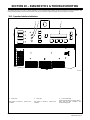
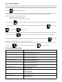
SECTION 10 − DIAGNOSTICS & TROUBLESHOOTING 53.........................................
10-1. Operator Interface Indicators 53...........................................................
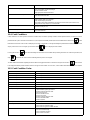
10-2. Limit Conditions 54......................................................................
10-3. Limit Condition Codes 54.................................................................
10-4. Fault Conditions 55......................................................................
10-5. Fault Condition Codes 55.................................................................
10-6. Infrared Sensor Troubleshooting Guide 57..................................................
10-7. System Diagnostic Screens 57............................................................
10-8. ProHeat 35 Firmware Versions And Compatibility 59..........................................
10-9. Removing Wrapper and Measuring Input Capacitor Voltage 60.................................
10-10. Blowing Out Inside Of Unit 61..........................................................
SECTION 11 − ELECTRICAL DIAGRAM 62.......................................................
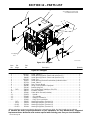
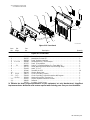
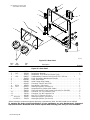
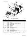
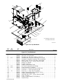
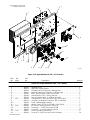
SECTION 12 − PARTS LIST 64..................................................................
WARRANTY

DECLARATION OF CONFORMITY
for European Community (CE marked) products.
MILLER Electric Mfg. Co., 1635 Spencer Street, Appleton, WI 54914 U.S.A. declares that the
product(s) identified in this declaration conform to the essential requirements and provisions of
the stated Council Directive(s) and Standard(s).
Product/Apparatus Identification:
Product
Stock Number
PROHEAT 35 W/TEMPERATURE CONTROL
400460V, CE
907432
Council Directives:
• 2006/95/EC Low Voltage
• 2004/108/EC Electromagnetic Compatibility
• 2011/65/EU Restriction of the use of certain hazardous substances in electrical and electronic equipment
Standards:
• IEC 609741:2005 Arc welding equipment – Part 1: Welding power sources
• IEC 6097410:2007 Arc Welding Equipment – Part 10: Electromagnetic compatibility (EMC) requirements
• EN 50445:2008 Product family standard to demonstrate compliance of equipment for resistance welding,
arc welding and allied processes with the basic restrictions related to human exposure to electromagnetic
fields (0 Hz – 300Hz)
Signatory:
_____________________________________ ___________________________________________
David A. Werba Date of Declaration
October 8, 2012
240667D


OM-222166 Page 1
SECTION 1 − SAFETY PRECAUTIONS − READ BEFORE USING
ihom _2015-09
Protect yourself and others from injury — read, follow, and save these important safety precautions and operating instructions.
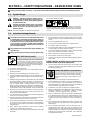
1-1. Symbol Usage
DANGER! − Indicates a hazardous situation which, if
not avoided, will result in death or serious injury. The
possible hazards are shown in the adjoining symbols
or explained in the text.
Indicates a hazardous situation which, if not avoided,
could result in death or serious injury. The possible
hazards are shown in the adjoining symbols or ex-
plained in the text.
NOTICE − Indicates statements not related to personal injury.
. Indicates special instructions.
This group of symbols means Warning! Watch Out! ELECTRIC
SHOCK, MOVING PARTS, and HOT PARTS hazards. Consult sym-
bols and related instructions below for necessary actions to avoid the
hazards.
1-2. Induction Heating Hazards
The symbols shown below are used throughout this manual
to call attention to and identify possible hazards. When you
see the symbol, watch out, and follow the related instructions
to avoid the hazard. The safety information given below is
only a summary of the more complete safety information
found in the Safety Standards listed in Section 1-5. Read and
follow all Safety Standards.
Only qualified persons should install, operate, maintain, and
repair this unit.
During operation, keep everybody, especially children, away.
ELECTRIC SHOCK can kill.
Touching live electrical parts can cause fatal shocks
or severe burns. The power circuit and output bus
bars or connections are electrically live whenever
the output is on. The input power circuit and machine
internal circuits are also live when power is on. Incorrectly installed or
improperly grounded equipment is a hazard.
D Do not touch live electrical parts.
D Enclose any connecting bus bars and coolant fittings to prevent
unintentional contact.
D Wear dry, hole-free insulating gloves and body protection.
D Insulate yourself from work and ground using dry insulating mats or
covers big enough to prevent any physical contact with the work or
ground.
D Additional safety precautions are required when any of the following
electrically hazardous conditions are present: in damp locations or
while wearing wet clothing; on metal structures such as floors, grat-
ings, or scaffolds; when in cramped positions such as sitting,
kneeling, or lying; or when there is a high risk of unavoidable or acci-
dental contact with the workpiece or ground. For these conditions,
see ANSI Z49.1 listed in Safety Standards. And, do not work alone!
D Disconnect input power before installing or servicing this equip-
ment. Lockout/tagout input power according to OSHA 29 CFR
1910.147 (see Safety Standards).
D Use only nonconductive coolant hoses with a minimum length of 18
inches (457 mm) to provide isolation.
D Properly install, ground, and operate this equipment according to its
Owner’s Manual and national, state, and local codes.
D Always verify the supply ground − check and be sure that input pow-
er cord ground wire is properly connected to ground terminal in
disconnect box or that cord plug is connected to a properly grounded
receptacle outlet.
D When making input connections, attach proper grounding
conductor first − double-check connections.
D Keep cords dry, free of oil and grease, and protected from hot metal
and sparks.
D Frequently inspect input power cord and ground conductor for dam-
age or bare wiring – replace immediately if damaged – bare wiring
can kill.
D Turn off all equipment when not in use.
D Do not use worn, damaged, undersized, or repaired cables.
D Do not drape cables over your body.
D Do not touch power circuit if you are in contact with the work, ground,
or another power circuit from a different machine.
D Use only well-maintained equipment. Repair or replace damaged
parts at once. Maintain unit according to manual.
D Wear a safety harness if working above floor level.
D Keep all panels and covers securely in place.
D Use GFCI protection when operating auxiliary equipment in damp or
wet locations.
SIGNIFICANT DC VOLTAGE exists in inverter power
sources AFTER removal of input power.
D Turn Off inverter, disconnect input power, and discharge input
capacitors according to instructions in Maintenance Section before
touching any internal parts.
Induction Heating of certain materials, adhesives,
and fluxes can produce fumes and gases. Breathing
these fumes and gases can be hazardous to your
health.
FUMES AND GASES can be hazardous.
D Keep your head out of the fumes. Do not breathe the fumes.
D If inside, ventilate the area and/or use local forced ventilation to re-
move fumes and gases. The recommended way to determine
adequate ventilation is to sample for the composition and quantity of
fumes and gases to which personnel are exposed.
D If ventilation is poor, wear an approved air-supplied respirator.
D Read and understand the Safety Data Sheets (SDSs) and the man-
ufacturer’s instructions for adhesives, coatings, cleaners,
consumables, coolants, degreasers, fluxes, and metals.
D Work in a confined space only if it is well ventilated, or while wearing
an air-supplied respirator. Always have a trained watchperson near-
by. Fumes and gases from heating can displace air and lower the
oxygen level causing injury or death. Be sure the breathing air is
safe.
D Do not heat in locations near degreasing, cleaning, or spraying oper-
ations. The heat can react with vapors to form highly toxic and
irritating gases.
D Do not overheat coated metals, such as galvanized, lead, or
cadmium plated steel, unless the coating is removed from the
heated area, the area is well ventilated, and while wearing an air-
supplied respirator. The coatings and any metals containing these
elements can give off toxic fumes if overheated. See coating SDS
for temperature information.

OM-222166 Page 2
FIRE OR EXPLOSION hazard.
D Do not overheat parts.
D Watch for fire; keep extinguisher nearby.
D Keep flammables away from work area.
D Do not locate unit on, over, or near combustible surfaces.
D Do not install unit near flammables.
D Do not operate where the atmosphere can contain flammable
dust, gas, or liquid vapors (such as gasoline).
D After completion of work, inspect area to ensure it is free of
sparks, glowing embers, and flames.
D Use only correct fuses or circuit breakers. Do not oversize or by-
pass them.
D Read and understand the Safety Data Sheets (SDSs) and the
manufacturer’s instructions for adhesives, coatings, cleaners,
consumables, coolants, degreasers, fluxes, and metals.
D Wear body protection made from durable, flame−resistant material
(leather, heavy cotton, wool). Body protection includes oil-free
clothing such as leather gloves, heavy shirt, cuffless trousers, high
shoes, and a cap.
INDUCTION HEATING can burn.
D Do not touch hot parts bare-handed.
D Allow cooling period before handling parts or
equipment.
D Do not touch or handle induction head/coil during operation un-
less the equipment is designed and intended to be used in this
manner as specified in the owner’s manual.
D Keep metal jewelry and other metal personal items away from
head/coil during operation.
D To handle hot parts, use proper tools and/or wear heavy, insu-
lated welding gloves and clothing to prevent burns.
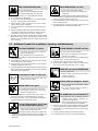
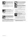
1-3. Additional Symbols for Installation, Operation, and Maintenance
FALLING EQUIPMENT can injure.
D Use handle and have person of adequate
physical strength lift unit.
D Move unit with hand cart or similar device.
D For units without a handle, use equipment of adequate capacity to
lift and support unit.
D Keep equipment (cables and cords) away from moving vehicles
when working from an aerial location.
D If using lift forks to move unit, be sure forks are long enough to
extend beyond opposite side of unit.
D Follow the guidelines in the Applications Manual for the Revised
NIOSH Lifting Equation (Publication No. 94−110) when manually
lifting heavy parts or equipment.
FLYING METAL OR DIRT can injure eyes.
D Wear approved safety glasses with side
shields or wear face shield.
MOVING PARTS can injure.
D Keep away from moving parts such as fans.
D Keep all doors, panels, covers, and guards
closed and securely in place.
D Have only qualified persons remove doors, panels, covers, or
guards for maintenance and troubleshooting as necessary.
D Reinstall doors, panels, covers, or guards when maintenance is
finished and before reconnecting input power.
ELECTRIC AND MAGNETIC FIELDS (EMF
)
can affect Implanted Medical Devices.
D Wearers of Pacemakers and other Implanted
Medical Devices should keep away.
D Implanted Medical Device wearers should consult their docto
r
and the device manufacturer before going near arc welding, spo
t
welding, gouging, plasma arc cutting, or induction heating
operations.
STEAM AND HOT COOLANT can burn.
Hose may rupture if coolant overheats.
D Never disconnect both ends of hose when in-
stalled on hot workpiece.
D If coolant flow stops, leave one end of hose connected to allow
coolant to return to cooler and relieve pressure.
D Remove hose from hot workpiece to prevent damage.
D Visually inspect condition of hoses, cords, and cables before
each use. Do not use damaged hoses, cords, or cables.
OVERUSE can cause OVERHEATING
D Allow cooling period.
D Reduce output or reduce duty cycle before
starting to heat again.
D Follow rated duty cycle.
STATIC (ESD) can damage PC boards.
D Put on grounded wrist strap BEFORE handling
boards or parts.
D Use proper static-proof bags and boxes to
store, move, or ship PC boards.
H.F. RADIATION can cause interference.
D High-frequency (H.F.) can interfere with radio
navigation, safety services, computers, and
communications equipment.
D Have only qualified person familiar with elec-
tronic equipment perform this installation.
D The user is responsible for having a qualified electrician promptly
correct any interference problem resulting from the installation.
D If notified by the FCC about interference, stop using the equip-
ment at once.
D Have the installation regularly checked and maintained.
D Keep high-frequency source doors and panels tightly shut.

OM-222166 Page 3
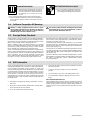
READ INSTRUCTIONS.
D Read and follow all labels and the Owner’s
Manual carefully before installing, operating, or
servicing unit. Read the safety information at
the beginning of the manual and in each
section.
D Use only genuine replacement parts from the manufacturer.
D Perform installation, maintenance, and service according to the
Owner’s Manuals, industry standards, and national, state, and
local codes.
BATTERY EXPLOSION can injure.
D Do not use induction equipment to charge bat-
teries or jump start vehicles unless it has a bat-
tery charging feature designed for this purpose.
1-4. California Proposition 65 Warnings
Welding or cutting equipment produces fumes or gases
which contain chemicals known to the State of California to
cause birth defects and, in some cases, cancer. (California
Health & Safety Code Section 25249.5 et seq.)
This product contains chemicals, including lead, known to the
state of California to cause cancer, birth defects, or other re-
productive harm. Wash hands after use.
1-5. Principal Safety Standards
Safety in Welding, Cutting, and Allied Processes, ANSI Standard Z49.1,
is available as a free download from the American Welding Society at
http://www.aws.org or purchased from Global Engineering Documents
(phone: 1-877-413-5184, website: www.global.ihs.com).
Safety in Welding, Cutting, and Allied Processes, CSA Standard
W117.2, from Canadian Standards Association, Standards Sales, 5060
Spectrum Way, Suite 100, Mississauga, Ontario, Canada L4W 5NS
(phone: 800-463-6727, website: www.csa-international.org).
OSHA, Occupational Safety and Health Standards for General Industry,
Title 29, Code of Federal Regulations (CFR), Part 1910, Subpart Q, and
Part 1926, Subpart J, from U.S. Government Printing Office, Superinten-
dent of Documents, P.O. Box 371954, Pittsburgh, PA 15250-7954
(phone: 1-866-512-1800) (there are 10 OSHA Regional Offices—phone
for Region 5, Chicago, is 312-353-2220, website: www.osha.gov).
National Electrical Code, NFPA Standard 70, from National Fire Protec-
tion Association, Quincy, MA 02269 (phone: 1-800-344-3555, website:
www.nfpa.org and www. sparky.org).
Canadian Electrical Code Part 1, CSA Standard C22.1, from Canadian
Standards Association, Standards Sales, 5060 Spectrum Way, Suite
100, Mississauga, Ontario, Canada L4W 5NS (phone: 800-463-6727,
website: www.csagroup.org).
Safe Practice For Occupational And Educational Eye And Face Protec-
tion, ANSI Standard Z87.1, from American National Standards Institute,
25 West 43rd Street, New York, NY 10036 (phone: 212-642-4900, web-
site: www.ansi.org).
Applications Manual for the Revised NIOSH Lifting Equation, The Na-
tional Institute for Occupational Safety and Health (NIOSH), 1600 Clifton
Rd, Atlanta, GA 30329-4027 (phone: 1-800-232-4636, website:
www.cdc.gov/NIOSH).
1-6. EMF Information
Electric current flowing through any conductor causes localized electric
and magnetic fields (EMF). The current from arc welding (and allied pro-
cesses including spot welding, gouging, plasma arc cutting, and
induction heating operations) creates an EMF field around the welding
circuit. EMF fields can interfere with some medical implants, e.g. pace-
makers. Protective measures for persons wearing medical implants
have to be taken. For example, restrict access for passers−by or con-
duct individual risk assessment for welders. All welders should use the
following procedures in order to minimize exposure to EMF fields from
the welding circuit:
1. Keep cables close together by twisting or taping them, or using a
cable cover.
2. Do not place your body between welding cables. Arrange cables
to one side and away from the operator.
3. Do not coil or drape cables around your body.
4. Keep head and trunk as far away from the equipment in the weld-
ing circuit as possible.
5. Connect work clamp to workpiece as close to the weld as
possible.
6. Do not work next to, sit or lean on the welding power source.
7. Do not weld whilst carrying the welding power source or wire
feeder.
About Implanted Medical Devices:
Implanted Medical Device wearers should consult their doctor and the
device manufacturer before performing or going near arc welding, spot
welding, gouging, plasma arc cutting, or induction heating operations. If
cleared by your doctor, then following the above procedures is recom-
mended.

OM-222166 Page 4
SECTION 2 − CONSIGNES DE SÉCURITÉ − LIRE AVANT
UTILISATION
ihom 2015−09fre
Pour écarter les risques de blessure pour vous−même et pour autrui — lire, appliquer et ranger en lieu sûr ces consignes relatives
aux précautions de sécurité et au mode opératoire.
2-1. Signification des symboles
DANGER! − Indique une situation dangereuse qui si on
l’évite pas peut donner la mort ou des blessures graves.
Les dangers possibles sont montrés par les symboles
joints ou sont expliqués dans le texte.
Indique une situation dangereuse qui si on l’évite pas
peut donner la mort ou des blessures graves. Les
dangers possibles sont montrés par les symboles
joints ou sont expliqués dans le texte.
AVIS − Indique des déclarations pas en relation avec des blessures per-
sonnelles.
. Indique des instructions spécifiques.
Ce groupe de symboles veut dire Avertissement! Attention! DANGER
DE CHOC ELECTRIQUE, PIECES EN MOUVEMENT, et PIECES
CHAUDES. Consulter les symboles et les instructions ci-dessous y
afférant pour les actions nécessaires afin d’éviter le danger.
2-2. Dangers relatifs au soudage à l’arc
Les symboles présentés ci-après sont utilisés tout au long du
présent manuel pour attirer votre attention et identifier les ris-
ques de danger. Lorsque vous voyez un symbole, soyez
vigilant et suivez les directives mentionnées afin d’éviter tout
danger. Les consignes de sécurité présentées ci-après ne font
que résumer l’information contenue dans les normes de sécu-
rité énumérées à la section 2-5. Veuillez lire et respecter toutes
ces normes de sécurité.
L’installation, l’utilisation, l’entretien et les réparations ne
doivent être confiés qu’à des personnes qualifiées.
Au cours de l’utilisation, tenir toute personne à l’écart et plus
particulièrement les enfants.
UNE DÉCHARGE ÉLECTRIQUE peut
entraîner la mort.
Le contact de composants électriques peut
provoquer des accidents mortels ou des brûlures
graves. Le circuit électrique et les barres collectrices
ou les connexions de sortie sont sous tension
lorsque l’appareil fonctionne. Le circuit d’alimentation et les circuits
internes de la machine sont également sous tension lorsque
l’alimentation est sur marche. Des équipements installés ou reliés à la
borne de terre de manière incorrecte sont dangereux.
D Ne pas toucher aux pièces électriques sous tension.
D Protéger toutes les barres collectrices et les raccords de refroidis-
sement pour éviter de les toucher par inadvertance.
D Porter des gants isolants et des vêtements de protection secs et
sans trous.
D S’isoler de la pièce à couper et du sol en utilisant des housses ou
des tapis assez grands afin d’éviter tout contact physique avec la
pièce à couper ou le sol.
D D’autres consignes de sécurité sont nécessaires dans les condi-
tions suivantes : risques électriques dans un environnement
humide ou si l’on porte des vêtements mouillés ; sur des structures
métalliques telles que sols, grilles ou échafaudages ; en position
coincée comme assise, à genoux ou couchée ; ou s’il y a un risque
élevé de contact inévitable ou accidentel avec la pièce à souder ou
le sol. Dans ces conditions, voir ANSI Z49.1 énuméré dans les nor-
mes de sécurité. En outre, ne pas travailler seul !
D Couper l’alimentation d’entrée avant d’installer l’appareil ou d’effec-
tuer l’entretien. Verrouiller ou étiqueter la sortie d’alimentation selon
la norme OSHA 29 CFR 1910.147(se reporter aux Principales nor-
mes de sécurité).
D N’utiliser que des tuyaux de refroidissement non conducteurs ayant
une longueur minimale de 457 mm pour garantir l’isolation.
D Installer le poste correctement et le mettre à la terre convenable-
ment selon les consignes du manuel de l’opérateur et les normes
nationales, provinciales et locales.
D Toujours vérifier la terre du cordon d’alimentation. Vérifier et s’assu-
rer que le fil de terre du cordon d’alimentation est bien raccordé à la
borne de terre du sectionneur ou que la fiche du cordon est raccor-
dée à une prise correctement mise à la terre.
D En effectuant les raccordements d’entrée, fixer d’abord le conduc-
teur de mise à la terre approprié et revérifier les connexions.
D Les câbles doivent être exempts d’humidité, d’huile et de graisse;
protégez−les contre les étincelles et les pièces métalliques chau-
des.
D Vérifier fréquemment le cordon d’alimentation et le conducteur de
mise à la terre afin de s’assurer qu’il n’est pas altéré ou dénudé. Le
remplacer immédiatement s’il l’est. Un fil dénudé peut entraîner la
mort.
D L’équipement doit être hors tension lorsqu’il n’est pas utilisé.
D Ne pas utiliser des câbles usés, endommagés, de grosseur insuffi-
sante ou mal épissés.
D Ne pas enrouler les câbles autour du corps.
D Ne pas toucher le circuit électrique si l’on est en contact avec la piè-
ce, la terre ou le circuit électrique d’une autre machine.
D N’utiliser qu’un matériel en bon état. Réparer ou remplacer sur-le-
champ les pièces endommagées. Entretenir l’appareil conformé-
ment à ce manuel.
D Porter un harnais de sécurité si l’on doit travailler au-dessus du sol.
D S’assurer que tous les panneaux et couvercles sont correctement
en place.
D Utiliser une protection différentielle lors de l’utilisation d’un équi-
pement auxiliaire dans des endroits humides ou mouillés.
Il reste une TENSION DC NON NÉGLIGEABLE dans
les sources de soudage onduleur UNE FOIS le
moteur coupé.
D Avant de toucher des organes internes, couper l’onduleur,
débrancher l’alimentation et décharger les condensateurs
d’alimentation conformément aux instructions indiquées dans la
partie maintenance.
LES FUMÉES ET LES GAZ peuvent
être dangereux.
Le chauffage à induction de certains matériaux
,
adhésifs et flux génère des fumées et des gaz. Leur
inhalation peut être dangereuse pour votre santé.
D Ne pas mettre sa tête au-dessus des vapeurs. Ne pas respirer ces
vapeurs.
D À l’intérieur, ventiler la zone et/ou utiliser une ventilation forcée au
niveau de l’arc pour l’évacuation des fumées et des gaz. Pour dé-
terminer la bonne ventilation, il est recommandé de procéder à un
prélèvement pour la composition et la quantité de fumées et de gaz
auxquels est exposé le personnel.
D Si la ventilation est médiocre, porter un respirateur anti-vapeurs ap-
prouvé.
D Lire et comprendre les fiches de données de sécurité et les instructions
du fabricant concernant les adhésifs, les revêtements, les nettoyants,

OM-222166 Page 5
les consommables, les produits de refroidissement, les dégraisseurs,
les flux et les métaux.
D Travailler dans un espace fermé seulement s’il est bien ventilé ou en
portant un respirateur. Demander toujours à un surveillant dûment
formé de se tenir à proximité. Des fumées et des gaz provenant du
chauffage peuvent déplacer l’air, abaisser le niveau d’oxygène et
provoquer des lésions ou des accidents mortels. S’assurer que l’air
ambiant ne présente aucun danger.
D Ne pas chauffer dans des endroits se trouvant à proximité d’opéra-
tions de dégraissage, de nettoyage ou de pulvérisation. La chaleur
peut réagir en présence de vapeurs et former des gaz hautement
toxiques et irritants.
D Ne pas surchauffer des métaux munis d’un revêtement tels que l’acier
galvanisé, plaqué au plomb ou au cadmium, à moins que le revêtement
ne soit enlevé de la zone chauffée, que la zone soit bien ventilée et, si
nécessaire, en portant un respirateur. Les revêtements et tous les mé-
taux contenant ces éléments peuvent dégager des fumées toxiques
s’ils sont surchauffés. Voir les informations concernant la température
dans les spécifications de revêtement SDS.
Risque D’INCENDIE OU
D’EXPLOSION.
D Ne pas surchauffer les composants .
D Attention aux risques d’incendie: tenir un ex-
tincteur à proximité.
D Stocker des produits inflammables hors de la zone de travail.
D Ne pas placer l’appareil sur, au-dessus ou à proximité de surfaces
inflammables.
D Ne pas installer l’appareil à proximité de produits inflammables.
D Ne pas souder là où l’air ambiant pourrait contenir des poussières,
gaz ou émanations inflammables (vapeur d’essence, par exemple).
D Une fois le travail achevé, assurez−vous qu’il ne reste aucune trace
d’étincelles incandescentes ni de flammes.
D Utiliser exclusivement des fusibles ou coupe−circuits appropriés.
Ne pas augmenter leur puissance; ne pas les ponter.
D Lire et comprendre les fiches de données de sécurité et les instruc-
tions du fabricant concernant les adhésifs, les revêtements, les
nettoyants, les consommables, les produits de refroidissement, les
dégraisseurs, les flux et les métaux.
D Porter un équipement de protection pour le corps fait d’un matériau
résistant et ignifuge (cuir, coton robuste, laine). La protection du
corps comporte des vêtements sans huile comme par ex. des gants
de cuir, une chemise solide, des pantalons sans revers, des
chaussures hautes et une casquette.
LE CHAUFFAGE PAR INDUCTION peut
provoquer des brûlures.
D Ne pas toucher des parties chaudes à mains
nues.
D Laisser refroidir les composants ou équipe-
ments avant de les manipuler.
D Ne pas toucher ou manipuler les câbles/enroulements d’induc-
tion durant l’opération à moins que l’équipement soit conçu à cet
effet comme indiqué dans le manuel d’utilisateur.
D Tenir les bijoux et autres objets personnels en métal éloignés de la
tête/de l’enroulement pendant le fonctionnement.
D Ne pas toucher aux pièces chaudes, utiliser les outils recom-
mandés et porter des gants de soudage et des vêtements épais
pour éviter les brûlures.
2-3. Dangers supplémentaires en relation avec l’installation, le fonctionnement et l
a
maintenance
LA CHUTE DE L’ÉQUIPEMENT peut
provoquer des blessures.
D Utiliser la poignée et demander à une personne
ayant la force physique nécessaire pour soule-
ver l’appareil.
D Déplacer l’appareil à l’aide d’un chariot ou d’un engin similaire.
D Pour les unités sans poignée, utiliser un équipement de levage de
capacité suffisante pour lever l’appareil.
D Tenir l’équipement (câbles et cordons) à distance des véhicules
mobiles lors de toute opération en hauteur.
D En utilisant des fourches de levage pour déplacer l’unité, s’assu-
rer que les fourches sont suffisamment longues pour dépasser du
côté opposé de l’appareil.
D Suivre les consignes du Manuel des applications pour l’équation
de levage NIOSH révisée (Publication Nº94−110) lors du levage
manuelle de pièces ou équipements lourds.
DES PIECES DE METAL ou DES
SALETES peuvent provoquer des
blessures dans les yeux.
D Porter des lunettes de sécurité à coques latéra-
les ou un écran facial.
DES ORGANES MOBILES peuvent
provoquer des blessures.
D S’abstenir de toucher des organes mobiles tels
que des ventilateurs.
D Maintenir fermés et verrouillés les portes, panneaux, recouvre-
ments et dispositifs de protection.
Les CHAMPS ÉLECTROMAGNÉTIQUES (CEM)
peuvent affecter les implants médicaux.
D Les porteurs de stimulateurs cardiaques et autres
implants médicaux doivent rester à distance.
D Les porteurs d’implants médicaux doivent consulter leur médecin
et le fabricant du dispositif avant de s’approcher de la zone où se
déroule du soudage à l’arc, du soudage par points, du gougeage,
de la découpe plasma ou une opération de chauffage par induction.
LE LIQUIDE DE REFROIDISSEMENT CHAUD ET
LA VAPEUR peuvent causer des brûlures.
Si le liquide de refroidissement est en surchauffe, un
boyau pourrait se sectionner.
D Ne jamais débrancher les deux extrémités du
tuyau lorsque l’appareil est installé sur une
pièce de travail chaude.
D Si le liquide de refroidissement cesse de s’écouler, laisser une
extrémité du tuyau branchée pour permettre au liquide de
refroidissement chaud de revenir au refroidisseur et
dépressuriser.
D Pour éviter tout risque de dommage, retirer le tuyau de la pièce de
travail chaude.
D Effectuer une inspection visuelle des boyaux, cordons et câbles
avant chaque utilisation. Ne pas utiliser des boyaux, cordons ou
câbles endommagés.
L’EMPLOI EXCESSIF peut SUR-
CHAUFFER L’ÉQUIPEMENT.
D Prévoir une période de refroidissement
D Réduire le courant de sortie ou le facteur de mar-
che avant de recommencer le chauffage.
D Respecter le cycle opératoire nominal.

OM-222166 Page 6
LES CHARGES ÉLECTROSTATIQUES
peuvent endommager les circuits im-
primés.
D Établir la connexion avec la barrette de terre
AVANT de manipuler des cartes ou des pièces.
D Utiliser des pochettes et des boîtes antistatiques pour stocker, dé-
placer ou expédier des cartes PC.
LE RAYONNEMENT HAUTE FRÉ-
QUENCE (HF) risque de provoquer
des interférences.
D Le rayonnement haute fréquence (HF) peut
provoquer des interférences avec les équipe-
ments de radio-navigation et de communication,
les services de sécurité et les ordinateurs.
D Demander seulement à des personnes qualifiées familiarisées avec
des équipements électroniques de faire fonctionner l’installation.
D L’utilisateur est tenu de faire corriger rapidement par un électricien
qualifié les interférences résultant de l’installation.
D Si le FCC signale des interférences, arrêter immédiatement l’appa-
reil.
D Effectuer régulièrement le contrôle et l’entretien de l’installation.
D Maintenir soigneusement fermés les portes et les panneaux des
sources de haute fréquence.
LIRE LES INSTRUCTIONS.
D Lire et appliquer les instructions sur les
étiquettes et le Mode d’emploi avant
l’installation, l’utilisation ou l’entretien de
l’appareil. Lire les informations de sécurité au
début du manuel et dans chaque section.
D N’utiliser que les pièces de rechange recommandées par le
constructeur.
D Effectuer l’installation, l’entretien et toute intervention selon les
manuels d’utilisateurs, les normes nationales, provinciales et de
l’industrie, ainsi que les codes municipaux.
L’EXPLOSION DE LA BATTERIE pe
ut
provoquer des blessures.
D Ne pas utiliser l’appareil de soudage pou
r
charger des batteries ou faire démarrer de
s
véhicules à l’aide de câbles de démarrage, sau
f
si l’appareil dispose d’une fonctionnalité d
e
charge de batterie destinée à cet usage.
2-4. Proposition californienne 65 Avertissements
Les équipements de soudage et de coupage produisent des
fumées et des gaz qui contiennent des produits chimiques
dont l’État de Californie reconnaît qu’ils provoquent des
malformations congénitales et, dans certains cas, des cancers.
(Code de santé et de sécurité de Californie, chapitre 25249.5
et suivants).
Ce produit contient des éléments chimiques, dont le plomb,
reconnus par l’État de Californie pour leur caractère
cancérogène ainsi que provoquant des malformations
congénitales ou autres problèmes de procréation. Se laver les
mains après toute manipulation.
2-5. Principales normes de sécurité
Safety in Welding, Cutting, and Allied Processes, ANSI Standard Z49.1,
from Global Engineering Documents (phone: 1-877-413-5184, website:
www.global.ihs.com).
Safety in Welding, Cutting, and Allied Processes, CSA Standard
W117.2, from Canadian Standards Association, Standards Sales, 5060
Spectrum Way, Suite 100, Mississauga, Ontario, Canada L4W 5NS
(phone: 800-463-6727, website: www.csagroup.org).
OSHA, Occupational Safety and Health Standards for General Industry,
Title 29, Code of Federal Regulations (CFR), Part 1910, Subpart Q, and
Part 1926, Subpart J, from U.S. Government Printing Office, Superinten-
dent of Documents, P.O. Box 371954, Pittsburgh, PA 15250-7954
(phone: 1-866-512-1800) (there are 10 OSHA Regional Offices—phone
for Region 5, Chicago, is 312-353-2220, website: www.osha.gov).
National Electrical Code, NFPA Standard 70, from National Fire Protec-
tion Association, Quincy, MA 02269 (phone: 1-800-344-3555, website:
www.nfpa.org and www. sparky.org).
Canadian Electrical Code Part 1, CSA Standard C22.1, from Canadian
Standards Association, Standards Sales, 5060 Spectrum Way, Suite
100, Mississauga, Ontario, Canada L4W 5NS (phone: 800-463-6727,
website: www.csagroup.org).
Safe Practice For Occupational And Educational Eye And Face Protec-
tion, ANSI Standard Z87.1, from American National Standards Institute,
25 West 43rd Street, New York, NY 10036 (phone: 212-642-4900, web-
site: www.ansi.org).
Applications Manual for the Revised NIOSH Lifting Equation, The Na-
tional Institute for Occupational Safety and Health (NIOSH), 1600 Clifton
Rd, Atlanta, GA 30329-4027 (phone: 1-800-232-4636, website:
www.cdc.gov/NIOSH).
2-6. Informations relatives aux CEM
Le courant électrique qui traverse tout conducteur génère des champs
électromagnétiques (CEM) à certains endroits. Le courant issu d’un
soudage à l’arc (et de procédés connexes, y compris le soudage par
points, le gougeage, le découpage plasma et les opérations de
chauffage par induction) crée un champ électromagnétique (CEM)
autour du circuit de soudage. Les champs électromagnétiques produits
peuvent causer interférence à certains implants médicaux, p. ex. les
stimulateurs cardiaques. Des mesures de protection pour les porteurs
d’implants médicaux doivent être prises: Limiter par exemple tout accès
aux passants ou procéder à une évaluation des risques individuels pour
les soudeurs. Tous les soudeurs doivent appliquer les procédures
suivantes pour minimiser l’exposition aux CEM provenant du circuit de
soudage:
1. Rassembler les câbles en les torsadant ou en les attachant avec
du ruban adhésif ou avec une housse.
2. Ne pas se tenir au milieu des câbles de soudage. Disposer les
câbles d’un côté et à distance de l’opérateur.
3. Ne pas courber et ne pas entourer les câbles autour de votre
corps.
4. Maintenir la tête et le torse aussi loin que possible du matériel du
circuit de soudage.
5. Connecter la pince sur la pièce aussi près que possible de la
soudure.
6. Ne pas travailler à proximité d’une source de soudage, ni
s’asseoir ou se pencher dessus.
7. Ne pas souder tout en portant la source de soudage ou le
dévidoir.
En ce qui concerne les implants médicaux :
Les porteurs d’implants doivent d’abord consulter leur médecin avant de
s’approcher des opérations de soudage à l’arc, de soudage par points,
de gougeage, du coupage plasma ou de chauffage par induction. Si le
médecin approuve, il est recommandé de suivre les procédures précé-
dentes.

OM-222166 Page 7
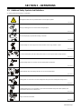
SECTION 3 − DEFINITIONS
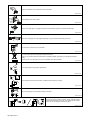
3-1. Additional Safety Symbols And Definitions
. Some symbols are found only on CE products.
Warning! Watch Out! There are possible hazards as shown by the symbols.
Safe1 2012−05
Wear dry insulating gloves. Do not wear wet or damaged gloves.
Safe56 2012−05
Disconnect input plug or power before working on machine.
Safe5 2012−05
Induction heating can cause injury or burns from hot items such as rings, watches, or parts.
Safe74 2012−07
Do not wear metal jewelry and other metal personal items such as rings and watches during operation.
Safe75 2012−07
Induction heating sparks can cause fire. Do not overheat parts and adhesives.
Safe76 2012−07
Keep flammables away from heating operation. Do not heat near flammables.
Safe77 2012−07
Heating sparks can cause fires. Have a fire extinguisher nearby and have a watchperson ready to use it.
Safe78 2012−07
Breathing heating fumes can be hazardous to your health. Read Material Safety Data Sheets (MSDSs) and
manufacturer’s instructions for material used.
Safe79 2012−07
Keep your head out of the fumes.
Safe80 2012−07

OM-222166 Page 8
Use forced ventilation or local exhaust to remove the fumes.
Safe81 2012−07
Use ventilating fan to remove fumes.
Safe82 2012−07
Always wear safety glasses or goggles during and around heating operations to prevent possible injury.
Safe83 2012−07
Wear either safety glasses or full goggles depending on type of operation and nearby processes.
Safe84 2012−07
Do not remove or paint over (cover) the label.
Safe20 2012−05
Do not discard product (where applicable) with general waste.
Reuse or recycle Waste Electrical and Electronic Equipment (WEEE) by disposing at a designated collection
facility.
Contact your local recycling office or your local distributor for further information.
Safe37 2012−05
?
V
?
A
Consult rating label for input power requirements.
Safe34 2012−05
Become trained and read the instructions and labels before working on machine.
Safe35 2012−05
Disconnect input plug or power before working on machine.
Safe30 2012−05
V
V
V
Hazardous voltage remains on input capacitors after power is turned
off. Do not touch fully charged capacitors. Always wait after power is
turned off before working on unit, OR check input capacitor voltage,
and be sure it is near 0 before touching any parts.
Safe42 2012−05

OM-222166 Page 9
Connect green or green/yellow grounding conductor to ground
terminal.
Connect input conductors (L1, L2 And L3) to line terminals.
Safe86 2012−06
Become trained and read the instructions before working on the
machine or heating.
Safe85 2012−06
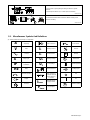
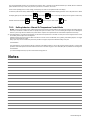
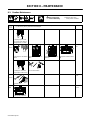
3-2. Miscellaneous Symbols And Definitions
. Some symbols are found only on CE products.
A
Amperage
V
Volts
Alternating
Current
X
Duty Cycle
IP
Degree Of
Protection
Hz
Hertz
Circuit Protection
Output
Increase
Line Connection
I
1
Primary Current
I
2
Rated Current
U
1
Primary Voltage
U
2
Load Voltage
Read Instructions
Three Phase
Static Frequency
Converter-Transfo
rmer-Frequency
Converter
I
1max
Rated Maximum
Supply Current
P
1max
Maximum Power
Consumption
Three Phase
Percent
Remote
Panel/Local
High Temperature
Voltage Input
Off
On
Induction Heating

OM-222166 Page 10
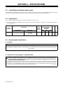
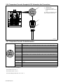
SECTION 4 − SPECIFICATIONS
4-1. Serial Number and Rating Label Location
The serial number and rating information for the power source is located on the front of the machine. Use the rating labels to determine input power
requirements and/or rated output. For future reference, write serial number in space provided on back cover of this manual.
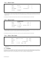
4-2. Specifications
. This equipment will deliver rated output at an ambient air temperature up to 104F ( 40C).
. Do not use information in unit specifications table to determine electrical service requirements. See Sections 5-3, 5-4 and 5-5 for information on
connecting input power.
Output
Frequency
Rated Output
Required
Reflective
Inductanc
e
Amperes Input at
Rated Load Output
50 or 60 Hz,
Three-Phase
Single Output Dual Output 400 V 460 V 575 V
kVA kW
5 To 30 kHz
35 kW At 100% Duty Cycle
350 A (RMS), 700 V (RMS)
35 kW At 100% Duty Cycle
700 A (RMS),
700 V (RMS)
2.5 To 50
μh
60 A 50 A 40 A 39 37
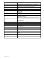
4-3. Environmental Specifications
A. IP Rating
IP Rating
IP23C
This equipment is designed for outdoor use. It may be stored, but is not intended to be used for welding (heating) outside during precipitation
unless sheltered.
Ref. IP23 2014−06
B. Information On Electromagnetic Compatibility (EMC)
! This Class A equipment is not intended for use in residential locations where the electrical power is provided by the public low−
voltage supply system. There may be potential difficulties in ensuring electromagnetic compatibility in those locations, due to
conducted as well as radiated disturbances.
This equipment complies with IEC61000-3-11 and IEC 61000−3−12 and can be connected to public low-voltage systems provided that the public
low-voltage system impedance Z
max
at the point of common coupling is less than 33.37mW (or the short−circuit power S
sc
is greater than
4,795,346 VA). It is the responsibility of the installer or user of the equipment to ensure, by consultation with the distribution network operator
if necessary, that the system impedance complies with the impedance restrictions.
ce-emc 1 2014-07

OM-222166 Page 11
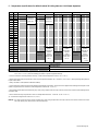
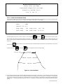
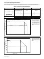
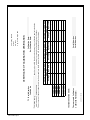
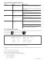
C. Temperature Specifications For Miller ProHeat 35 Rolling Inductor Cold Climate Operation
ProHeat Cooler Rolling Inductor Heating Cables
°C °F Storage Operation Storage Operation Storage Operation Storage Operation
60 140
Reduced
efficiencies
above 40°C
Reduced
efficiencies
above 40°C
55 131
50 122
45 113
40 104
35 95
30 86
25 77
20 68
15 59
10 50
5 41
0 32
−5 23
−10 14
−15 5
Energize
system
frequently to
maintain
coolant
temperature
above 14°F
(−10°C).
Energize
system
frequently to
maintain
coolant
temperature
above 14°F
(−10°C).
Energize
system
frequently to
maintain
coolant
temperature
above 14°F
(−10°C).
−20 -4
−25 -13
Store dry Store dry Store dry
−30 -22
−35 -31
−40 -40
277088-A
Not Recommended
With Qualifications
Normal Operation With Coolant
NOTICE − The Miller ProHeat 35 Rolling Inductor is rated for operation between 14° F and 140° F (−10° C to 60° C). For operation at -40° F to
14° F (−40° C to -10° C), take the following precautions to prevent equipment damage:
• Connect coolant lines to Rolling Inductor when dry, or when ambient temperature is above −4° F (−20° C).
• Operate ProHeat 35 Heavy Duty Induction Cooler only in temperatures between 14° F and 104° F (−10° C to 40° C) while operating Rolling Inductor/
Liquid Cooled Cables.
• Always use Miller Coolant (Miller Part Number 043810).
• Coolant must flow continuously through the Rolling Inductor/liquid cooled cables, and power must be applied to the Rolling Inductor /liquid cooled
cables at regular intervals to maintain a coolant temperature of at least 14° F (−10° C).
• Store Rolling Inductor/liquid cooled cables dry. Dry unit by using compressed air at 40 psi (2.75 bar) max to blow coolant out of the Rolling Inductor
and power cable.
• Store ProHeat 35 Heavy Duty Induction Cooler at a temperature between−4° F and 131° F(−20° C to 55° C).
. Coolant will not begin to flow until it is 14° F (−10° C).
NOTICE − For colder storage, the cooler must be stored dry. Dry unit by using compressed air at 40 psi (2.75 bar) max to blow coolant out of coolant
lines, filter bowls, pump, flow indicator, and heat exchanger.

OM-222166 Page 12
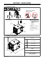
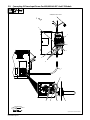
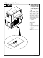
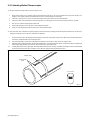
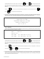
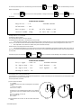
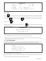
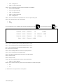
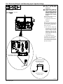
SECTION 5 − INSTALLATION
! Special installation may be
required where gasoline or
volatile liquids are present −
see NEC Article 511 or CEC
Section 20.
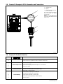
1 Lifting Eye
2 Lifting Forks
Use lifting eye or lifting forks to
move unit.
If using lifting forks, extend forks
beyond opposite side of unit.
3 Line Disconnect Device
Locate unit near correct input
power supply.
5-1. Selecting A Location
3
18 in.
(460 mm)
18 in.
(460 mm)
OR
1
2
Movement
Location And Airflow
loc_large 2015-04
! Do not move or operate unit
where it could tip.
803992-B
18 in.
(460 mm)
18 in.
(460 mm)
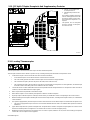
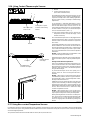
5-2. Dimensions And Weights
803 992-B
B
C
A
*
Dimensions
A
27.5 in. (699 mm)
B 21.75 in. (553 mm)
C 36.75 in. (933 mm)
Weight
227 lb (103 Kg)
* Lifting Eye Weight Rating
600 lb (272 kg) Maximum

OM-222166 Page 13
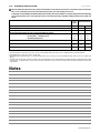
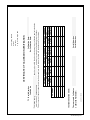
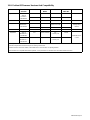
5-3. Electrical Service Guide
Elec Serv 2014−01
Failure to follow these electrical service guide recommendations could create an electric shock or fire hazard. These recommenda-
tions are for a dedicated circuit sized for the rated output and duty cycle of the welding power source.
In dedicated circuit installations, the National Electrical Code (NEC) allows the receptacle or conductor rating to be less than the rating
of the circuit protection device. All components of the circuit must be physically compatible. See NEC articles 210.21, 630.11, and
630.12.
50 Hz
Three
Phase
60 Hz Three Phase
Input Voltage (V) 400 460 575
Input Amperes (A) At Rated Output 60 50 40
Input Amperes (A) At Rated Output 60 50 40
Max Recommended Standard Fuse Or Circuit Breaker Rating In Amperes
1
Circuit Breaker
1
, Time-Delay Fuses
2
70 61 45
Normal Operating Fuses
3
80 70 60
Min Input Conductor Size In AWG
4
6 8 8
Max Recommended Input Conductor Length In Feet (Meters)
254
(77)
214
(65)
334
(102)
Min Grounding Conductor Size In AWG
4
8 8 10
Reference: 2014 National Electrical Code (NEC) (including article 630)
1 If a circuit breaker is used in place of a fuse, choose a circuit breaker with time-current curves comparable to the recommended fuse.
2 “Time-Delay” fuses are UL class “RK5” . See UL 248.
3 “Normal Operating” (general purpose - no intentional delay) fuses are UL class “K5” (up to and including 60 amps), and UL class “H” ( 65 amps and
above).
4 Conductor data in this section specifies conductor size (excluding flexible cord or cable) between the panelboard and the equipment per NEC Table
310.15(B)(16). If a flexible cord or cable is used, minimum conductor size may increase. See NEC Table 400.5(A) for flexible cord and cable
requirements.
Notes

OM-222166 Page 14
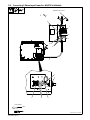
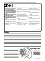
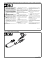
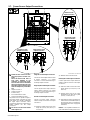
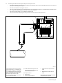
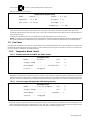
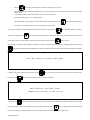
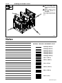
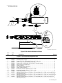
5-4. Connecting 3-Phase Input Power For 460/575 Volt Models
3/8 in.
Tools Needed:
2
1
4
365
7
10
8
4
9
6
3
input3 2015−01 / 803 994-D
GND/PE Earth Ground
La page est en cours de chargement...
La page est en cours de chargement...
La page est en cours de chargement...
La page est en cours de chargement...
La page est en cours de chargement...
La page est en cours de chargement...
La page est en cours de chargement...
La page est en cours de chargement...
La page est en cours de chargement...
La page est en cours de chargement...
La page est en cours de chargement...
La page est en cours de chargement...
La page est en cours de chargement...
La page est en cours de chargement...
La page est en cours de chargement...
La page est en cours de chargement...
La page est en cours de chargement...
La page est en cours de chargement...
La page est en cours de chargement...
La page est en cours de chargement...
La page est en cours de chargement...
La page est en cours de chargement...
La page est en cours de chargement...
La page est en cours de chargement...
La page est en cours de chargement...
La page est en cours de chargement...
La page est en cours de chargement...
La page est en cours de chargement...
La page est en cours de chargement...
La page est en cours de chargement...
La page est en cours de chargement...
La page est en cours de chargement...
La page est en cours de chargement...
La page est en cours de chargement...
La page est en cours de chargement...
La page est en cours de chargement...
La page est en cours de chargement...
La page est en cours de chargement...
La page est en cours de chargement...
La page est en cours de chargement...
La page est en cours de chargement...
La page est en cours de chargement...
La page est en cours de chargement...
La page est en cours de chargement...
La page est en cours de chargement...
La page est en cours de chargement...
La page est en cours de chargement...
La page est en cours de chargement...
La page est en cours de chargement...
La page est en cours de chargement...
La page est en cours de chargement...
La page est en cours de chargement...
La page est en cours de chargement...
La page est en cours de chargement...
La page est en cours de chargement...
La page est en cours de chargement...
La page est en cours de chargement...
La page est en cours de chargement...
La page est en cours de chargement...
La page est en cours de chargement...
La page est en cours de chargement...
La page est en cours de chargement...
La page est en cours de chargement...
La page est en cours de chargement...
La page est en cours de chargement...
La page est en cours de chargement...
La page est en cours de chargement...
La page est en cours de chargement...
La page est en cours de chargement...
La page est en cours de chargement...
La page est en cours de chargement...
La page est en cours de chargement...
La page est en cours de chargement...
La page est en cours de chargement...
La page est en cours de chargement...
La page est en cours de chargement...
La page est en cours de chargement...
La page est en cours de chargement...
-
 1
1
-
 2
2
-
 3
3
-
 4
4
-
 5
5
-
 6
6
-
 7
7
-
 8
8
-
 9
9
-
 10
10
-
 11
11
-
 12
12
-
 13
13
-
 14
14
-
 15
15
-
 16
16
-
 17
17
-
 18
18
-
 19
19
-
 20
20
-
 21
21
-
 22
22
-
 23
23
-
 24
24
-
 25
25
-
 26
26
-
 27
27
-
 28
28
-
 29
29
-
 30
30
-
 31
31
-
 32
32
-
 33
33
-
 34
34
-
 35
35
-
 36
36
-
 37
37
-
 38
38
-
 39
39
-
 40
40
-
 41
41
-
 42
42
-
 43
43
-
 44
44
-
 45
45
-
 46
46
-
 47
47
-
 48
48
-
 49
49
-
 50
50
-
 51
51
-
 52
52
-
 53
53
-
 54
54
-
 55
55
-
 56
56
-
 57
57
-
 58
58
-
 59
59
-
 60
60
-
 61
61
-
 62
62
-
 63
63
-
 64
64
-
 65
65
-
 66
66
-
 67
67
-
 68
68
-
 69
69
-
 70
70
-
 71
71
-
 72
72
-
 73
73
-
 74
74
-
 75
75
-
 76
76
-
 77
77
-
 78
78
-
 79
79
-
 80
80
-
 81
81
-
 82
82
-
 83
83
-
 84
84
-
 85
85
-
 86
86
-
 87
87
-
 88
88
-
 89
89
-
 90
90
-
 91
91
-
 92
92
-
 93
93
-
 94
94
-
 95
95
-
 96
96
-
 97
97
-
 98
98


Miller MH030157G Le manuel du propriétaire
- Catégorie
- Système de soudage
- Taper
- Le manuel du propriétaire
- Ce manuel convient également à
dans d''autres langues
- English: Miller MH030157G Owner's manual
Documents connexes
-
Miller PROHEAT 35 CE 907271, 907298, 907432 Le manuel du propriétaire
-
-
Miller MC490011G Le manuel du propriétaire
-
-
-
-
-
-
-