KitchenAid YKDRP707RS00 Guide d'installation
- Taper
- Guide d'installation

I_itchenAid _
INSTALLATION INSTRUCTIONS
30" (76.2 CM) AND 36" (91.4 CM)
CLASSIC COMMERCIAL STYLE DUAL FUEL
CONVECTION RANGE WITH STEAM-ASSIST
INSTRUCTIONS DINSTALLATION
CUISINIERE A CONVECTION DE 30" (76,2 CM) ET36"
(91,4 CM)- STYLE CLASSIQUE COMMERCIAL A
BI-COMBUSTIBLE AVEC INJECTION DE VAPEUR
Table of Contents/Table des matieres ............................................................................. 2
Models/ModUles YKDRP707 YKDRP767
9762871

TABLEOF CONTENTS
RANGE SAFETY ............................................................................. 3
INSTALLATION REQUIREMENTS ................................................ 4
Tools and Parts ............................................................................ 4
Location Requirements ................................................................ 4
Electrical Requirements ............................................................... 7
Gas Supply Requirements ........................................................... 7
INSTALLATION INSTRUCTIONS .................................................. 9
Unpack Range .............................................................................. 9
Level Range .................................................................................. 9
Install Anti-Tip Bracket ................................................................. 9
Attach Backguard or Island Trim ............................................... 10
Make Gas Connection ............................................................... 10
Electronic Ignition System ......................................................... 11
Reinstall Bottom Vent ................................................................ 12
Complete Installation ................................................................. 12
WIRING DIAGRAMS ..................................................................... 13
TABLE DES MATIERES
S¢:CURITI:!:DE LA CUISINIERE ................................................... 15
EXIGENCES D'INSTALLATION ................................................... 16
Outillage et pieces ...................................................................... 16
Exigences d'emplacement ......................................................... 16
Specifications de I'installation electrique .................................. 19
Specifications de I'alimentation en gaz ..................................... 19
INSTRUCTIONS D'INSTALLATION ............................................. 21
D_ballage de la cuisiniere .......................................................... 21
Reglage de I'aplomb de la cuisiniere ......................................... 21
Installation de la bride antibasculement .................................... 21
Fixation du dosseret ou de la garniture en riot .......................... 22
Raccordement a la canalisation de gaz ..................................... 23
Systeme d'allumage electronique .............................................. 24
Reinstallation de I'event du fond ................................................ 25
Achever I'installation .................................................................. 25
SCHEMAS DE CABLAGE ............................................................ 26
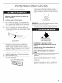
IMPORTANT:
Installer: Leave installation instructions with the homeowner.
Homeowner: Keep installation instructions for future reference.
Save installation instructions for local electrical inspector's use.
IMPORTANT :
Installateur : Remettre les instructions d'installation au proprietaire.
Proprietaire : Conserver les instructions d'installation pour reference ulterieure.
Conserver les instructions d'installation pour consultation par I'inspecteur local des installations electriques.

RANGE SAFETY
Your safety and the safety of others are very important.
We have provided many important safety messages in this manual and on your appliance. Always read and obey all safety
messages.
This is the safety alert symbol.
This symbol alerts you to potential hazards that can kill or hurt you and others.
All safety messages will follow the safety alert symbol and either the word "DANGER" or "WARNING."
These words mean:
You can be killed or seriously injured if you don't immediately
follow instructions.
You can be killed or seriously injured if you don't follow
instructions.
All safety messages will tell you what the potential hazard is, tell you how to reduce the chance of injury, and tell you what can
happen if the instructions are not followed.
I WARNING: If the information in this manual is not followed exactly, a fire or explosion I
I
may result causing property damage, personal injury or death,
I
- Do not store or use gasoline or other flammable vapors and liquids in the vicinity of this
or any other appliance.
m WHAT TO DO IF YOU SMELL GAS:
• Do not try to light any appliance.
• Do not touch any electrical switch.
• Do not use any phone in your building.
• Immediately call your gas supplier from a neighbor's phone. Follow the gas supplier's
instructions.
• If you cannot reach your gas supplier, call the fire department.
- Installation and service must be performed by a qualified installer, service agency or
the gas supplier.
Tip Over Hazard
A child or adult can tip the range and be killed.
Connect anti-tip bracket to wall behind range.
Reconnect the anti-tip bracket, if the range is moved.
Failure to follow these instructions can result in death or serious burns to children and adults.

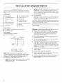
IN STALLATION REQUIREMENTS
• Island trim and attachment screws (3).
Gather the required tools and parts before starting installation.
Read and follow the instructions provided with any tools listed
here.
Tools needed
• Tape measure • 1¾6"combination wrench
• Flat-blade screwdriver • Marker or pencil
• Phillips screwdriver • Masking tape
• Level • Pipe-joint compound
resistant to LP gas
• Hand or electric drill
• Channel lock pliers • Noncorrosive leak-detection
solution
• Pipe wrench
• Stud finder
NOTE: The island trim included with the range may be used if
installed with 1" (2.5 cm) clearance on the 30" (76.2 cm)
model or 5" (12.7 cm) clearance on the 36" (91.4 cm) model
from a combustible rear wall or with 0" (0 cm) clearance from
a noncombustible rear wall,
• LP conversion kit.
NOTE: The cooktop is manufactured for use with Natural gas.
To convert to LP gas, see the gas conversion instructions
provided in the literature package.
Check local codes and consult gas supplier. Check existing gas
supply and electrical supply. See "Electrical Requirements" and
"Gas Supply Requirements" sections.
All electrical connections should be made by a licensed, qualified
electrical installer.
Parts needed
• A UL listed or CSA approved conduit connector
• ULlisted wire nuts
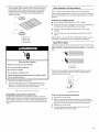
Parts supplied
Check that all parts are included.
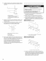
• Anti-tip bracket kit
1"
A(2.5 cm)'--1Ii_ I_¢/-" I (4.4cl__ )
C
A. Anti-tip bracket - 1" (2.5 cm)
B.Anti-tip bracket - 13/4"(4.4 cm)
C. #!0 x 2" Phillips head screws (2)
NOTE: Brackets must be securely attached to wall stud.
Thickness of finished wall may require longer screws to anchor
bracket to wall. Longer screws are available from your local
hardware store. See "Install Anti-Tip Bracket" section.
• Backguard and attachment screws (7).
NOTE: The backguard included with the range is required if
installed with less than 1" (2,5 cm) clearance from a
combustible rear wall.
IMPORTANT." Observe allgoverningcodes and ordinances.Do
not obstruct flow of combustion and ventilation air.
• It is the installer's responsibility to comply with installation
clearances specified on the model/serial rating plate. The
model/serial rating plate is located on the right vertical
surface of the oven door frame.
• It is recommended that a 600 CFM or larger range hood be
installed above the range.
• Recessed installations must provide complete enclosure of
the sides and rear of the range.
To eliminate the risk of burns or fire by reaching over heated
surface units, cabinet storage space located above the
surface units should be avoided. If cabinet storage is to be
provided, the risk can be reduced by installing a range hood
that projects horizontally a minimum of 5" (12.7 cm) beyond
the bottom of the cabinets.
• All openings in the wall or floor where range is to be installed
must be sealed.
• Do not seal the range to the side cabinets.
• Cabinet opening dimensions that are shown must be used.
Given dimensions are minimum clearances.
• The wall anti-tip bracket must be installed. To install the anti-
tip bracket shipped with the range, see "Install Anti-Tip
Bracket" section.

• Groundedelectricalsupplyisrequired.See"Electrical
Requirements"section.
• Propergassupplyconnectionmustbeavailable.See"Gas
SupplyRequirements"section.
Contactaqualifiedfloorcoveringinstallertocheckthatthe
floorcoveringcanwithstandatleast200°F(93°C).Usean
insulatedpador1A"(0.64cm)plywoodovercarpetandunder
rangeifinstallingrangeovercarpeting.
iMPORTANT:Somecabinetandbuildingmaterialsarenot
designedtowithstandtheheatproducedbytheovenforbaking
andself-cleaning.Checkwithyourbuilderorcabinetsupplierto
makesurethatthematerialsusedwillnotdiscolor,delaminateor
sustainotherdamage.
Mobile Home - Additional Installation Requirements
The installation of this range must conform to the Manufactured
Home Construction and Safety Standard, Title 24 CFR, Part 3280
(formerly the Federal Standard for Mobile Home Construction
and Safety, Title 24, HUD Part 280). When such standard is not
applicable, use the Standard for Manufactured Home
Installations, ANSI A225.1/NFPA 501A or with local codes.
In Canada, the installation of this range must conform with the
current standards CAN/CSA-A240-1atest edition, or local codes.
Mobile home installations require:
• When this range is installed in a mobile home, it must be
secured to the floor during transit. Any method of securing
the range is adequate as long as it conforms to the standards
listed above.
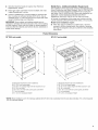
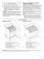
Product Dimensions
30" (76.2 cm) models 36" (91.7 cm) models]
G G
f
B
B
\
A. Backguard (required for some installations)
B.45" (114.3 cm) overall height
C. 36" (91.4 cm) cooktep height with feet loosened 3/4turn
D. 30" (76.2 cm) width
E. 26_/2'' (67.3 crn) width with control panel, see NOTE*
F. Y4"(6.4 cm) spacer
G. 9¼" (23.5 cm) backguard height
A. Backguard (required for some installations)
B. 45" (114.3 crn) overall height
C. 36" (91.4 cm) cooktep height with feet loosened 3/4turn
D. 36" (91.4 crn) width
E. 26_2" (67.3 cm) width with control panel, see NOTE*
F. ¼" (6.4 cm) spacer
G. 9Y4" (23.5 cm) backguard height
*NOTE: When installed in a 24" (61 cm) base cabinet with 25" (63.5 cm) countertop; front of oven door protrudes 1%" (4.8 cm) beyond
24" (61 cm) base cabinet.

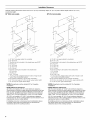
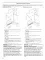
Installation Clearances
Cabinet opening dimensions shown are for 25" (64 cm) countertop depth, 24" (61 cm) base cabinet depth and 36" (91.4 cm)
countertop height.
30" (76.2 cm) models 36" (91.4 cm) models
A
C _
A. 18" (45.7 cm) upper cabinet to countertop
B.22" (55.9 cm)
C. Junction box to be located in this shaded area, see NOTE*
D. 4" (10.2 cm)
E.20" (50.8 cm)
F. 12" (30.5 cm)
G. 5_//' (14 cm)
H. Gas line opening to be located in this shaded area
/.3Y2" (8.9 cm)
J. 8" (20.3 cm)
K.30_/4" (76.8 cm)
L. 4" (10.2 cm) min. clearance from both sides of range to side
wall or other combustible material
M. For minimum clearance to top of range, see NOTE**
N. 30" (76.2 cm) model: 30" (76.2 cm) min. upper cabinet width
O. 13" (33 cm) max. upper cabinet depth
*NOTE: Receptacle must be rotated 90° for Canadian
installation.
**NOTE: Minimum Clearances
30" (76.2 cm) models: 36" (91.4 cm) minimum clearance
When bottom of wood or metal cabinet is protected by not less
than W' (0.64 cm) flame retardant millboard covered with not
less than No. 28 MSG sheet steel, 0.015" (0.4 mm) stainless
steel, 0.024" (0.6 ram) aluminum or 0.020" (0.5 mm) copper.
30" (76.2 cm) models: 42" (106.7 cm) minimum clearance
between the top of the cooking platform and the bottom of an
unprotected wood or metal cabinet.
If installing a hood or a microwave hood combination above
the range, follow the hood instructions for dimensional
clearances above the cooktop surface.
A. 18"(45.7 cm)upper cabinet to countertop
B.28" (71.1 cm)
C. Junction box to be located in thisshaded area, see NOTE*
D.4" (10.2cm)
E.20" (50.8 cm)
F. 12" (30.5 cm)
G.5F2"(14cm)
H. Gasline opening to be located in this shadedarea
L 8_2" (8.9 cm)
J. 8" (20.3 cm)
K.86_/4"(92.1 cm)
L.4" (10.2cm) min. clearance from both sides of range toside
wall or other combustible material
M. For minimum clearance to top of range,see NOTE**
N. 36" (91.4cm) model: 36" (91.4cm) min. upper cabinet width
O.13" (33cm)max. upper cabinet depth
*NOTE: Receptacle must be rotated 90° for Canadian
installation.
**NOTE: Minimum Clearances
36" (91.4 cm) models: 42" (106.7 cm) minimum clearance
When bottom of wood or metal cabinet is protected by not less
than _/4"(0.64 cm) flame retardant millboard covered with not
less than No. 28 MSG sheet steel, 0.015" (0.4 mm) stainless
steel, 0.024" (0.6 mm) aluminum or 0.020" (0.5 mm) copper.
36" (91.4 cm) models: 48" (121.9 cm) minimum clearance
between the top of the cooking platform and the bottom of an
unprotected wood or metal cabinet.
If installing a hood or a microwave hood combination above
the range, follow the hood instructions for dimensional
clearances above the cooktop surface.

ElectricalShockHazard
Electricallygroundrange.
Failure to do so can result in death, fire, or
electrical shock.
codes permit and a separate ground wire is used, it is
recommended that a qualified electrical installer determine that
the ground path and wire gauge are in accordance with local
codes.
Be sure that the electrical connection and wire size are adequate
and in conformance with the CSA Standard C22.1, Canadian
Electrical Code, Part 1 - latest edition, and all local codes and
ordinances.
A copy of the above code standards can be obtained from:
Canadian Standards Association
178 Rexdale Blvd.
Toronto, ON M9W 1R3 CANADA.
• Do not ground to a gas pipe.
• Check with a qualified electrical installer if you are not sure
the range is properly grounded.
• Do not have a fuse in the neutral or ground circuit.
• When a 4-wire, single phase 208/240 volt, 60 Hz., AC only
electrical supply is available, a 30-amp minimum circuit
protection is required, fused on both sides of the line.
• A time-delay fuse or circuit breaker is recommended.
• This range is equipped with a CSA International Certified
Power Cord intended to be plugged into a standard 14-50R
wall receptacle. Be sure the wall receptacle is within reach of
range's final location.
• Do not use an extension cord.
I_ _, I:_ ...... .......... ,_ , ....
Explosion Hazard
Use a new CSA international approved gas supply line.
Install a shut-off valve.
Securely tighten all gas connections.
If connected to LP, have a qualified person make sure
gas pressure does not exceed 14" (36 cm) water
column.
Examples of a qualified person include:
licensed heating personnel,
authorized gas company personnel, and
authorized service personnel.
Failure to do so can result in death, explosion, or fire.
Observe all governing codes and ordinances.
IMPORTANT: This installation must conform with all local codes
and ordinances. In the absence of local codes, installation must
conform with American National Standard, National Fuel Gas
Code ANSI Z223.1 - latest edition or CAN/CGA B149 - latest
edition.
IMPORTANT: Range cooktop must be connected to a regulated
gas supply.
Type of Gas
Natural Gas:
This range is design-certified by CSA International for use with
Natural gas or, after proper conversion, for use with LP gas.
• This range is factory set for use with Natural gas. The model/
serial rating plate located on the right vertical surface of the
oven door frame has information on the types of gas that can
be used. Ifthe types of gas listed do not include the type of
gas available, check with the local gas supplier.
LP Gas conversion:
Conversion must be done by a qualified service technician.
No attempt shall be made to convert the appliance from the gas
specified on the model/serial rating plate for use with a different
gas without consulting the serving gas supplier. To convert to LP
gas, use the LP gas conversion kit provided with your range. The
parts for this kit are in the literature package supplied with the
range.

Gas Supply Line
Provide a gas supply line of 3A"(1.9 cm) rigid pipe to the
range location. A smaller size pipe on longer runs may result
in insufficient gas supply. Pipe-joint compounds that resist
the action of LP gas must be used. Do not use TEFLON °t
tape. With LP gas, piping or tubing size can be 1/2"(1.3 cm)
minimum. Usually, LP gas suppliers determine the size and
materials used in the system.
Flexible metal appliance connector:
If local codes permit, a new CSA design-certified,
4 - 5 ft (122 - 152.4 cm) long, %" (1.6 cm) or
3A"(1.9 cm) I.D., flexible metal appliance connector may
be used for connecting range to the gas supply line.
• A r/2" (1.3 cm) male pipe thread is needed for connection
to the female pipe threads of the inlet to the appliance
pressure regulator.
• Do not kink or damage the flexible metal tubing when
moving the range.
Rigid pipe connection:
The rigid pipe connection requires a combination of pipe
fittings to obtain an in-line connection to the range. The rigid
pipe must be level with the range connection. All strains must
be removed from the supply and fuel lines so range will be
level and in line.
Must include a manual shutoff valve:
The supply line must be equipped with a manual shutoff
valve. This valve should be located in the same room but
external to the range. It should be in a location that allows
ease of opening and closing. Do not block access to shutoff
valve. The valve is for turning on or shutting off gas to the
range.
B
\
A
A. Gas supply line
B. Shutoff valve "open" position
C. To range
Gas Pressure Regulator
The gas pressure regulator supplied with this range must be
used. The inlet pressure to the regulator should be as follows for
proper operation:
Natural Gas:
Minimum pressure: 6" (15.2 cm) WCP
Maximum pressure: 14" (35.6 cm) WCP
LP Gas:
Minimum pressure: 11" (27.9 cm) WCP
Maximum pressure: 14" (35.6 cm) WCP
Contact local gas supplier if you are not sure about the inlet
pressure.
Burner Input Rating - Altitude
Input ratings shown on the model/serial rating plate are for
elevations up to 2,000 ft (609.6 m).
For elevations above 2,000 ft (609.6 m), ratings are reduced at a
rate of 4% for each 1,000 ft (304.8 m).
Gas Supply Pressure Testing
Line pressure testing above 1/2psi gauge (14" WCP)
The range and its individual manual shutoff valve must be
disconnected from the gas supply piping system during any
pressure testing of that system at test pressures greater than
r/2psi (3.5 kPa).
Line pressure testing at 1/2psi gauge (14" WCP) or lower
The range must be isolated from the gas supply piping system by
closing its individual manual shutoff valve during any pressure
testing of that system at test pressures equal to or less than
r/2psi (3.5 kPa).
t®TEFLON is a registered trademark of E.I. Du Pont De Nemours and Company.

INSTALLATION INSTRUCTIONS
Excessive Weight Hazard
Use two or more people to move and install range.
Failure to do so can result in back or other injury.
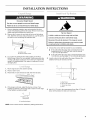
1. Remove shipping materials, tape and protective film from
range. Keep shipping pallet under range. Remove oven racks,
grates and parts package from inside oven.
2. Remove the 2 screws on each side of the top of the bottom
vent. Slide the vent down and pull toward you. Lay this part to
the side to avoid scratching the stainless steel.
3.
A
A. Bottom vent
B. Remove these screws.
Lay a piece of cardboard from side packing on the floor
behind range. Using 2 or more people, firmly grasp each side
of range. Lift range up about 3" (8 cm) and move it back until
range is off shipping pallet. Set range on cardboard to avoid
damaging floor.
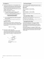
f. Move range close to the cabinet opening.
2. Place a rack in oven.
3. Place level on rack, first side to side, then front to back.
4.
If the range is not level, adjust the feet up or down. Turn
leveling leg sleeves to level range and to raise or lower range
to the desired countertop height.
Tip Over Hazard
A child or adult can tip the range and be killed.
Connect anti=tip bracket to wail behind range,
Reconnect the anti-tip bracket, if the range is moved.
Failure to follow these instructions can result in death
or serious burns to children and adults.
1. Choose the correct anti-tip bracket for your installation.
• Ifthe wall behind the range has no baseboard or has a
baseboard up to 3/8"(0.95 cm) thick, use the shorter
1" (2.5 cm) anti-tip bracket.
• Ifthe wall behind the range has a baseboard thicker than
3/8"(0.95 cm), use the longer 13A"(4.4 cm) anti-tip bracket.
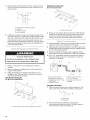
2. Locate a stud on the wall behind the range. Measure the
distance from top of rear brace to floor.
3.
C
B
A. Rear brace
B. Top of rear brace to floor
C. Top of rear brace
D. Floor
Add 5/16"(0.79 cm) to the measurement from Step 2. This will
allow anti-tip bracket to slide over rear brace.
A. Leveling legsleeve
NOTE: Oven must be level for satisfactory baking performance.

4. Attaching the Island Trim
36" (91.4} model shown
5=
Using the final measurement from Step 3, measure from the
floor up and mark a horizontal line on the wall where a wall
stud is located.
i
j
I
D I
I
' , I
I I
I I
I
A. Horizontal line marked from Step 4.
B. Wall stud
C. Mounting screws
D. Anti-tip bracket
Position top of anti-tip bracket at line marked in Step 4 and
mark holes. Drill two 1/8"holes at the positions marked on the
wall. Use screws provided to fasten anti-tip bracket to wall.
Anti-tip bracket must be mounted securely to stud in wall
behind the range. Depending on thickness of the wall, longer
screws may be required. Longer screws are available from
your local hardware store.
Excessive Weight Hazard
Use two or more people to move and install range.
Failure to do so can result in back or other injury.
1. Using 2 or more people, move range close to cabinet
opening.
2. Remove cardboard or hardboard from under range. Move
range into final position.
3. Attach the backguard or island trim as required for your
installation. See "Tools and Parts." Attachment screws are
included in the literature package.
Attaching the Backguard
36" (91.4 cm) model shown
A. 3 front screws (4 rear screws required but not shown)
A. Center hole not used
4=
Using 2 or more people, tip the range back so that the front
feet lift off the ground. Slide range toward the wall until the
rear brace is under the anti-tip bracket. Stand range up,
making sure the anti-tip bracket catches the rear brace.
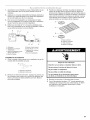
1. Assemble flexible connector from gas supply pipe to pressure
regulator located in the middle front of the range.
2, Apply pipe-joint compound made for use with LP gas to the
smaller thread ends of the flexible connector adapters (see B
and G in following illustration).
3. Attach one adapter to the gas pressure regulator and the
other adapter to the gas shutoff valve. Tighten both adapters.
4. Use a Wld' combination wrench and channel lock pliers to
attach the flexible connector to the adapters. Check that
connector is not kinked.
A
B C
D
_ E
H G
A. Gas pressure regulator
B. Use pipe-joint compound
C. Adapter (must have Y2"male
pipe thread)
D. Flexible connector
F
E Manual gas shutoff valve
F Y," or 3/4"gas pipe
G. Use pipe-joint compound
H. Adapter
Complete Connection
1. Open the manual shutoff valve in the gas supply line. The
valve is open when the handle is parallel to the gas pipe.
2=
A.Closed valve
B.Open valve
Test all connections by brushing on an approved
noncorrosive leak-detection solution. If bubbles appear, a
leak is indicated. Correct any leak found.
10

3=
Remove cooktop burner caps, grates and simmer plate from
parts package. Align notches in burner caps with pins in
burner base. Burner caps should be level when properly
positioned. If burner caps are not properly positioned,
surface burners will not light. Place burner grates over
burners and caps.
A. Burner base
B. Burner cap
C. Burner grate
D. Simmer plate
4.
5.
Electrical Shock Hazard
Plug into a grounded 3 prong outlet.
Do not remove ground prong.
Do not use an adapter.
Do not use an extension cord.
Failure to follow these instructions can result in death,
fire, or electrical shock.
Plug into a grounded 3 prong outlet.
Turn on power supply. "PF" should appear on the clock
display. For further information, please refer to the user
instructions located in the Use and Care Guide.
Initial lighting and gas flame adjustments
Cooktop and oven burners use electronic igniters in place of
standing pilots. When the cooktop control knob is turned to the
"LITE" position, the system creates a spark to light the burner.
This sparking continues, as long as the control knob is turned to
"LITE."
Check Operation of Cooktop Burners
Push in and turn each control knob to the "LITE" position.
The flame should light within 4 seconds. The first time a burner is
lit it may take longer than 4 seconds to light because of air in the
gas line.
If burners do not light properly:
• Turncooktop control knob to the "OFF" position.
• Check that the range is plugged in and the circuit breaker has
not tripped or the household fuse has not blown.
• Check that the gas shutoff valves are set to the "open"
position.
• Check that burner caps are properly positioned on burner
bases.
Repeat start-up. If a burner does not light at this point, contact
your dealer or authorized service company for assistance.
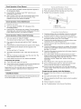
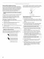
Adjust Flame Height
Adjust the height of top burner flames. The cooktop "low" burner
flame should be a steady blue flame approximately 1A"(0.64 cm)
high.
/
A. Low flame
B. High flame
The flame can be adjusted using the adjustment screw in the
center of the valve stem. The valve stem is located directly
underneath the control knob.
A
A. Adjustment screw
If the "low" flame needs to be adjusted:
1. Remove the control knob.
2. Hold the knob stem with a pair of pliers. Use a small flat-
blade screwdriver to turn the screw located in the center of
the control knob stem until the flame is the proper size.
3. Replace the control knob.
4. Test the flame by turning the control from "LO" to "HI,"
checking the flame at each setting.
11

Check Operation of Oven Element
1. Turn oven selector to BAKE. Default temperature appears in
the temperature display.
2. Press ENTER. The display reads "PrE" when the oven
temperature begins to rise.
3. Wait 2 minutes, open oven door and hold hand above oven
floor and feel for heat. Do not touch oven floor. Press
CANCEL and turn oven selector to RESET.
Check Operation of Oven Broil Element
1. Close the oven door.
2. Turn oven selector to BROIL. "HI" will appear in the
temperature display.
3. Press ENTER. Look through oven window. The top element
should glow red, and heat should be radiating out of the door.
Press CANCEL and turn oven selector to RESET.
Check Operation of Steam Assist Technology
1. Turn oven selector to "SELECT STEAM."
The indicator light will flash next to "HIGH STEAM."
2. Pour water into the water inlet until the "HALF" indicator
lights up.
3. Press ENTER and default temperature appears in the display.
4. Press ENTER and the default cook time appears in the
display.
Set the cook time to 10 minutes.
5. The display will indicate "LoAd." Open and close the oven
door.
6. After the 10 minutes counts down, open the oven door. The
cavity should be warm and moist.
7. Press CANCEL and turn the oven selector and RESET.
If oven does not operate:
• Check that power supply is turned on.
• Check that the range is plugged in and the circuit breaker has
not tripped or the household fuse has not blown.
Repeat start-up. If the oven still does not operate at this point,
contact your dealer or authorized service company for
assistance.
Install Burner Grates
Place burner grates over burner caps. The simmer plate may sit
on one of the grates or be stored for future use.
1. Insert lower vent tabs into the slots on the front trim.
2. Push vent upward until the holes line up at top of vent.
3. Reattach the vent using the 4 screws.
A
A.Bottom vent
B.Reattach thesescrews.
1. Check that all parts are now installed. If there is an extra part,
go back through the steps to see which step was skipped.
2. Check that range is correctly positioned in countertop cutout
and that the range is level. See "Level Range."
3. Check that the specified distances to cabinet surfaces were
maintained. See "Location Requirements."
4. Check that burner caps are positioned properly on sealed
burner bases.
5. Check that backguard or island trim is installed. (If horizontal
clearance to combustible materials behind cooking surface is
less than 1" [2.5 cm]).
6. Check that the range is connected only to the type of gas for
which it is certified for use.
7. Use a mild solution of liquid household cleaner and warm
water to remove waxy residue caused by protective shipping
material. Dry thoroughly with a soft cloth. For more
information, see the "Range Care" section of the Use and
Care Guide.
8. Read "Range Use" in the range Use and Care Guide.
9. Turn on surface burners and oven. See your Use and Care
Guide for specific instruction on range operation.
10. Once the oven has cooled down, you may drain the water
reservoir. Read "Water Reservoir Drain Operation" in the Use
and Care Guide.
If range does not operate, check the following:
• Household fuse has not blown or circuit breaker has not
tripped.
• Gas valves are turned to the "ON" position.
• If the gas supply line shutoff valve is open contact a qualified
technician.
• Electrical supply is connected.
• See "Troubleshooting" in the Use and Care Guide.
12

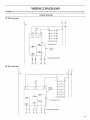
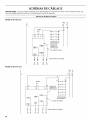
WIRING DIAGRAMS
CAUTION: Label all wires prior to disconnection when servicing controls. Wiring errors can cause improper and dangerous operation.
Cooktop Schematic
30" (76.2 cm) model
36" (91.4 cm) model
L1
L1 N L2
W( o
BK R
GND W
q_ q_ q _
1
I
VALVESWITCHES
SPARKMODULE
_ Y0rBR
(4)PLCS
I
t IGNITERELECTRODES
BK
W
g=-
R
=F
g
g
g
[_
GND
W
g g
_ SPARK
_ MODULE
W
_o---
_o--_
---r'fO---_
...._o.-.-_o......._
__o.-._o__,,
VALVESWITCHES
Y ORBR (6) PLCS
IGNITERELECTRODES
N L2
)
W R
13

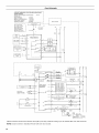
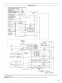
Oven Schematic
IICLASSIC COMMERCIAL STYLE OVEN WITH STEAM ASSIST
I WIRING DIAGRAM
IiModelS KDRP767RSSOO & KDRP707RSOO VER 12
117th May '05
IIMAIN HARNESS #9758951
ISIGNAL HARNESS (display) #9761098
IIOVEN LIGHT JUMPER #9761106
_HARNESS SENSOR #9758957
L .................................... J
aiJP21 =AMP 640454-8
iJP11 =AMP 1-1123723-3
IJR24 =AMP 640454-7
IJP03 =AMP 1-1123723-4
IiJP02 _JST B2B-XH 2P
iJR 16,JP4,JP5,JPT,JP8,
IJP9,JP10= Tap 6,3"0,8mm
I'
i NTC I 2 _ v
L ....... I
I
II tank +water
I level sensor L ---E.-MP2"--_[_
I I
I I VEE,GND _K
L. ....... I
Wide connector Rx/Tx
to Taurus board -- ¥--'4
JP9 - oa -<
GND
w....... _ 2
II Drain Pump __=_____(
I switch I
I
Pin 1 NC _r
,}. 7
I a¥
O
J¢_
STEAM BOARD
_1'21-1
_-_-,._£°L_
JPI4 r--_- - -
I
,p_l_ I ,P04
,I,-_o__-v
I
JpI.3 -- P _
__ p,
t I
1
1
display board
........ ,?=_.... _ t6
_, 8 enter button
connector
'1
I
I
i
gemini 2 board _-
I
N L1
w _
"A_
,.. j ... ,..
_,BK
R
L2
C_
w....... _
i
Cance_ KEY _
JP40 _2
Lt
"_ 12 JRO4
%
%
I Wide connector to steam I
board JP11 I 1 o_
w Y
TEMP SENSOR
10800 A_ 21 _C (70_F)
1654_ AT 177°0 (350"F)
L_CH SW:_CH
G¥
_L_C-RON:CCO_TRO_
bOUB_ _=NE
P4 - 2 £REAKREb_¥
JPI9
P9-2 APPLIANCE pa-3
MANAGER Pa-
P9-1
P1-7
P7 - 4
P3 - ,3
P3 - 2
P7 - 8
P1-5
,-o-----
O
p7-7 P1-3
0
P7 - 6
"0-
ELECTRON!C FILTER -
WP 4451985
N L2 L1
(
...... R
*Blower remains off until oven reaches 190°F (88°C) and may continue running up to 45 minutes after oven has turned off.
NOTE: Circuit is shown in standby/off mode with oven door closed.
14

P P
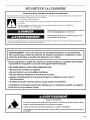
SECURITE DE LA CUISINIERE
Votre s6curit6 et celle des autres est tr6s importante.
Nous donnons de nombreux messages de s6curite importants dans ce manuel et sur votre appareil menager. Assurez-vous de
toujours lire tous les messages de securite et de vous y conformer.
Voici le symbole d'alerte de securit&
Ce symbole d'alerte de securite vous signale les dangers potentiels de deces et de blessures graves & vous
et &d'autres.
Tousles messages de securite suivront le symbole d'alerte de securite et le mot "DANGER" ou
"AVERTISSEMENT". Ces mots signifient :
Risque possible de deces ou de blessure grave si vous ne
euivez pas immediatement lee instructions.
Risque possible de deces ou de blessure grave si vous
ne euivez pas lee instructions.
Tousles messages de securite vous diront quel est le danger potentiel et vous disent comment reduire le risque de blessure et
ce qui peut se produire en cas de non-respect des instructions.
AVERTISSEMENT : Pour votre s6curit6, les renseignements dans ce manuel doivent
_tre observ6s pour r6duire au minimum les risques d'incendie ou d'explosion ou pour
6viter des dommages au produit, des blessures ou un d6c_s.
- Ne pas entreposer ni utiliser de I'essence ou d'autres vapeurs ou liquides inflammables
proximit6 de cet appareil ou de tout autre appareil 61ectrom6nager.
- QUE FAIRE DANS LE CAS D'UNE ODEUR DE GAZ :
• Ne pas tenter d'allumer un appareil.
• Ne pas toucher a un commutateur 61ectrique.
• Ne pas utiliser le t616phone se trouvant sur les lieux.
• Appeler imm6diatement le fournisseur de gaz d'un t616phone voisin. Suivre
ses instructions.
• A d6faut de joindre votre fournisseur de gaz, appeler les pompiers.
- L'installation et I'entretien doivent _tre effectu6s par un installateur qualifi6, une agence
de service ou le fournisseur de gaz.
Risque de baeculement
Un enfant ou une personne adulte peut faire baeculer la cuisini_re ce qui peut causer un decks.
Joindre la bride antibaeculement au mur derriere la cuisini_re.
Joindre de nouveau la bride antibaeculement si la cuisini_re eet deplacee.
Le non-respect de cee instructions peut causer un deces ou dee brt31ures graves aux enfants et
aux adultes.
15

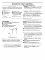
EXIGENCES DqNSTALLATION
Rassembler les outils et pieces necessaires avant de commencer
I'installation. Lire et suivre les instructions fournies avec les outils
indiques ici.
Outillage n_cessaire
• Metre-ruban • Marqueur ou crayon
• Tournevis a lame plate • Ruban adhesif de masquage
• Tournevis Phillips • Compose d'etancheite des
raccords filetes - resistant
• Niveau
au propane
• Perceuse manuelle ou
electrique • Solution non-corrosive de
detection des fuites
• Pince multiprise ordinaire
• Detecteur magnetique de vis
• Cle a tube
• Cle mixte de 1_A6"
Pi_ces n_cessaires
• Un connecteur de conduit (homologation UL ou CSA)
• Un serre-fils homologue UL
Pi_ces fournies
Verifier que toutes les pieces sont presentes.
• Trousse de bride antibasculement
_cf" i (4,4orn)
LLJ
B
A. Bride antibasculement
B. Vis a t_te Phillips n° !0 x 2" (2)
REMARQUE : Les brides doivent _tre solidement fixees au
poteau mural. La profondeur du mur peut necessiter des vis plus
Iongues pour I'ancrage de la bride dans lemur. Des vis plus
Iongues sont disponibles aupres de votre quincaillerie locale. Voir
la section "Bride antibasculement".
• Dosseret et vis de fixation (7).
REMARQUE : La garniture en riot incluse avec la cuisiniere
peut _tre utilisee en cas d'installation a 1" (2,5 cm) (modele
de 30" [76,2 cm]) ou 5" (12,7 cm) (modele de 36" [91,4 cm])
d'une cloison arriere combustible ou en cas d'installation a 0"
(0 cm) d'une cloison arriere non-combustible.
• Garniture en riot et vis de fixation (3).
REMARQUE : La garniture en riot incluse avec la cuisiniere
peut _tre utilisee en cas d'installation a 1" (2,5 cm) d'une
cloison arriere combustible ou a 0" (0 cm) d'une cloison
arriere non-combustible.
• Trousse de conversion pour I'alimentation au propane
REMARQUE : La table de cuisson est con(_ue pour une
utilisation au gaz naturel. Pour effectuer la conversion pour
une alimentation au propane, voir les instructions de
conversion de gaz fournies dans le sachet de documentation.
Verifier les codes Iocaux et consulter le fournisseur de gaz.
Verifier I'alimentation en gaz et I'alimentation electrique
existantes. Voir les sections "Specifications electriques" et
"Specifications de I'alimentation en gaz".
Toutes les connexions electriques doivent _tre effectuees par un
electricien qualifie et certifie.
IMPORTANT : Observer les dispositions de tous les codes et
r_glements en vigueur. Ne pas obstruer le flux de combustion et
la ventilation.
• C'est a I'installateur qu'incombe la responsabilite de
respecter les distances de separation exigees, specifiees sur
la plaque signaletique de I'appareil. La plaque signaletique
des numeros de modele et de serie est situee sur la surface
verticale sous le panneau de commande a droite.
• II est recommande d'installer une hotte de cuisiniere de
600 CFM ou plus au-dessus de la cuisiniere.
• Dans le cas d'une cuisiniere encastree, I'enceinte doit
recouvrir completement les c6tes et I'arriere de la cuisiniere.
Afin de supprimer le risque de brelures ou d'incendie en se
penchant au-dessus des unites de surface chauffees, le
rangement en armoire au-dessus des unites de surface doit
6tre evite. Si le rangement en armoire est envisage, le risque
peut _tre reduit par I'installation d'une hotte de cuisine
operant horizontalement sur un minimum de 5" (12,7 cm) au-
dela du bas des placards.
• Toutes les ouvertures dans lemur ou le plancher de
I'emplacement d'installation de la cuisiniere doivent _tre
scellees.
• Ne pas realiser un scellement entre la cuisiniere et les
placards lateraux.
• Respecter les dimensions indiquees pour la cavite
d'installation entre les placards. Ces dimensions constituent
les valeurs minimales des degagements de separation.
La bride antibasculement murale doit _tre installee. Pour
I'installation de la bride antibasculement expediee avec la
cuisiniere, voir la section "Installation de la bride
antibasculement .
16

• Une source d'electricite avec liaison & la terre est necessaire.
Voir la section "Specifications electriques'.
• Une source de gaz adequate doit _tre disponible. Voir la
section "Specifications de I'alimentation en gaz".
Contacter un installateur de rev_tement de sol qualifie, qui
pourra determiner si le rev_tement de sol peut resister a une
temperature d'au moins 200°F (93°C). Dans le cas de
I'installation de la cuisiniere sur un tapis, placer sous la
cuisiniere une plaque d'appui isolee, ou une plaque de
contreplaque de 1A"(0,64 cm).
IMPORTANT : Les materiaux de certains placards et certains
materiaux de construction ne sont pas congus pour resister a la
chaleur generee par le four durant la cuisson au four ou
I'autonettoyage. Consulter le constructeur de la maison ou le
fabricant des placards pour determiner si les materiaux utilises
pourraient subir un changement de couleur, une destratification
ou d'autres dommages.
R_sidence mobile - Specifications additionnelles
respecter Iors de I'installation
L'installation de cette cuisiniere doit _tre conforme aux
dispositions de la norme Manufactured Home Construction and
Safety Standard, Title 24 CFR, Part 3280 (anciennement Federal
Standard for Mobile Home Construction and Safety, Title 24,
HUD Part 280). Lorsque cette norme n'est pas applicable,
I'installation doit satisfaire aux criteres de la norme Standard for
Manufactured Home Installations, ANSI A225.1/NFPA 501A ou
aux dispositions des codes Iocaux.
Au Canada, I'installation de cette cuisiniere doit satisfaire aux
stipulations de la version la plus recente de la norme CAN/CSA-
A240 ou des codes Iocaux en vigueur.
Autres crit_res _ respecter pour une installation en residence
mobile :
• Dans le cas de I'installation de cette cuisiniere dans une
residence mobile, la cuisiniere doit _tre fixee au plancher
durant tout deplacement du vehicule. Toute methode de
fixation de la cuisiniere est adequate darts la mesure o(J elle
satisfait aux criteres des normes mentionnees ci-dessus.
Dimensions du produit
ModUles de 30" (76,2 cm) ModUles de 36" (91,7 cm)
f
B
B
\
A. Dosseret (exig_ pour certaines installations)
B. Hauteur hors-tout 45" (114,3 cm)
C. Hauteur de la table de cuisson 36" (91,4 cm) avec pieds
d_viss_s de 3/4tour
D. 30" (76,2 cm) de largeur
E. 26Y2" (67,3 cm) de largeur (tableau de commande
indus), voir REMARQUE*
Butte d'espacement de _ " (6,4 cm)
G. Hauteur du dosseret 9Y_" (23,5 cm)
A. Dosseret (exig_ pour certaines installations)
B. Hauteur hors-tout 45" (114,3 cm)
C. Hauteur de la table de cuisson 36" (91,4 cm) avec pieds
d_viss_s de _/_tour
D. 36" (91,4 crn) de largeur
E. 26F2" (67,3 cm) de largeur (tableau de commande
indus), voir REMARQUE*
F. Butte d'espacement de _ " (6,4 crn)
G. Hauteur du dosseret 9_ " (23,5 cm)
*REMARQUE : Dans le cas d'une installation entre des placards de 24" (61 cm) avec plan de travail de 25" (63,5 cm), I'avant de la
porte du four sera en saillie de 1%" (4,8 cm) au-dela de la fagade des placards de 24" (61 cm).
17

D_gagements de s_paration a respecter
Les dimensions de I'espace d'installation entre les placards sont valides pour I'installation entre des placards de 24" (61 cm) avec plan
de travail de 25" (64 cm) de profondeur et hauteur de 36" (91,4 cm).
ModUles de 30" (76,2 crn) ModUles de 36" (91,4 crn)
A
C*
A. 18" (45, 7 cm) entre le placard sup_rieur et le plan de travail
B.22" (55,9 cm)
C. Placer la bofte de connexion dans cette zone ombr_e, voir
REMARQUE*
D. 4" (10,2 cm)
E.20" (50,8 cm)
F: 12" (30,5 cm)
G. 5Y2" (14 cm)
H. Placer la canailsation de gaz dans cette zone ombr_e
/.3Y/' (8,9 cm)
J. 8" (20,3 cm)
K.30Y_" (76,8 cm)
L. D_gagement de 4" (10,2 cm) minfinum entre les deux c6t_s
de la cuisini@re et les patois lat_rales ou d'autres mat_riaux
combustibles
M. Pour la distance fibre minimale vers la pattie sup_rieure de la
cuisiniere, voir la REMARQUE**
N. Modole de 30" (76,2 cm) : Largeur min. du placard sup_rieur
30" (76,2 cm)
O. Profondeur max. du placard sup_rieur !3" (33 cm)
*REMARQUE : Pour installation au Canada, il est n@cessaire de
faire pivoter la prise de 90°.
**REMARQUE : D_gagements minimums
Mod@les de 30" (76,2 cm) : d@gagement min. de 36" (91,4 cm)
Lorsque le fond d'un placard de bois ou de m@talest prot@g@
par une planche ignifug@e d'au moins 1/4"(0,64 cm) recouverte
d'une feuille m@tallique d'@paisseur @galeou sup@rieure a :
acier calibre 28 MSG, acier inoxydable 0,015" (0,4 mm),
aluminium 0,024" (0,6 mm), ou cuivre 0,020" (0,5 mm).
Mod@les de 30" (76,2 cm) : Distance de s@paration de
42" (107 cm) ou plus entre le dessus de latable de cuisson et
le fond d'un placard de bois ou de m@talnon prot@g&
En cas d'installation d'une hotte ou d'un ensemble hotte/
micro-ondes au-dessus de la cuisini@re, suivre les instructions
fournies avec la hotte concernant les dimensions de
CUlSSOn.
A. 18" (45, 7 cm) entre le placard sup_rieur et le plan de travail
B. 28" (71,1 cm)
C. Placer la boTte de connexion dans cette zone ombr_e, voir
REMARQUE*
D. 4" (10,2 cm)
E: 20" (50,8 cm)
t_ 12" (30,5 cm)
G. 5F2" (14 cm)
H. Placer la canafisation de gaz dans cette zone ombr_e
L 3F2" (8,9 cm)
J. 8" (20,3 cm)
K. K. 36Y4" (92,1 cm)
L. D_gagement de 4" (10,2 cm) minimum entre les deux c6t#s
de la cuisiniore et les patois lat_rales ou d'autres mat_riaux
combustibles
M. Pour la distance libre minimale vers la partie sup_rieure de la
cuisini@re, veir la REMARQUE**
N. Modole de 36" (91,4 cm) : Largeur min. du placard sup_rieur
36" (9!,4 cm)
O. Profondeur max. du placard sup_rieur 13" (33 cm)
*REMARQUE : Pour installation au Canada, il est n@cessaire de
faire pivoter la prise de 90°.
**REMARQUE : D_gagements minimums
Mod@les de 36" (91,4 cm) : d@gagement rain. de 42" (106,7 cm)
Lorsque le fond d'un placard de bois ou de m@talest prot@g@
par une planche ignifug@e d'au moins W' (0,64 cm) recouverte
d'une feuille m@tallique d'@paisseur @galeou sup@rieure a :
acier calibre 28 MSG, acier inoxydable 0,015" (0,4 mm),
aluminium 0,024" (0,6 ram), ou cuivre 0,020" (0,5 mm).
Mod@les de 36" (91,4 cm) : Distance de s@paration de 48"
(121,9 cm) ou plus entre le dessus de la table de cuisson et le
fond d'un placard de bois ou de m@talnon prot@g&
En cas d'installation d'une hotte ou d'un ensemble hotte/
micro-ondes au-dessus de la cuisini@re, suivre les instructions
fournies avec la hotte concemant les dimensions de
d@gagement a respecter au-dessus de la surface de la table de
CUlSSOn.
18

Risque de choc electrique
Relier la cuisiniere a la terre.
Le non-respect de cette instruction peut causer
un deces, un incendie ou un choc electrique.
Si le code en vigueur le permet et qu'un conducteur distinct de
liaison a la terre est utilise, on recommande qu'un electricien
qualifie verifie que la liaison a la terre et la taille du conducteur de
liaison a la terre sont conformes aux prescriptions du code local.
Verifier que le raccordement a la source d'electricit6 et le calibre
des conducteurs sont adequats et conformes aux prescriptions
de la plus recente edition de la norme CSA C22.1, partie 1 - Code
canadien de I'electricit6, et de tout code ou reglement local en
vigueur.
On peut obtenir un exemplaire de la norme ci-dessus aupres de :
Canadian Standards Association
178 Rexdale Blvd.
Toronto, ON M9W 1R3 CANADA.
• Ne pas utiliser une tuyauterie de gaz pour le raccordement
la terre.
• En cas de doute quanta la qualite de la liaison a la terre de la
cuisiniere, consulter un electricien qualifie.
• Ne pas installer un fusible dans le conducteur neutre ou le
conducteur de liaison a la terre.
Lorsqu'une source d'_lectricite monophase de 208/240 volts,
60 Hz/4 conducteurs (CA uniquement) est disponible, le
circuit dolt comporter un dispositif de protection 30 amperes,
fusionne aux deux extremit6s de la ligne.
• On recommande I'emploi de fusibles temporises ou
disjoncteurs.
Cette cuisiniere est dotee d'un dispositif de branchement
(homologation CSA International) destine a _tre branche sur
une prise de courant murale standard 14-50R. Veiller ace
que la prise de courant murale soit placee a portee de la
position de service finale de la cuisiniere.
• Ne pas utiliser de c&ble de rallonge.
Risque d'explosion
Utiliser une canalisation neuve d'arrivee de gaz
approuvee par la CSA international,
installer un robinet d'arr_t.
Bien serrer chaque organe de connexion de la
canalisation de gaz.
En cas de connexion au gaz propane, demander a une
personne qualifiee de s'assurer que la pression de gaz
ne depasse pas 36 cm (14 po) de la colonne d'eau.
Par personne qualifiee, on comprend :
le personnel autorise de chauffage,
le personnel autorise d'une compagnie de gaz, et
le personnel d'entretien autorise.
Le non-respect de ces instructions peut causer
un deces, une explosion ou un incendie.
Observer toutes les prescriptions des codes et reglements en
vigueur.
IMPORTANT : L'installation dolt satisfaire aux criteres de tousles
codes et reglements Iocaux. En I'absence de code local,
I'installation dolt satisfaire aux prescriptions de la plus recente
edition du code national en vigueur : National Fuel Gas Code
ANSI Z223.1 (American National Standard), ou CAN/CGA B149.
IMPORTANT : La table de cuisson de la cuisiniere dolt _tre
raccordee a une source d'alimentation en gaz regulee.
Type de gaz
Gaz naturel :
La conception de cette cuisiniere a ete homologuee par CSA
International pour I'alimentation au gaz naturel, ou pour
I'alimentation au propane apres conversion adequate.
• Cette cuisiniere a ete configuree a I'usine pour I'alimentation
au gaz naturel. La plaque signaletique des numeros de
modele et de serie situee sur la surface verticale a droite du
cadre de la porte du four presente des informations sur les
types de gaz a utiliser. Si le type de gaz disponible n'est pas
mentionne sur la plaque signaletique, consulter le fournisseur
de gaz local.
Conversion pour I'alimentation au propane :
L'op_ration de conversion dolt _tre ex_cut_e par un
technicien qualifi_.
Consulter le fournisseur de gaz avant toute conversion de
I'appareil pour I'utilisation d'un type de gaz qui n'est pas
mentionne sur la plaque signaletique. Pour convertir au gaz
propane, utiliser le kit de conversion fourni avec la cuisiniere. Les
pieces pour ce kit se trouvent dans le sachet de documentation
fourni avec la cuisiniere.
19

Canalisation de gaz
Installer une canalisation de gaz rigide de 3A"(1,9 cm) jusqu'&
I'emplacement d'installation de la cuisiniere. L'emploi d'une
canalisation de plus petit diametre sur une plus grande
Iongueur peut susciter une deficience du debit
d'alimentation. On dolt utiliser un compose d'etancheite des
tuyauteries resistant a I'action du gaz propane. Ne pas utiliser
de ruban TEFLON _t. Pour I'alimentation au propane, le
diametre des canalisations dolt _tre de 1/2"(1,3 cm) ou plus.
En gen6ral le fournisseur de gaz propane determine les
materiaux a utiliser et le diametre approprie.
Raccord m_tallique flexible :
Si le code local le permet, on peut utiliser pour raccorder
la cuisiniere a la canalisation de gaz un raccord
metallique flexible neuf (homologation CSA) de
4 - 5 pi (122 - 152,4 cm) de Iongueur, de diametre interne
de %" (1,6 cm) ou 3A"(1,9 cm).
• Un raccord avec filetage m&le de r/2" (1,3 cm) est
necessaire pour la connexion sur le raccord a filetage
femelle a I'entree du detendeur de I'appareil.
• Veiller a ne pas deformer/ecraser/endommager le tube
metallique flexible Iors d'un deplacement de la cuisiniere.
Raccordement par un ensemble rigide :
On dolt utiliser une combinaison de raccords pour realiser un
raccordement rigide entre la cuisiniere et la canalisation de
gaz. Le tuyau rigide dolt se trouver au m_me niveau que le
raccord de connexion de la cuisiniere. On dolt veiller a ne
soumettre les sections de canalisation d'alimentation a aucun
effort de traction ou flexion, pour que la cuisiniere soit
d'aplomb et correctement alignee.
Robinet d'arr_t manuel necessaire :
La canalisation d'alimentation dolt comporter un robinet
d'arr_t manuel. Le robinet d'arr_t manuel dolt _tre separe de
la cuisiniere, mais dolt se trouver dans la m_me piece en un
endroit ou il sera facilement accessible pour les manoeuvres
d'ouverture/fermeture. Ne pas entraver I'acces au robinet
d'arr_t manuel. Le robinet d'arr_t manuel est prevu pour
ouvrir ou fermer I'alimentation en gaz de la cuisiniere.
B
A. __
A.Canalisation de gaz
B.Robinet d'arr#t manuel - position d'ouverture
C. Versla cuisiniere
D_tendeur de gaz
Le detendeur fourni avec cette cuisiniere dolt _tre utilise. Pour un
fonctionnement correct, la pression d'alimentation du detendeur
dolt 6tre comme suit :
Gaz naturel :
Pression minimum : 6" (15,2 cm) (colonne d'eau)
Pression maximum : 14" (35,6 cm) (colonne d'eau)
Gaz propane :
Pression minimum : 11" (27,9 cm) (colonne d'eau)
Pression maximum : 14" (35,6 cm) (colonne d'eau)
En cas d'incertitude quanta la pression d'alimentation a etablir,
contacter le fournisseur de gaz local.
D_bit thermique des br_leurs - Altitude
Les debits thermiques indiques sur la plaque signaletique
correspondent a une altitude d'utilisation inferieure
2000 pi (609,6 m).
Lorsque I'appareil est utilise a une altitude superieure
2000 pi (609,6 m), on dolt reduire le debit thermique indique de
4 % pour chaque tranche de 1000 pi (304,8 m).
Tests de pressurisation de la canalisation de gaz
Pressurisation a une pression sup_rieure
V2Ib/po _ (14" - colonne d'eau)
Pour tout test de pressurisation du systeme a une pression
superieure a _/_Ib/po _(3,5 kPa), on dolt deconnecter la cuisiniere
et son robinet d'arr_t manuel de la canalisation a pressuriser.
Pressurisation a une pression relative de
V2Ib/po _ (14" - colonne d'eau) ou moins
Lors de tout test de pressurisation du systeme a une pression
egale ou inferieure a r/_ib/po _(3,5 kPa), on dolt isoler la cuisiniere
de la canalisation pressurisee, par fermeture du robinet d'arr_t
manuel.
1-®TEFLON est une marque depos_e de E.I. Du Pont De Nemours et Compagnie.
20
La page est en cours de chargement...
La page est en cours de chargement...
La page est en cours de chargement...
La page est en cours de chargement...
La page est en cours de chargement...
La page est en cours de chargement...
La page est en cours de chargement...
La page est en cours de chargement...
-
 1
1
-
 2
2
-
 3
3
-
 4
4
-
 5
5
-
 6
6
-
 7
7
-
 8
8
-
 9
9
-
 10
10
-
 11
11
-
 12
12
-
 13
13
-
 14
14
-
 15
15
-
 16
16
-
 17
17
-
 18
18
-
 19
19
-
 20
20
-
 21
21
-
 22
22
-
 23
23
-
 24
24
-
 25
25
-
 26
26
-
 27
27
-
 28
28


KitchenAid YKDRP707RS00 Guide d'installation
- Taper
- Guide d'installation
dans d''autres langues
Documents connexes
-
KitchenAid KDRP407HSS13 Guide d'installation
-
KitchenAid KDRS407VSS00 Guide d'installation
-
-
-
KitchenAid KDRU763VSS Guide d'installation
-
KitchenAid KDRS407VSS Guide d'installation
-
-
-
-